Design, Fabrication and Analysis of Double Pinned Force Convected with Porus Material

Page 1


International Research Journal of Engineering and Technology (IRJET) e-ISSN: 2395-0056

Volume: 12 Issue: 03 | Mar 2025 www.irjet.net p-ISSN: 2395-0072

Design, Fabrication and Analysis of Double Pinned Force Convected with Porus Material

1 ,

2,

3

1Assistant Professor Department of Mechanical Engineering Axis Institute of Technology and Management Kanpur UP, (209402), India

2 , 3 U.G Student, Department of Mechanical Engineering Axis Institute of Technology and Management Kanpur UP, (209402), India ***

ABSTRACT

Adoublepipeheatexchangerwillbe modelledusinga3D software called SolidWorks. This paper focuses on analyzingandnumericallysimulatinga double-pipedheat exchanger with forced convection in a porous medium to determineitsheattransfercharacteristicsandoverallheat transfer coefficient. The relevant properties of the fluids involved hot and cold water are already identified. In industrial settings, it is common to adopt more efficient methods for energy transfer to improve the effectiveness of heat exchangers. This improvement is typically achieved by increasing the heat transfer surface area, which is done by incorporating four circular disc fins of variousgeometries.Thisresearchexaminesthetransferof heatbyutilizingdifferentfindesignsontheheatexchange surface of a double pipe heat exchanger. The fins used in this study were interrupted circular fins. The research numerically explores the performance and design of double pipe heat exchangers with circular fins on the annulusside.

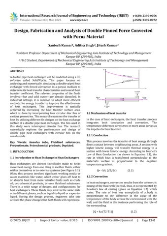
Key Words: Annulus tube, Fluidized substances, Proportionate, Petrochemical products, Depicted

1. INTRODUCTION

1.1 Introduction to Heat Exchange in Heat Exchangers

Heat exchangers are devices specifically made to helps move heat energy from one thingtoanother fluids, either withinthemselvesortoexternalsystems(seeFigure1.1). Often, this process involves significant working media or waste materials like water, which either gives off heat to or absorbs heat from more valuable fluids such as crude oil, petrochemical products, or even fluidized substances. There is a wide range of designs and configurations for heat exchangers. These fluids may exist in the same state orindifferentphases,suchasliquid-to-liquidorvapor-toliquid. During the design process, engineers take into accountthephasechangesthatbothfluidswillexperience.

1.2 Mechanism of heat transfer

In the case of heat exchangers, the heat transfer process integrates both conduction and convection. The temperaturedifferenceacrosstwoormoreareasservesas theimpetusforheattransfer.

1.2.1 Conduction

This process involves the transfer of heat energy through directcontactbetweenneighbouringareas.Asectionwith higher kinetic energy will transfer thermal energy to a section with lower kinetic energy. According to Fourier's Law of Heat Conduction (as shown in Equation 1.1), the rate at which heat is transferred perpendicular to the material's surface is proportional to the negative temperaturegradient.

Q=-kA.(dT/dx) (1.1)

1.2.2 Convection

Inheatexchangers,convectionresultsfromthevolumetric mixingofthefluidwiththewall,thus,itisrepresentedby Newton’s law of cooling (given as Equation 1.2) which states The rate of heat loss exemplarily of a body is proportionate to the difference in the value of the temperatureofthe bodyversus theenvironmentwiththe wall, and the fluid in this instance performing the role of thesurrounding.

[Q=ha(T2-T1)] (1.2)

International Research Journal of Engineering and Technology (IRJET) e-ISSN: 2395-0056

Volume: 12 Issue: 03 | Mar 2025 www.irjet.net p-ISSN: 2395-0072

ConvectionOverahotsurface

Theprocessofheattransfer fromthehotfluidtothecold fluidinaheatexchangerwithaconductivepartitiontakes placeinthefollowingstages:

1.Hotfluidtotheadjacentwallsurface,convection.

2.Throughthewallsurfaceside,conduction.

3. Convection transfers heat from the wall surface to the coldfluid.

1.3ConstructiveDesignofHeatExchangers.

1.3.1 Counter current Flow

In heat exchangers, both fluids are classified as hot and cold, positioned appropriately within the constructed systems. In these installations, operators differentiate between the fluid and the utility. The process fluid holds greatervalueasitcanbeseenasarawmaterial,aproduct, or sometimes even a by-product. The diagrams provided below depict how the process and utility fluids interact within the exchangers. Figure 1.3 illustrates that in counter current heat exchangers, the flow of the process fluid and the utility fluid travels in opposing directions. Thistypeofflowpatternisthemostcommonandefficient for heat exchangers. For fluids with significant temperature differences, this variation remains relatively constantacrossspecificsectionsoftheheatexchanger.

1.3.2 Co-existing or Concurrent Movement

AsdepictedinFigure1.4,inheatingexchangesystems,the processfluidandthemileagefluidpipelineflowinparallel or co-exist. This is likely the best scenario when the two imposed outlet temperature differences are similar to each order. Under most conditions, when the fluids are about to enter the heat exchanger, the temperature differencebetweenthe two fluidsisquitelarge. However, thisinputdifferencetendstoreducesignificantlyoverthe length of the heat exchangers which results into massive thermalstressandmaterialfailure.

2. LITERATURE REVIEW

2.1 Introduction

Automatic annulus tube double pipe heat exchanger was setuptohaveworkingoutertubelengthsupto1000mm. Hot water enters through a tube with an immersion rod while cold water is allowed to flow into the annulus througheitherendthus,theheatexchangercanoperateas a parallel flow exchanger. It has four circular disc fins of height200mmmanufacturedfromaluminum.

2.2 Development by Other Researchers

1. Theuseofheatexchangersinvariousindustrieshelps reduce costs and conserve energy. The double pipe heatexchangerhasbeenafocalpointinresearchdue to its versatility and effectiveness (Luki, 2008). To enhance the heat transfer rate and boost the performance of heat exchangers, different geometric configurationsofthesurfaceareaarebeingproposed

2. Researchershavealsoanalyzedtheimpactoftheheat exchanger'swall anditscontactsurfacearea withthe working fluids (JM and KR, 2016). This can be achieved by enlarging the contour surface area of the metal. It is believed that this will enhance the heat transfer rate; however, this improvement largely dependsontheshapeoftheadditionalsurfaceandthe prevailinghydrodynamicconditions.

Figure(1.2)
Figure1.3:countercurrentheatexchanger
Figure1.4:co-current-heat-exchanger

International Research Journal of Engineering and Technology (IRJET) e-ISSN: 2395-0056

Volume: 12 Issue: 03 | Mar 2025 www.irjet.net p-ISSN: 2395-0072

3. Naikel(1987)examinedconvectionheattransferfrom a horizontal rectangular base equipped with vertical rectangularfins.Thestudydemonstratedthattheheat transfer coefficient increased when the clearance between the shroud and the fin height was larger, as well as with a rise in fin height above the horizontal base.

4. Ji et al. (2005) investigated a cooling heat sink featuring triangular fins. Their results indicated that the effectiveness of the fin is influenced by the Reynoldsnumberandtheheightofthefin.

5. Zhang et al. (2012) conducted experimental research on heat transfer in a double pipe heat exchanger system incorporating helical fins and vortex generators. Their findings revealed improvements ranging from 87% to 115% for heat exchangers without fins compared to those using smooth tube heatexchangers.

6. Syed et al. (2015) explored the effects of longitudinal fins with varying tip thicknesses on the heat transfer rate in a finned double pipe heat exchanger. They discovered that these fins resulted in a significant increaseof170%intheheattransfercoefficient.

3. DESIGN AND FABRICATION

3.1 Material Selection

Inthedesignofaheatexchanger,thechoiceofmaterialsis the primary consideration. For double pipe heat exchangers, suitable materials include copper, stainless steel, and aluminum. The selection is influenced by the specific temperature and pressure requirements of the process,particularlywhenhandlingahotfluid.Aluminium is chosen for the inner tube and annulus due to its superior thermal conductivity. Additionally, the nickel braze used in aluminium exchangers possesses suitable melting and welding characteristics that allow it to be categorizedasanickel-basedalloy.

3.2 Basic Working Process of Double Piped Heat Exchanger

Adoublepipedheatexchangercanbegenerallydefinedas a device in which two liquids that do not mix, each at different temperatures, exchange heat with one another. Themetalliccontactbetweenthetwofluidsfacilitatesthis heattransfer,asdemonstratedinFigure3.1.

Figure3.1:Schematicdiagramofaparallelflow

HOTWATER (Fluid2)

Aluminum outer tubes(Dia=76mm)

Flowrate=0.42kg/s

Temperature Inlet = 48.1oC

COLDWATER (Fluid1)

Aluminum inner tube (Dia=51mm)

Flowrate=0.42kg/s

Temperature Inlet = 32.9oC

Table3.1:Tableoftheoreticalcalculation

3.3 Theoretical Calculations

Distinct temperatures can lead to individual characteristics for their respective fluid values, which can be retrieved from the Properties Table. Here, h denotes the convection heat transfer coefficient for both the inner andoutersurfacesofthetube,whileUsignifiestheoverall heat transfer coefficient. The hydraulic perimeter of an annular tube, determined through forced convection principles,istheresultofsubtractingtheperimeter ofthe inner tube from that of the outer tube. Consequently, average water velocity and the Reynolds number can be calculated.AReynoldsnumberexceeding10,000suggests turbulence in the flow, while a value below 10,000 indicateslaminarflow.

3.4 Modelling Work

The project entails the development of a 3D model for a double pipe heat exchanger. The specific fluids and materials that will be employed for both the heat exchanger shell and the body are considered to achieve the necessary maximum condensation heat transfer rate. The modelling task has been completed. To enhance heat transfer efficiency, the author is exploring designs that incorporate circular disc fins. The modelling is performed usingSolidWorks,a3Dmodellingprogram.Theinnertube isdesignedtoascaleofapproximately1100mminlength, while the outer tube measures 1000mm. To avoid complications from erroneous simulation components along the pipes, the author intends to keep the control volumeoftheheatexchangercompact.Themodelsforthe simulationworkcanbeviewedinFigure3.2.

International Research Journal of Engineering and Technology (IRJET) e-ISSN: 2395-0056

Volume: 12 Issue: 03 | Mar 2025 www.irjet.net p-ISSN: 2395-0072

3.5 Experimental setup

We constructed a double-pipe finned heat exchanger that is force convected with porous material. A smaller inner pipe is placed concentrically within a larger outer pipe workingasadoublepipefinnedheatexchanger.

• The inner pipe is a barrier for conduction, where a cold fluid enters through the inner pipe and the assisting fluid at a higher temperature passes around it in the annulus shapedregionwhichhasfins.

•Fourfinsintheshapeofcirculardiscsareemployedand thefinhasadiameterof200mm.

• The outer diameter of the inner tube and the inner diameter of the outer tube is 51mm and 76mm respectively. The inner pipe and outer pipe have lengths 1100mmand1000mmrespectively.

• The joining of the outer tube to the circular disc fins is donebybrazing.

Thedoublepipeheatexchangerwithconcentrictubeswas set up to conduct experiments. Hot water circulates throughpipesthathaveanimmersionrodlinkedtothem. Cold water can enter the annular space at either end to allow the heat exchanger to operate as a parallel flow

exchanger.Forbothpipes,thewatermassflowrateis0.42 kg/sec. First, to observe temperature effect on outer tube with four circular disc fins. Second, to observe temperature effect on middle height of four circular disc fins. Third, to observe temperature effect on full height of fourcirculardiscfins.

NameoftheMaterials SpecificationsDetails

Annualsmaterial Aluminum

Outerdiameter 76mm

Innerdiameter 51mm

TubeMaterial Aluminum

Length of the annulus tube 1100mm

Lengthoftheoutertube 1000mm

Thermal conductivity of aluminum 251W/mK

Table3.2:Tableformaterialandspecifications.

Toperformexperimentfordifferentparameterslikeeffect and variation of temperatures for the outer tubes, middle and full length on the fins, Temperatures of the outer tubeswithPorusmaterialandtablefanscanbemeasured usingdigitalthermometers

4. RESULT AND DISCUSSION

The values received for the heat transfer estimation of a simple double pipe heat exchanger is compared with experimentally obtained data so as to validate the numericalresults.ValidationisdoneforTemperature’sfor the outer tubes is measurable with thermocouples at hot waterinlettemperatureof48.1degreesCelsiuswithmass flowrateof0.42kilograms persecondandconstantmass flowrateof0.42intheouterandinnerpipes.Validationof rateofheattransferandheattransfercoefficientisdoneat the inlet hot temperature of 48.1 degrees Celsius for parallel flow direction with outer tube and outlet Temperature's for hot water is 42.9 degrees Celsius and 34.8degreesCelsiusforcoldwater.(SeeinTable4.1),(see infigure4.1

Temperature for the outer tubes can be measuredusingthermocouples.

Table4.1:Temperaturesfortheoutertubes

Figure3.2:Designinginsolidworks
Figure3.11Experimentalsetupofdoublepipeheat exchanger

International Research Journal of Engineering and Technology (IRJET) e-ISSN: 2395-0056

Volume: 12 Issue: 03 | Mar 2025 www.irjet.net p-ISSN: 2395-0072

4.1:Effectoftemperatureonoutertube

Temperatures for the middle fin height can be measuredusingthermocouple’s

Table4.2Temperatureforthemiddlefin tube.

Checking how fast heat moves and how much heatistransferred coefficient at inlet hot temperature of 48.0°C for parallel flow direction with outer tube and outlet temperature of hot water and cold water is 41.8°C and 33.7°C (see in Table 4.2) and (see in Figure 4.2).

Validation is completed for the Temperature’s for the entirefinheight,utilizingmeasuringthermocouplesatthe hot water inlet temperature of 48.0°C while changing the mass flow rate of 0.42 kg/s in the heat exchanger and maintaining a constant mass flow rate of 0.42 kg/s intheouterpipe. Validation is done for a cold water inlet temperatureof32.9°Cbyvaryingthemassflowrate,0.42 kg/s in the annulus side of the heat exchanger, keeping constant mass flow rate of 0.42 kg/s in the outer pipe. Validation of rate of heat transfer and heat transfer coefficient at inlet hot temperature of 48.0°C for parallel flow direction with outer tube and outlet temperature of hot water and cold water is 41.6°C and 33.5°C (see in Table4.3)and(seeinFigure4.3).

Figure4.2:Effectoftemperatureonmiddlefinheight.

Temperatures for the full fin height can be measuredusingthermo-couples.

T1 T2 T3 T4

416oC 415oC 413cC 401oC

Table4.3:Temperaturesforthefullfinheight.

Figure4.3:Effectoftemperatureonfullfinheight.

Temperatures for the outer tube with Porus materialfan.

Table4.4:TemperaturesfortheoutertubeswithPorus materialandtablefan

Figure4.4:EffectoftemperatureonoutertubewithPorus materialandtablefan

47.2°Cbyvaryingthemassflowrate,from0.42kg/sinthe heat exchanger, keeping constant mass flow rate of 0.42 kg/s in the inner pipe. Validation for a cold water inlet temperatureof33.5°Cbyvaryingthemassflowrate,0.42 kg/s in the annulus side of the heat exchanger, keeping constant mass flow rate of 0.42 kg/s in the outer pipe. Validation of rate of heat transfer and heat transfer coefficient at inlet hot temperature of 48.0°C for parallel flow direction with outer tube and outlet temperature of hot water and cold water is 40.5°C and 34.3°C (see in Table 4.4) and (see in Table 4.4). The difference in the temperature profiles for the heat exchangers can be seen. This shows that the addition of fins would also have positive improvements towards the heat transfer of both hotandcoldfluidsides.Thisisduetotheextendedsurface provided by the fins that helps in the heat transfer process. This extended surface provides a larger surface area and thus increase inheattransfer between those fluids.

Figure

International Research Journal of Engineering and Technology (IRJET) e-ISSN: 2395-0056

Volume: 12 Issue: 03 | Mar 2025 www.irjet.net p-ISSN: 2395-0072

5. CONCLUSION

After reading and obtaining information from a variety of sources,adouble-pipeheatexchangeristhesimplesttype of heat exchanger. However, the basic concepts of heat transfer must be well understood in order to design the required high-density two-pipe heat exchanger with liquid. Involves the design of the inner tube to be consideredwhicharethewingsattachedtotheouterwall of the outer tube to improve heat transfer. Some waterlike parameters are used as a constant parameter taking the liquid properties at 48.1 °C and 32.9°C respectively. The conclusions of this project may be abbreviated as follows:

1. The primary goal is to examine and study the fluid motion within the double pipe heat exchangers with respecttothefinnedoutertubedesign.

2. Prior to the implementation of the analysis, the entire model was created in a drop down 3D modeling applicationknownassolidworks.

3. This observation gives some knowledge of the enhancement made at the outer fins tubes in a parallel flowdoublepipeheatexchanger.

4.Thetemperatureprofilefortheoutlet’sinnerandouter fluids was measured for both types of 3D models: with a tubewithfinsandsimpletubewithoutatubewithfins.As it is known, in a double pipe heat exchanger, when the outer fluid is the hot fluid, the maximum outlet temperature(hot)oftheouterfluidis42.9°Cwhennofins areused,whileforthefinneddesignitis41.6°C

5. Some recommendations for improvements of the simulationistousemorevariousflow ratesforeachfluid in order to find better heat transfer profiles along the tubes. To conclude, in order to improve the heat transfer rates of the heat exchanger, there is various methods to enhanceitsuchasusingenhancedsurface,finingthetubes andPorusmaterialwithtablefantotheheatexchanger.

6. REFRENCES

Ameen, Sameer H. and Deyaa Mohammed N. Mahmood. “Experimental and Numerical Investigation for Structural and Thermal Characteristics of Externally Finned Double Piped Heat Exchanger.” Int. J. of Eng. Res. Tech, 3 (2014). Bhola, Mayank Kumar Singh, and Dr. Satyendra Singh. “Heat Transfer Enhancement in Concentric Tube Heat Exchanger in Ansys Fluent.” International Journal of Engineering Research Technology (IJERT) 4, (2015) https://doi.org/10.21275/ijertv41s040092. licensed under a Creative Commons Attribution 4.0 International License.

Dr. Y. Krishna. “CFD Analysis and Performance of Parallel and Counter Flow in Concentric Tube Heat Exchanger.” International Journal of Engineering TechnologyandResearch2no.11(2017):709-727.

Duan et al. “Numerical and Experimental Study on Using Internal Fins in a Double Tube Structure.” International Research Journal of Engineering and Technology,5no.4,(2018):4415-4419.

Hameed, Vinous M. “Experimental Study of Turbulent Flow Heat Transfer and Pressure Loss in a Double”. JournalofEnergyandEnvironment7(2015):149-158.

Hasan et al. “Study of Heat Transfer Enhancement in Double Pipe Heat Exchanger with Implemented Helical Wire.” Progress in Aeronautics Science and Technology1no.1(2017):1-12.

BIBLIOGRAPHIES

Santosh Kumar

AssistantProfessor AxisInstituteofTechnologyandManagement

KanpuraffiliatedfromAKTULucknow(UP) INDIA

Aditya Singh

U.GStudent

AxisInstituteofTechnologyandManagement

KanpuraffiliatedfromAKTULucknow(UP) INDIA

Jitesh Kumar U.GStudent

AxisInstituteofTechnologyandManagement

KanpuraffiliatedfromAKTULucknow(UP) INDIA

Turn static files into dynamic content formats.

Create a flipbook
Issuu converts static files into: digital portfolios, online yearbooks, online catalogs, digital photo albums and more. Sign up and create your flipbook.
Design, Fabrication and Analysis of Double Pinned Force Convected with Porus Material by IRJET Journal - Issuu