International Research Journal of Engineering and Technology (IRJET) e-ISSN: 2395-0056
Volume: 12 Issue: 03 | Mar 2025 www.irjet.net p-ISSN: 2395-0072


International Research Journal of Engineering and Technology (IRJET) e-ISSN: 2395-0056
Volume: 12 Issue: 03 | Mar 2025 www.irjet.net p-ISSN: 2395-0072
Murali S1 , Dr. Chethan K 2 , Dr. Achutha Herur Gopalaiah 3
1M. Tech (Structural Engineering) student, Dept of Civil Engineering, UVCE, Bengaluru, Karnataka, India
2 Associate Professor, Dept. of Civil Engineering, UVCE, Bengaluru, Karnataka, India
3 Sr. Manager PO/PMO, ESI Software India Pvt. Ltd., Bengaluru, Karnataka, India
Abstract - There are the challenges associated with welding, which includes development of residual stresses and distortions that can compromise structural stability and increase failure risks in the truss This study utilizes computational simulations to analyze the effects of welding parameters on the behavior of trusses. The simulations are conducted using Visual-Weld (CSM) with arc welding as the primary joining technique. The investigation focuses on the influence of welding-induced residual stresses, heat-affected zone (HAZ) characteristics, and geometric distortions on the overall performance of the Warren truss. Advanced finite element method tools are used to serve theabovepurpose. The study progressed with the design of the weld, bead and trajectory creation, material andweld inputcalibrations. Then the thermal, metallurgical and mechanical analysis is carried out. The weld effect on the load carrying capacity of warren truss is assessed in terms of determining the displacement due to effect of loading alone and displacement due to combined loading and welding. The result shows the significant effect of welding on the Warren truss’s load carrying capacity
Key Words: Heat-affected zone, Warren truss, Thermal analysis, residual stress, distortion, Mechanical analysis, Visual-Weld (CSM).
Trussesaremorepopularandveryoftenusedtypeofsteel structure. Truss consists of triangulated system of interconnected,straightstructuralelementsoftensionand compressionmembers.Membersoftrussesareactedupon with axial loads applied only at the joints. Trusses can be designedwithconnectionsofeithersimpleboltedorwelded connections for all types of member sections. Trusses are widely used in bridges, buildings, towers, and industrial frameworks due to their high strength-to-weight ratio. Trussesareclassifiedbasedongeometry,loadconditions, loaddistribution,andmaterialcomposition.WarrenTruss comprises of equilateral triangles, ensuring even load distribution.Weldingprovidescompletefreedomofdesign tostructuralengineersaswellasarchitects.Properlywelded jointsarestrongerthanboltedjoint. Someofthecommon weld defects include lack of fusion, porosity, cracking, distortionsandundercut.Thedifferentweldparametersare considered.
Travelspeedisthespeedatwhichtheelectrodemoves alongtheweldjoint.ItisalsoknownastheWeldVelocity.It isusuallyrepresentedasthemm/min.Optimumweldspeed providesuniformpenetrationandcontrolledbeadsize.Heat input affects weld microstructure, Heat affected zone and mechanical properties. Heat input is the amount of heat energydeliveredtothematerialduringwelding.Optimum heat input creates balancedmicrostructure andcontrolled stress. Weld penetration refers to the depth to which the weldmetal(fillermaterial)andbasemetal(workpiece)fuse togetherduringtheweldingprocess.Toensuretheproper bonding between the materials,and to expect materialsto handlemechanicalloadsandstresses,itisimportanttohave the proper specified and complete penetration. Welding currentdeterminestheheatinputtotheweldjoint,affecting penetration and deposition rate. Optimum weld current provides proper penetration, bead profileand good fusion with base metal. Arc voltage is the potential difference betweentheelectrodeandtheworkpiece,measuredinvolts (V). Optimumarc voltage provides stablearc, proper bead widthandreduceddefects.
Visual-Weld is a Computer-Aided Engineering (CAE) softwarespecificallydesignedforweldedstructureanalysis. It is a module of Visual-Environment, developed by ESI Group, and is commonly used for weld simulations in structural and manufacturing industries. It integrates advancedfiniteelementanalysis(FEA)withweldingprocess simulations, helps to study thermal, mechanical and metallurgicaleffectsofwelding. Visual-Weld(CSM)provides awiderangeoffeaturesforweldingprocesssimulationand analysis. The primary capability of the software includes WeldmodellingandSimulation,Heatsourcemodellingand Thermal Analysis (Temperature distribution, Cooling rate, andHeat-affectedzones(HAZ).Structuralandresidualstress analysis can be carried out using the Visual-Weld (CSM) software. The software also providesthe provision for the Material and Metallurgical analysis and phase Transformationmodellingbyincorporatingtheweldmetal properties. BenefitsofUsingVisual-Weld(CSM)isaccurate weldingsimulation,reducesphysicaltestingcosts,predicts residualstresses,preventsweldfailures,optimizeswelding

International Research Journal of Engineering and Technology (IRJET) e-ISSN: 2395-0056
Volume: 12 Issue: 03 | Mar 2025 www.irjet.net p-ISSN: 2395-0072
parameters, improves productivity, reduces distortion, minimizespost-weldcorrections.
Finite element analysis is a powerful computational technique used to solve complex engineering problems involvingstructures,heattransfer,fluiddynamics,andmany more. By breaking down a larger system into smaller, simplerparts(finiteelements),FEAenablesustoanalysethe behaviour of materials and components under various conditions,suchasload,temperature,orpressure.Thesteps to be followed in FE analysis is discretization, meshing, developinggoverningequations,elementformulation,input boundarycondition,obtainsolutionandpost-processing
Manik, et al. (2012) investigatedtoknowthemechanical propertiesofthecastironandmildsteelbeforeandafterthe welding. The metals with any cross sections that have undergone the Heat treatment shown the result that the stress will be reduced after welding compared to that without the heat treatment. Also, result is evidential that hardnessafterweldingisincreasedifcarriedouttherapid cooling. The experimentations carried out by the Authors suggested that the proportional limit of the workpiece is reducedduetotheweldingeffect,strengthalsoreduced,but thehardnesswasincreased.Henceauthorsconcludesthat there is significant change in the properties of the metals becauseofweldingimposedonit.
Van Nhat Nguyen, et al. (2016) carriedoutComputational simulationweldingwiththehelpofFiniteelementMethod andpredictedtheresidualstressesandstrains.Theycarried out Thermal, Metallurgical and Mechanical Analysis post welding. Authors used Visual-Weld software for the simulation and Analysis of T-Joint and the results of Deformation, Hardness, phase transformation were tabulated. Authors indicated that Heat energy affects penetration depth of seam weld. Authors suggests using properweldmaterials,tohavegoodweldgapandtomake thepropersurfacecleanbeforeproceedingwiththeprocess ofwelding.
Tadano Satoshi, et al. (2019) investigatedonthesteelangle sections of the trusses and the deformation that the angle sectiontakesplaceduetotheweldingprocesses.TheAuthors analysedandevaluatedweldingdeformationusingbothJoint model aswell asthereal-scaleTrussstructuremodel.The Authors provides the result after the study that the main beamofweldedtrussstructurewasseentobearchedagainst the direction of angular distortions. They used uniformly distributedInherentstrain theory withintheMechanically meltingzones.TheAuthorsalsostudiedthetheoreticalways in which the welding deformation in the Truss structure couldbereduced
Okonkwo V O, et al. (2021) investigated on the different trussesanddeterminedtheeffectofsecondarystresseson thefinalweightofthestructure.Theymadethecomparison between the pin-jointed and rigid jointed trusses. Authors afterthestudyareintheFavouroftheRigid-Jointedtrusses andsuggeststhattheRigidlyjointed(welded)trussesrequire lighter and cheaper structures than pin-jointed trusses. Welded Joints when made comparison with the pin joints, former’sloadcarryingcapacityissubstantiallyincreasedin comparisonwiththelater.
Mohamed M. Ali and Moatasem M. Kh (2020) investigated on the effect of the welding parameters on the mechanic propertiesofthesteelweldment.Toknowtheeffectcaused bydifferentweldingparameters,thefollowingparameters wereconsidered:Weldingspeed,Platethickness,Typeofarc welding,Typeofelectrodeandweldingcurrent.Theresultof thestudysuggestedthatastheheatinputincreases,theweld speedreduces,buttheweldcurrentincreases,andthereby,it iseffectiveforlargeplatethickness.TheAuthorsobserved changeinthephaseattheHeataffectedzoneroot.Theyare intheopinionthatweldelectrodealsohastheinfluenceon the efficiency of the welding process. The Authors also suggeststheweldinginputforbetterweldresults.
Dengyiding Jin, et al. (2021)investigatedontheeffectofthe weldingonthestiffnessandstrengthoftheCFST(Concretefilled steel tubular) K and Y-Joint. The Authors used the Advanced FEM tools for the achievement of the above purpose.Thetestdatawerecollectedbytheauthorsandare used for validation. To facilitate thesimulation of Welding heatgeneration,as well asthe Residual stress soobtained due to welding. The study carried out by the authors suggested that Brace to Chord ratio is the important governingfactorintheJointfailure.Authorshintedtheresult thatwhentheweldlegthickness isreduced,itmoderately reducesthejointstrengthandstiffness,butindeedsmaller andlowerregionofresidualstressisinduced.
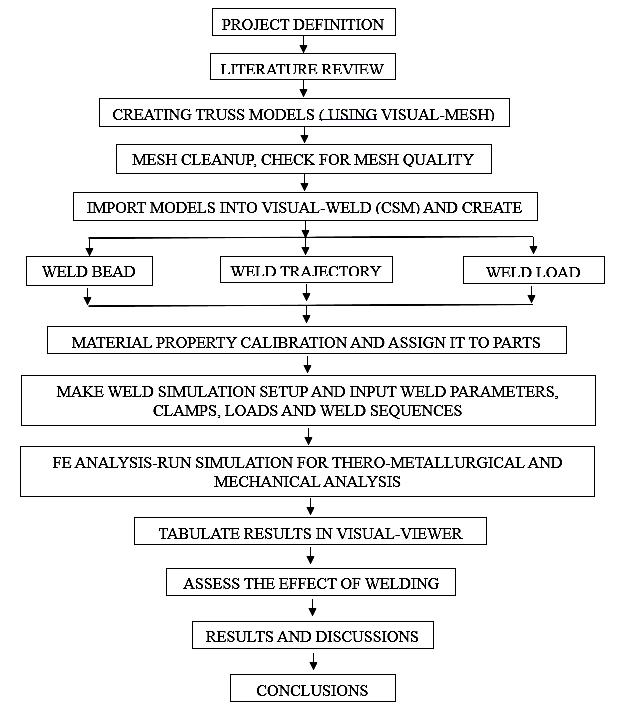
TheMethodologyfollowedinthestudyareasfollows:
(i) Defining the project and its objectives, identify the key factors affecting the load-carrying capacity of welded trusses, such as welding parameters, heat-affected zones (HAZ)andresidualstresses
(ii) Prepare the Truss model required to carry out simulationsusingtheVisual-MeshSoftware.Meshthemodel, cleanupandcarryoutsuitablechecksonmeshquality
(iii) Create weld trajectory, weld load, material property calibration,andassignmaterialtoparts.
(iv) Making Weld simulation setup by inputting Weld parameters, initial ambient temperature, Clamping conditions,Loadandweldsequence.

International Research Journal of Engineering and Technology (IRJET) e-ISSN: 2395-0056
Volume: 12 Issue: 03 | Mar 2025 www.irjet.net p-ISSN: 2395-0072
(v) Run the simulation to get the Normal Termination of bothThermo-MetallurgicalandMechanicalAnalysis.
(vi)EvaluatetheResidualstressesanddeformationsresults.
(vii)AssesstheeffectofweldingofdifferenttypesofTrusses byexaminingtheiterationswithandwithoutloadingit.
(viii)Tabulationoftheresultsobtained.
(ix)Makediscussionsovertheresultsobtainedandgiving theconclusionsoftheworkcarriedout
Theflowchartofthe methodologyfollowedinthe work is representedintheFig-1.

Fig -1:Flowchartofthemethodology
4. WORK DONE
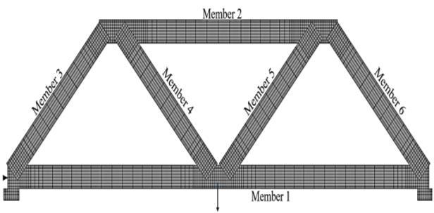
TheCADdrawingoftheTrussispreparedintheVisual-Mesh software by properly taking into consideration the dimensions.Eachmemberisstoredastheparts,noweach partismeshedintheVisual-Meshsoftware.
Onceafterthemodelismeshed,thenitiscarriedoutwith suitablechecksformeshquality TheArcweldingisusedto connect the members of the Trusses at joints. The weld designisdone,andsuitablechecksarecarriedout.

Fig -2:Warrentrussmodeledinthesoftwareand consideredforthestudy
TheMaterialpropertiesofthesteelusedintheFEanalysis aretabulatedasbelowinTable-1.Thesepropertieslisted are at the ambient temperature, before the start of the weldingprocess
Table -1: Materialproperties
Material Property Value Units
Modulusofelasticity 2.1x10⁸ kN/m2 Poisson’sratio 0.3Density 78.2 kN/m3
ThedetailsoftheWarrentrussmodelarelistedoutinthe Table-2
Table -2: DetailsofTrussModel
SectionaldesignationofTruss members ISA80X80
SizeofTrussmembers 80mmX80mm
ThicknessofTrussmember 8mm
SectionalareaofTrussmembers 1221mm2
WeightpermeterofTrussmembers 9.6kg
Welddimension 5mmX5mm
Basedimension 120mmX80mmX 40mm
The details of the weld parameters provided and the minimum required value to be provided are given in the Table-3
Table -3: Designoftheweld

International Research Journal of Engineering and Technology (IRJET) e-ISSN: 2395-0056
Volume: 12 Issue: 03 | Mar 2025 www.irjet.net p-ISSN: 2395-0072
Once the design of the weld and providing the weld parametersaredone,thechecksforwhethergivenwelded joint is sufficient to safely carry the applied load or not is done.Theweldstrengthwasfoundtobesufficientandjoint strengthalsofoundtobesufficienttocarrytheloadapplied onthetruss.
AspertheIS800andAWSD1.1codalprovisions,thedesign of the weld is carried out For the given weld, angular distortioninducedisestimated.
ForWarrentruss:
ProvidedEnergyinputisq=600J/mm
Angulardistortioninfilletweld, Wheretistheplatethickness


0.0017857radians

Hence,Angulardistortioninfilletweldis 0.10230

According to AWS D1.1:2000 the allowable angular distortionforstructuralwelding≤10andallowableangular distortionforprecisestructureswithtighttolerance≤0.50
Asangulardistortionislessthantheselimits,itissafe.
Asperthedesignoftheweld,theminimumrequiredweld thicknessandminimumlengthoftheweldisprovided,toget properweldment.
Weldbeadandweldtrajectoriesarecreated.Weldtrajectory denotes the path in which the welding is proceeded The poisson’s ratio is unaffected with the increase in the temperatureandthevalueofPoisson’sratioforthesteelis taken as 0.3, independent of temperature. The Young’s Modulusanddensityvarieswiththetemperature Thenthe materialcalibrationisdone.
ThecalibrationofWeldinputsuchaspenetration,lengthof Arcweld,widthofArcweldetc.aredone,forthepurposeof achievingthegoodqualityweld.Forthispurpose,ajointof themodelisconsidered,weldinginputsarealtereduntilthe normal termination of the Thermo-Metallurgical and Mechanicalprocesstakesplace.AfterNormaltermination, crosscheckforsufficientheatinputpenetrationisdone.
Clampingiscreated.Clampingholdstheworkpiecesinthe correct position while the welding takes place. Clamping provides the accurate alignment of workpieces, improves weld quality, distortion and warping will be prevented, safetyandstabilityisincreased.Clampsmustbeprovidedat theplaceswheretherewouldbemoredistortionsduringthe
processofwelding.Thepropersequenceisfollowedduring theprovidingofclampingaswellasduringtheremovalof theclamping.
Thermalandmechanicalcontactsaredefined.
The simulation setup is done. The simulation details are presentedintheTable-4
Table -4: Simulationdetails
The simulation setup includes project description and materialassignment,processchaining,definitionofwelds, clampingsystem,heatexchangecondition,loadingcondition, contactandconnectionconditionandsequencemanager
Afterthesimulationsetupisready,mechanicaldisplacement analysisandmechanicalvon-misesresidualstressanalysisis carriedout.
Mechanical displacement analysis is the study of the deformationormovementofthe welded materialsduring and after the welding process. This analysis is crucial for understanding how the application of heat, the fusion of materials,andthecoolingratesaffectthegeometry.
Thermalexpansionandcontractionplayanimportantrolein mechanical displacements during welding. When the material is heated in the welding process, it expands, and when it cools, it contracts. The heat-affected zone (HAZ), weld bead, and base material all experience different temperatures and cooling rates, leading to differential expansionandcontraction
Coolingrateisfasterintheweldmetalcomparedtothebase metal,thisthermalmismatchcancreateresidualstressesin different regions,especiallyintheregionsofheat-affected zone(HAZ).

International Research Journal of Engineering and Technology (IRJET) e-ISSN: 2395-0056
Volume: 12 Issue: 03 | Mar 2025 www.irjet.net p-ISSN: 2395-0072
ToassesstheeffectofweldingontheLoadcarryingcapacity ofdifferentmembersofthetruss,thedisplacements(both vertical and lateral displacements) are measured at the differentnodesofthewarrentruss. Itisbecausetheforce anddisplacementsaredirectlyrelatedtoeachother.
The truss members are measured for the displacement beforeloadingwhichindicatesthedisplacementinducedin themembersbecauseofwelding.Also,thetrussmembers are measured for displacements at different nodes after loading which indicates the displacement induced in the membersduetothecombinedeffectofWeldingandloading. Hence this analysis provides the effect that welding is inducingonthedifferentmembersoftheWarrenTruss.
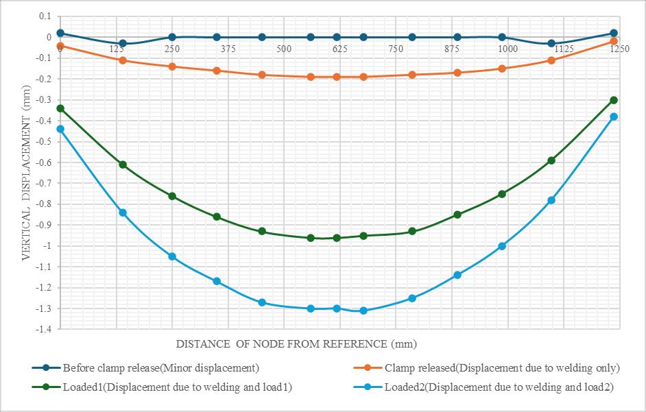
The curves to show the effect of welding are plotted. The curveof‘Beforeclamprelease’indicatesthedisplacements inthemembersduetothelocalizedresidualstressespresent afterwelding.Itistheminordisplacementspresentinthe members.
Thecurveof‘Clampreleased’indicatesthedisplacementsat the different nodes in the member purely because of welding.
The curve of ‘Loaded’ indicates the displacements at the differentnodesinthememberduetothecombinedeffectof weldingandloading.
Forthe Warrentruss,the resultsshowsthatthereis both positive and negative effect of welding in the different membersofthewarrentruss.
Boththeverticaldisplacementandthelateraldisplacement due to the loading and welding are plotted for both horizontalanddiagonalmembers.


International Research Journal of Engineering and Technology (IRJET) e-ISSN: 2395-0056
Volume: 12 Issue: 03 | Mar 2025 www.irjet.net p-ISSN: 2395-0072

-5:Verticaldisplacementindiagonalmember meetingatthesupport(member3)

Chart -6:Lateraldisplacementindiagonalmember meetingatthesupport(member3)

Chart -7:Verticaldisplacementindiagonalmember meetingatthecenter(member4)

Chart -8:Lateraldisplacementindiagonalmember meetingatthecenter(member4)
The charts 1-8 are obtained after performing the simulations to assess the effect of welding on the Warren truss.Theresultsclearlyshowsthattheeffectofweldingis differentforthedifferentmembersofthetruss.Hencethe charts for the vertical and lateral displacements in each memberoftheWarrentrussarepreparedseparatelyandis analyzedtoassesstheeffectofweldingoneachmember.
Basedontheresultsobtained,thefollowingdiscussions ontheresultsarepresentedasfollows:
(i)IncaseofHorizontalbasemember,Weldingincreases the vertical displacement at the center but reduces the vertical displacementaway fromthecenter. Atcenterfor load case 1 maximum of 1.94% increase in vertical displacement and for load case 2 maximum of 1.29% increaseinverticaldisplacementisnoticed.
(ii) In case of Horizontal base member, the lateral displacementinducedduetogivenloadingisincreaseddue to welding. Due to welding, for load case 1 maximum of 77.27%increaseinlateraldisplacementisnoticed.Forload case2maximumof42.5%increaseinlateraldisplacementis noticed.
(iii) In case of Horizontal top member, the vertical displacementinducedduetogivenloadingisincreaseddue to welding. Due to welding, for load case 1 maximum of 19.79%increaseinverticaldisplacementisnoticed.Forload case2maximumof14.62%increaseinverticaldisplacement isnoticed.
(iv) In case of Horizontal top member, the lateral displacementinducedduetogivenloadingisreduceddueto welding.Duetowelding,forloadcase1maximumof18.11% decreaseinlateraldisplacementisnoticed.Forloadcase2 maximum of 12.31% decrease in lateral displacement is noticed.

International Research Journal of Engineering and Technology (IRJET) e-ISSN: 2395-0056
Volume: 12 Issue: 03 | Mar 2025 www.irjet.net p-ISSN: 2395-0072
(v) IncaseofDiagonal membermeetingatthesupport, the vertical displacement induced due to given loading is increased due to welding. Due to welding, for load case 1 maximum of 37.5% increase in vertical displacement is noticed. For load case 2 maximum of 32.14% increase in verticaldisplacementisnoticed.
(vi)IncaseofDiagonalmembermeetingatthesupport, the lateral displacement induced due to given loading is reduced due to welding. Due to welding, for load case 1 maximum of 9.42% decrease in lateral displacement is noticed.Forloadcase2maximumof6.57%decreaseinthe lateraldisplacementisnoticed.
(vii)IncaseofDiagonalmembermeetingatthecenter,the verticaldisplacementinducedduetogivenloadingisslightly reduced due to welding. Due to welding, for load case 1 maximum of 5.88% decrease in vertical displacement is noticed. For load case 2 maximum of 3.6% decrease in verticaldisplacementisnoticed.
(viii)IncaseofDiagonalmembermeetingatthecenter, the lateral displacement induced due to given loading is reduced due to welding. Due to welding, for load case 1 maximum of 9.39% decrease in lateral displacement is noticed.Forloadcase2maximumof6.5%decreaseinlateral displacementisnoticed.
Thestudycarriedouttoassesstheeffectofweldingonthe loadcarryingcapacityofthewarrentruss Theweldinput calibration and material calibrations are done Thermal, metallurgical and mechanical analysis are carried out and basedontheresultsobtained,thefollowingconclusionsare drawn:
(i) The effect of welding is noticed to influence the load carrying capacity of truss. The way it influences and the proportionitinfluencesdependsonthetypeofmemberand thetypeoftrussandweldinputparameters.
(ii)Theclamp releasepoint oftimeisfound critical,since peak residual stresses and distortions are found due to weldingsoonafterthereleaseoftheclamp.Hencetheclamp release time must be properly designed to reduce the distortionsandresidualstressesinthemembersoftruss.
(iii) Outer diagonal members near supports of truss have higherpercentageincreaseinverticaldisplacement,making themhighlysensitivetoweldingeffects,alsomakingthema weakpointunderweldedconditions.
(iv)Basehorizontalmembersandouterdiagonalmembers near the supports are the critical members because of welding.
(v) Load redistribution in Warren trusses appears more efficient,reducingwelding-inducedstresseffectsincertain
members.Andlikelyduetoimprovedlateralstiffnessfrom weldedjoints,weldingreducesthelateraldisplacementsin diagonalmembersandtophorizontalmembers.
Thestudycanbeextendedwiththeobservationofthelongterm behavior of the welded trusses subjected to cyclic loading and can assess fatigue durability and fatigue performance. The study about investigation of post weld heattreatmenttechniquestomitigateresidualstressesand toenhanceweldqualitycanbecarriedout
8.
TheauthorsexpressgratitudetoESISoftwareIndiaPvt.Ltd. forgrantingaccesstotheirsoftware,whichwasimmensely beneficialinthesuccessfulcompletionofthework
[1] Manik, Halder P K, Paul N and Shamimur Rahman, “Effectofweldingonthepropertiesofmildsteel&castiron specimen”, ‘International Conference on mechanical,industrialandenergyengineering’,2012.
[2] VanNhatNguyen,Quoc-ManhNguyenandShyh-Chour Huang, “Study Computational Simulation and ExperimentalofTee-JointbyVisual-WeldSoftwareand Tungsten Inert Gas Welding Process”, ‘IEEE International Conference on Advanced Materials for ScienceandEngineering’-IEEE-ICAMSE2016
[3] Tadano Satoshi, Mizuuchi Rieko, Sugiura Kouji and NakataniYujiro,“Experimentalandnumericalstudyof weldingdeformationintrussstructureofsteelangles”, 2019/page52-58
[4] Okonkwo V. O., Onodagu P. D. and Udemba J. N, “An InvestigationontheEffectsofRigidJointsontheWeight and Load Carrying Capacity of Steel Trusses”, ‘IOSR Journal of Engineering (IOSRJEN)’, Vol. 11, Issue 3, March2021/page33-39.
[5] Mohamed M. Ali and Moatasem M. Kh, “Effects of Welding Parameters on Characterization and MechanicalPropertiesofSteel37Weldments”,‘Journal ofEngineeringSciences’,Vol.48,No.2,March2020,PP. 212–221.
[6] Dengyiding Jin, ChaoHou and Luming Shen, “Effect of welding residual stress on the performance of CFST tubular joints”, ‘Journal of Constructional Steel Research’,Elsevier-2021.

International Research Journal of Engineering and Technology (IRJET) e-ISSN: 2395-0056
Volume: 12 Issue: 03 | Mar 2025 www.irjet.net p-ISSN: 2395-0072


Mr. Murali S, M.Tech student (Structural Engineering), UVCE Bangalore. Completed B.E in Civil EngineeringfromBIT,Bangalore.
Dr. Chethan K, Associate Professor, Department of Civil Engineering, UVCE, Bangalore. Has completed M.Tech (Industrial Structures-NITK) andPhD(NITK).
Dr. Achutha Herur Gopalaiah, Sr. ManagerPO/PMO,ESISoftwareIndia Pvt. Ltd. Bengaluru. Has completed M.E (Structural Mechanics, MSRIT) andPhD(UVCE).