
International Research Journal of Engineering and Technology (IRJET) e-ISSN: 2395-0056
Volume: 12 Issue: 03 | Mar 2025 www.irjet.net p-ISSN: 2395-0072


International Research Journal of Engineering and Technology (IRJET) e-ISSN: 2395-0056
Volume: 12 Issue: 03 | Mar 2025 www.irjet.net p-ISSN: 2395-0072
Er. Anil1 , Dr. Aarti loi2
1Assistant Professor Department of Electrical Engineering, Sant Baba Bhag Singh University, Khiala Distt.: Jalandhar
2Assistant Professor Department of Physiotherapy, Sant Baba Bhag Singh University, Khiala Distt.: Jalandhar ***
Abstract - Theincreasingdemandforelectrotherapydevices calls for sustainable and eco-friendly solutions to reduce environmentalimpact.Traditionalelectrotherapysystemsrely heavilyon disposablecomponents and non-renewableenergy sources, contributing to environmental waste. This paper explores the integration of solar power in electrotherapy devices, focusingonthedesignofa solar-poweredsystemthat steps up DC signals using MOSFET technology and photovoltaic(PV)cells. Thedevelopedmodelsuccessfullysteps up the voltage, providing a sustainable, portable, and ecofriendly alternative for electrotherapy treatments. The use of solar energy not only minimizes resource consumption but alsoenhances deviceportability,makingitsuitableforoff-grid and remote locations. The paper highlights the potential of renewable energy technologies to reduce the ecological footprint of electrotherapy devices while ensuring effective and safe treatment. By combining electrical engineering with electrotherapy, this research paves the way for future innovations in sustainable healthcare solutions.
Key Words: Electrotherapy,SolarEnergy,BoostConverter, MOSFET
Asthedemandforsustainableandportableelectrotherapy devicescontinuestoincrease,solar-poweredsolutionsoffer an excellent opportunity to reduce reliance on nonrenewable energy sources while ensuring effective treatment.Theabilitytopowerelectrotherapydevicesusing solarenergynotonlyaddressesenvironmentalconcernsbut alsoenablestreatmentinremoteoroff-gridlocationswhere conventionalelectricalgridsareunavailable[1].However,to ensure that the energy generated by solar panels is efficiently converted into a usable electrical signal for electrotherapy, power conversion technologies must be employed. Specifically, this paper focuses on the use of Metal-Oxide-Semiconductor Field-Effect Transistor (MOSFET) technology to step up the low-voltage direct current (DC) signals produced by solar panels to the appropriate voltage levels needed for electrotherapy applications[2].
MOSFETsarewidelyrecognizedfortheirhighefficiency,fast switching capabilities, and reliable performance in power
conversioncircuits,makingthemidealforuseinsteppingup low-voltage DC signals. In this paper, the MOSFET technologyisutilizedtoincreasethevoltagefromthesolar paneltothenecessarylevelforelectrotherapytreatments. The use of MOSFETs ensures stable, efficient voltage conversionwithminimalenergyloss,allowingforoptimal power delivery to electrotherapy devices. This step-up converterdesign,drivenbyMOSFETtechnology,iscritical for ensuring that the electrotherapy devices receive the correctvoltageforvarioustypesoftreatment[3].
Furthermore,thispaperalsoexplorestheconversionofthe stepped-upDCsignalintobothalternatingcurrent(AC)and DC outputs for testing purposes. AC output is typically requiredfortreatmentslikeTranscutaneousElectricalNerve Stimulation(TENS)orInterferentialCurrentTherapy(IFC), whileDCoutputismorecommonlyusedintreatmentssuch asNeuromuscularElectricalStimulation(NMES).Theability toproducebothACandDCoutputsfromthestepped-upDC signalmakesthissystemversatileandadaptabletoawide range of electrotherapy techniques, offering flexibility in treatmentapproachesfordifferentpatientneeds[3].
To model and simulate this power conversion process, MATLAB 2021a is used as the simulation tool. MATLAB providesanadvancedsimulationenvironmentthatallows for detailed modeling and testing of power electronics circuits. By utilizing MATLAB, the design of the step-up converterthatusesMOSFETtechnologytoincreasethelowvoltageDCsignaliscarefullyanalyzed.Thesimulationalso facilitatestheconversionoftheDCvoltageintobothACand DC outputs for electrotherapy applications, enabling the evaluation of the system’s performance under various conditions[4-7].
Thesimulationprocessbeginswiththemodelingofthesolar panel’slow-voltageDCsignal.Thissignalisthenfedintothe step-up converter, where the MOSFET-based technology increases the voltage to the desired level. The simulation includesbothACandDCoutputtesting,whereparameters suchasfrequency,waveform,andvoltageareadjustedfor compatibility with different electrotherapy modalities. ThroughMATLABsimulations,variousconditions suchas changes in solar intensity, variations in load, and voltage regulation canbetestedandoptimizedforbettersystem efficiencyandperformance[8-10].

International Research Journal of Engineering and Technology (IRJET) e-ISSN: 2395-0056
Volume: 12 Issue: 03 | Mar 2025 www.irjet.net p-ISSN: 2395-0072
By utilizing MATLAB simulations, it becomes possible to thoroughlytestandevaluatetheperformanceofthesystem beforebuildingaphysicalprototype.Thesimulationresults provide valuable data regarding the efficiency, voltage stability,powerlosses,andoveralleffectivenessofthepower conversion system. These insights will serve as the foundationforthedevelopmentofapractical,solar-powered electrotherapy device capable of providing reliable and efficienttherapeutictreatments.
The objective of this research is to design and develop a solar-powered electrotherapy system that leverages MOSFET technology for efficient power conversion. This approach not only offers a sustainable and eco-friendly solutionforelectrotherapybutalsoincreasestheversatility and accessibility of treatments. With this system, patients canbenefitfromreliable,off-gridelectrotherapy,makingit especially valuable in regions with limited access to traditional power sources. By combining MOSFET-based power electronics and MATLAB simulations, this paper presentsapracticalandinnovativesolutionforthefutureof sustainable,solar-poweredelectrotherapydevices[11-13].
TheoperationofaPVcellissimilartothatofadiodewitha junction, whereby absorbed light energy produces charge carriersseparatedatthejunction.InanidealPVcell,thereis no series loss or leakage to ground, but in real PV cells, resistancesareintroducedinequivalentcircuitstoaccount forthesenon-idealities.Figure1.1illustratestheequivalent electricalcircuitforthecompositephysicsofPVcells,which is the basis for the proposed PV model's developmental model.Aconstantcurrentsource,Iph,representsthecurrent produced by photons, while the shunt resistance, Rsh, accountsforshunt-leakagecurrent,Ish.Theseriesresistance, Rs,representsthevoltagedropattheoutput.Smallchanges inRssignificantlyaffecttheoutputofthePVmodule,andPV power conversion efficiency (PPCE) is sensitive to such changes,butnottochangesinRsh.Thecurrentandvoltageof thePVpaneldependontheloadvalueandexhibitnonlinear, power-limitedelectricalcharacteristics.EquivalentElectrical circuitmodel of PVcells.TheEquation(1)definingoutput currentofthenon-idealPVcellwasderivedusingKirchhoff’s currentlawasfollows:Icell=Iph−Id−Ish(1)
Equation(2)formulatesthetotalcurrentthataPVcellcan provide, taking into account active radiation (G) and referenceradiation(Gr),aswellasthemoduletemperature (Tc) and reference temperature (Tcr) of the component. Electrical specifications for PV modules are typically providedbymanufacturersatstandardconditions,withsolar radiation at 1000 W/m2 and a cell temperature of 25 oC, whichcorrespondtothevaluesofGrandTcr,respectively. Icell=Ir+[a(G/Gr)(Tc−Tcr)+(GGr−1)Isc](2)Equation(3) and(4)areusedtoformulatethevoltageofaPVcell,where the temperature coefficient of open circuit voltage is representedbyß.Theshortcircuitcurrentofthemoduleis
characterized by the parameter Isc and α represents the temperature coefficient of short circuit current. Vcell = (−β)(Tc−Tcr)−Rs∆I+Vr∆I=[a(GGr)(Tc−Tcr)+(GGr−1)Isc] (3)(4)Inthiscontext,Rsisthe:parameterusedtoindicate thevoltagedropatthePVcell'soutput.Thereferencevalues forcurrentandvoltagearedenotedbyIrandVr,respectively, which are obtained from the I-V curve. To design a PV module, individual PV cells are connected in series and parallel. This configuration gives the output current and voltage of the PV module as shown in Equation (5) and Equation(6),respectively.Vm=NscVcellIm=NpcIcell(5) (6)Inthiscontext,Vmrepresentstheoutputvoltage,while Im represents the output current. Nsc and Npc denote the number of PV cells connected in series and parallel, respectively. The suggested PV module can be used in transientanalysisofpowersystemsthathavePVpanels.Itis alsohelpfulfortestingMaximumPowerPoint(MPP)tracking methods.Currently,integratingsolarenergyintomicrogrids isatoppriorityfor
the power systems industry. Modelling renewable energy sourcesforlarge-scalepowersystemintegrationsimulations isnowmorecriticalthanever,asthesesimulationtoolswill be a crucial part of the optimal design and intelligent managementprocesses.
The cells convert solar energy into power very efficiently. Theyaremadeofvarioussemiconductormaterials.Thereare two types: positive rate and negative rate. This modular techniqueisusedtofabricatesolarcellswithhighconversion efficiencyandlowcost.Whena solarcellcollectsphotons, siliconatomsareexcited.Agridofmetalconductorscaptures thefreedelectronsandpullsthemaway,causinganelectric current to flow. A photovoltaic (PV) module is the main component of a PV system, consisting of solar cell circuits sealedinanenvironmentallyfriendlylaminate.Tomeetthe energydemand,multiplePVmodulesareoftenconnectedin seriesandparallel.ThespecificationsofthePVmoduleused inthecircuitareasfollows:

International Research Journal of Engineering and Technology (IRJET) e-ISSN: 2395-0056
Volume: 12 Issue: 03 | Mar 2025 www.irjet.net p-ISSN: 2395-0072
The metal oxide semiconductor field effect transistor (MOSFET)isasemiconductordevicethatcanbecontrolled byagatesignal(g>0).TheMOSFETdeviceisconnectedin parallel with an internal diode that turns on when the MOSFETdeviceisreversebiased(Vds<0g=0).>0org=0), thediodeisconnectedinparallel.
AMOSFETdeviceturnsonwhenapositivesignalisapplied to the gate input (g > 0) regardless of whether the drainsourcevoltageispositiveornegative.Withnosignalatthe gateinput(g=0),onlytheinternaldiodeconductswhenthe voltageexceedstheforwardvoltageVf.

Figure2.1:Current-voltageandpower-voltage characteristicsofthePVarraymodel
Whenapositiveornegativecurrentflowsthroughthedevice, theMOSFETturnsoffwhenthegateinputgoesto0.Ifthe currentIisnegativeandflowsthroughtheinternaldiode(no gatesignalorg=0),theswitchisturnedoffwhenthecurrent Ireaches0.
TheforwardvoltageVdsvaries:
Vds=Ron×I
Whenapositivesignalispresentatthegateinput.
Vds=Rd×I-Vf+Lon×dI/dt
Whentheanti-paralleldiodeconducts(nogatesignal).Ron Diode Inductance is only available in continuous models. MostapplicationsshouldsetLontozeroforbothcontinuous anddiscretemodels.TheMOSFETblockalsoincludesaseries Rs-Cssnubbercircuitthatcanbeconnectedinparallelwith theMOSFET(betweennodesdands).
In this section, we present a simulation evaluation of the proposedmethodandverifyitsperformanceagainstexisting systems.HerSimulinkoftheproposedmethodisdesignedin MATLAB.ASimulinkmodeloftheproposedmodelisshown inFigure4.2.ThecircuitfromhisMATLABsimulationofthe
step-upDC-DCconverterisshownabove.Thepurposeofthis circuitistotracktheoutputvoltageandcurrentwaveforms whilefullycharged.Theinputvoltageofthecircuitis32.72V andtheoutputvoltageis231.1V.Theinputvoltagesource for the simulation model is a solar panel with a nominal powerof200.14watts,whichisaRES
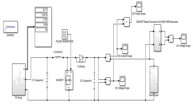
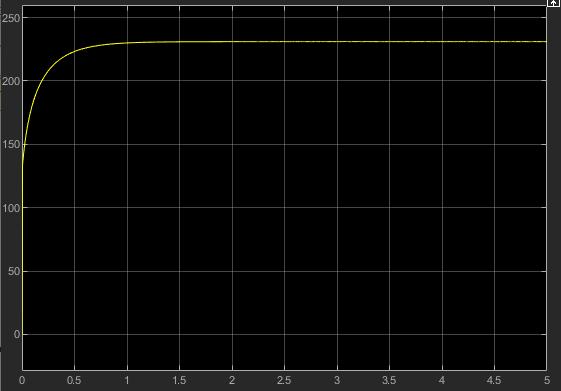
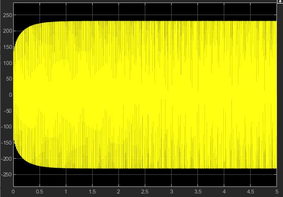
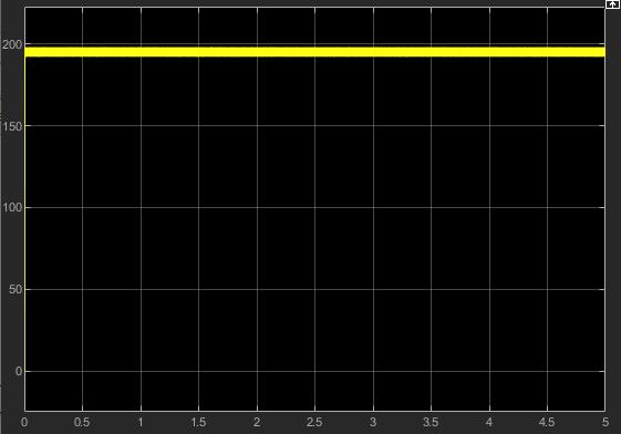
Theparentabovesuggestshowtheevaluationpredictsthe overallperformanceoftheRenewableEnergySource(RES) versionfortheminimalentervoltageVin,min=32.seventy twoVbeneathno-loadsituationswithanoutputvoltageVo= 231.1V.Intheexperiment,theimproveinductanceL=0.001 HandtheresonancecapacitorsC1=33.e-6FandC2=33.e-6 Fhavebeenusedaspassiveparts.Stagesboomtheoutput voltage throughshowing diverse waveformscapturedand not using a load from a low enter voltage (32.72V) to (231.1V).Theoutputvoltagedroppedfrom231.1Vto95.15V whileacompleteloadbecamecarriedouttothecircuit,even as the sun panel voltage dropped from 231.1V to 87.83V. Sincethesunpanelisamodernsource,themodernwithin sidethepanelisconsistentandthevoltage.Weunderstand thatwaterandbloodaresimplyresistiveloads.Therefore,we usearesistorinplaceoftheload,referredtoaselectrolyzer loads.
GraphicallyRepresentation

International Research Journal of Engineering and Technology (IRJET) e-ISSN: 2395-0056
Volume: 12 Issue: 03 | Mar 2025 www.irjet.net p-ISSN: 2395-0072
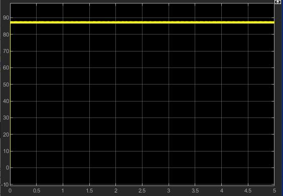
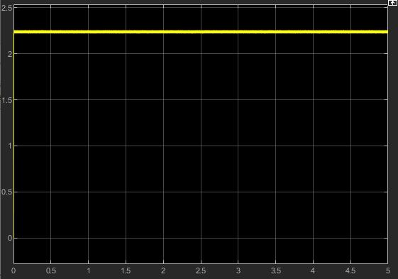
ResultsatVariousLoadLevel
Table2.2:ResultsatVariousLoadLevel
According to the simulation result, this circuit offers a maximumefficiencyof99.19%usingasignalMOSFETwith PWMtechnologyandavoltagedropofupto61.99V.
Thisresearch focusedon the advancement ofeco-friendly, solar-powered electrotherapy devices, integrating modern power electronics technologies and simulation tools like MATLAB.Asolar-poweredsystemwasdesignedtostepup the voltage from 32.71V to 231.1V for electrotherapy applications,utilizingaMOSFET-basedstep-upconverterto achievethe requiredvoltagelevels foreffective treatment. The simulation model successfully demonstrated the conversionofsolarpowerintobothACandDCsignals,with the voltage being stepped up to meet the necessary specifications for electrotherapy. Furthermore, the electrotherapyload,representedbyanelectrozerupto1ohm to 39 ohm, was used to assess the full-load voltage drop 61.99V, providing valuable insights into the system's performance.Maximumefficiencyofthecircuitis99.17%
Thisworkhassuccessfullyestablishedafoundationforsolarpowered electrotherapy devices that are both environmentallysustainableandefficient.Theuseofsolar power, combined with high-efficiency power conversion, holdssignificantpotentialinreducingthecarbonfootprintof traditionalelectrotherapydevices,makingthemsuitablefor useinoff-gridareasandreducingrelianceonconventional power sources. By combining advanced power electronics withsolarenergy,thesystemisnotonlyeco-friendlybutalso highlyadaptabletoawiderangeoftherapeuticapplications.

International Research Journal of Engineering and Technology (IRJET) e-ISSN: 2395-0056
Volume: 12 Issue: 03 | Mar 2025 www.irjet.net p-ISSN: 2395-0072
While this research has demonstrated the effectiveness of stepping up the voltage for solar-powered electrotherapy, there are several areas for future development that could further enhance the functionality and versatility of the system:
1. Voltage Step-Down Conversion: Future work can focusondesigningastep-downconverterthatcan efficiently reduce the voltage levels while maintainingoptimalpowerdelivery.Thiswouldbe particularlyuseful inscenarioswherelow-voltage signals are required for specific electrotherapy treatments.
2. Frequency and Current Control: By incorporating different types of converters, future designs can includethecapabilitytocontrolnotjustvoltagebut alsofrequencyandcurrent.Thiswouldenhancethe system'sversatility,allowingittocatertoabroader range of electrotherapy techniques that require varyingfrequenciesandcurrentstrengths,suchas neuromuscular electrical stimulation (NMES) and transcutaneouselectricalnervestimulation(TENS).
3. AdvancedPowerManagementSystems:Integrating advanced power management systems with feedbackcontrolmechanismswillhelpoptimizethe performance of the solar-powered electrotherapy device. These systems could monitor the battery chargelevels,adjusttheenergyflowbasedonsolar intensity, and improve the efficiency of energy conversionundervaryingenvironmentalconditions.
4. BatteryStorageandEnergyEfficiency:Incorporating batterystoragesystemsintothedesigncouldallow the electrotherapy device to function effectively eveninlowsunlightconditions.Optimizingbattery charging and discharging cycles would ensure continuous availability of power, particularly in remotelocationsorareaswithintermittentsunlight.
5. PrototypeDevelopmentandTesting:Thenextstep involves developing a physical prototype of the solar-poweredelectrotherapydeviceandconducting real-worldtestingtovalidatethesimulationresults. Thiswillprovidefurtherinsightsintothepractical performance,reliability,andefficiencyofthesystem underdifferentoperatingconditions.
Inconclusion,theadvancementsmadeinthedesignofsolarpowered electrotherapy devices in this paper offer a promising pathway toward more sustainable and efficient therapeutictreatments.Future work in voltage regulation, frequencycontrol,andenergymanagementwillsignificantly enhancethefunctionalityofthesedevices,makingthemmore
adaptable and accessible for widespread use in diverse clinicalandhomecaresettings
[1] D. Kornack and P. Rakic, “Cell Proliferation without NeurogenesisinAdultPrimateNeocortex,”Science,vol. 294, Dec. 2001, pp. 2127-2130, doi:10.1126/science.1065467.
[2] D. Kornack and P. Rakic, “Cell Proliferation without NeurogenesisinAdultPrimateNeocortex,”Science,vol. 294, Dec. 2001, pp. 2127-2130, doi:10.1126/science.1065467.
[3] M.Young,TheTechnicalWriter’sHandbook.MillValley, CA:UniversityScience,1989.
R. Nicole, “Title of paper with only first word capitalized,”J.NameStand
[4] Jacopo Martellucci,.“Basic Concepts in Electricity and Electrotherapy” Azienda Ospedaliero Universitaria Careggi.August2015.
[5] David Y, Goodman G. Who represents healthcare engineers? IEEE Engineering in Medicine & Biology Society 11th Annual International Conference, 9-12, Nov.1989.AccessedJuly30,2015.
[6] Mir Sameer Ahma. “A Prefatory Study on Role of Electrical Engineers on Healthcare” International JournalofResearch(IJR).DepartmentofElectricaland ElectronicsL.N.C.TBhopalM.P.April2022
[7] Joshi, P. and Arora, S., 2017. Maximum power point trackingmethodologiesforsolarPVsystemsAreview. Renewable and Sustainable Energy Reviews, 70, pp.1154-1177.
[8] WorldEnergyScenarios:Composingenergyfuturesto 2050.WorldEnergyCongress,Daegu,Korea;2013.
[9] CarlNelson&JimWilliams,“LinearTechnology,LT1070 DesignManual”,1986.
[10] Marty Brown, “Practical Switching Power Supply Design”,NewYork:AcademicPress,Inc.,1990.
[11] Irving M. Gottlieb, “Power Supplies, Switching Regulators, Inverters, & Converters”, New York: McGraw-Hill,1993.
[12] SonuKumar,CSethuramanandChandruGDesignand Development of Micro Off-grid Inverter for Solar PhotovoltaicSystemusingProteusSimulationJournalof Scientific&IndustrialResearchVol.81,May2022,pp. 530-539

International Research Journal of Engineering and Technology (IRJET) e-ISSN: 2395-0056
Volume: 12 Issue: 03 | Mar 2025 www.irjet.net p-ISSN: 2395-0072
[13] Adami,S.E.;Degrenne,N.;Vollaire,C.;Allard,B.;Costa,F. Ultra-lowpower,lowvoltage,autonomousresonantDCDCconverterforlowpowerapplications.InProceedings of the 4th International Conference on Power Engineering, Energy and Electrical Drives, Istanbul, Turkey,13–17May2013.
[14] Alex Q. Huang, Tiefu Zhao, Jun Wang, Jun Li, Xiaohu Zhou.HuangSemiconductorPowerElectronicsCenter Department of Electrical and Computer Engineering North Carolina State University, Raleigh, NC 27695, ‘USA10kVSiCMOSFETBasedBoostConverter’
[15] Abdul Fathah Department of Electrical Engineering NationalInstituteof TechnologyRourkela‘Designofa BoostConverter’departmentofelectrical engineering nationalinstituteoftechnology,rourkelaodisha,india769008
[16] Burin Yodwong, Gianpaolo Vitale, Matheepot Phattanasak,WattanaKaewmanee,DamienGuilbert‘ACDCConvertersforElectrolyzerApplications:Stateofthe Art and Future Challenges ‘Institute for High Performance Computing and Networking, Italian NationalResearchCouncilofItaly,90146Palermo,Italy; gianpaolo.vitale@icar.cnr.it