International Research Journal of Engineering and Technology (IRJET) e-ISSN: 2395-0056
Volume: 12 Issue: 03 | Mar 2025 www.irjet.net p-ISSN: 2395-0072


International Research Journal of Engineering and Technology (IRJET) e-ISSN: 2395-0056
Volume: 12 Issue: 03 | Mar 2025 www.irjet.net p-ISSN: 2395-0072
Sudarshan Suryanarayan1 , Dinesh M Pandit2
1PG M.Tech Student Department Of Civil Engineering,(CSMSS) Chh.Shahu College Of Engg. Chh. Sambhaji Nagar
2Assistant Professor, Department Of Civil Engineering,(CSMSS) Chh. Shahu College of Engg. Chh. Sambhaji Ngar
Abstract - New software is on the market every day. Many structural design software offers in civil engineering. This study uses the new Autodesk Robot structure and Revit Structures -Software to analyze G+20 buildings with or without shear walls. This research provides the use and functionalityofthe abovesoftware. Thisexaminesadvantages and disadvantages, and uses. The growing global population and urbanization will significantly increase the need for skyscrapers. And the safety of these buildings must be considered. The structure ofcultivationcanbeactivelybroken due to wind and earthquake aspects. Security against lateral forces can be achieved by implementing shear walls on the building. Modeling and comparative studies on the stiffness, stiffness and soil shift of the basic scissors of the two models will be carried out in this project using Revit structure and robotic structure software.
Key Words: Autodesk Robot Structural, Revit Structural, Auto-CAD,ShearWall,
Shear walls or structural walls are essential lateral load resistance systems based on high increase for smooth function.Theyprovidethebuildingwiththerightstiffness and stiffness, which reduces the lightness of failure. Positioningshearwallsinadvantageouspositionscanserve asanefficientandeffectivewaytoimprovetheearthquake responseofabuilding.Inthispaper,wepresenttwomodels SeismicZone-IIoftheG+20classifiedframedbuildingsinthe analysis model of the zone. Shear wall on the sides and buoyancy areas. The analysis results of basic shear, floor drift, strong shifting and stiffness of the store give you an idea and important it is to have shear walls in an RCC building,andtheoptimallocationthatcanbeplaced.
1) ToExploreNewSoftwareRobotStructureandRevit Structure.
2) TounderstandtheBehaviourof(G+20)BuildingWith andWith-Outshearwallagainstseismicloading
3) Comparison of Maximum Storey Axial Force, Maximum Storey Moment, storey drift, storey displacementandstoreystiffnessforbuildingswith andwith-outshearwall
4) Advantage and disadvantage in multi-Storey BuildingDesign,UsingTwosoftwarewiththehelpof plug-insoftware.
2. Modeling
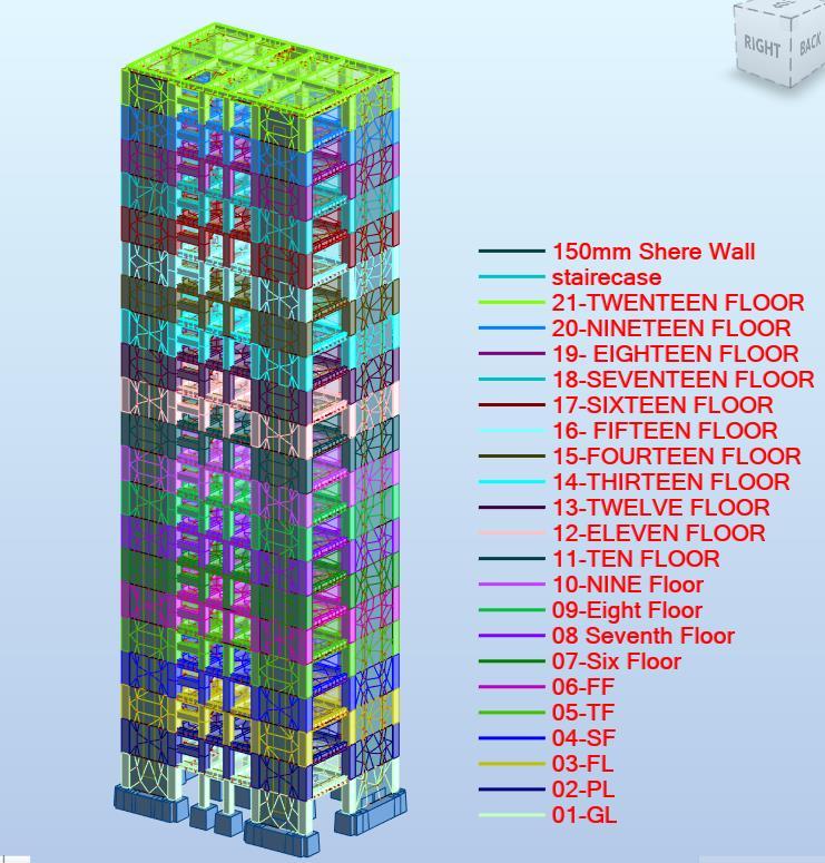
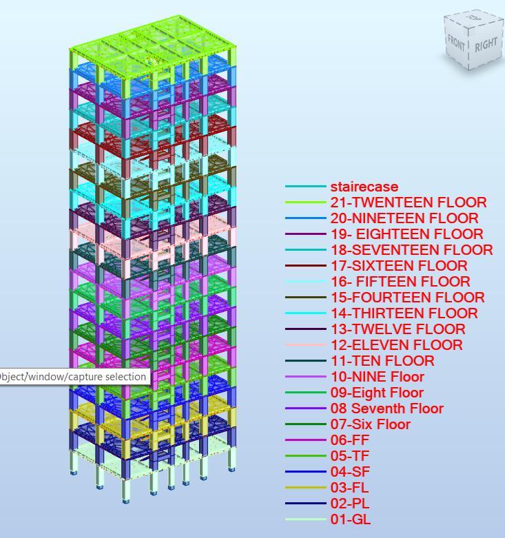
ThisstudymodeledaG+20-storeyframestructurewitha regularplan.Thebuildingisfixedtothebaseandtheflooris thoughttofunctionasaharddiaphragm.Thefloorsurfaceof thestructureis12.80x18.82m.
Model1:-WithShearWall Model2:-With-OutShearWall
Table -1: Building Data

International Research Journal of Engineering and Technology (IRJET) e-ISSN: 2395-0056
Volume: 12 Issue: 03 | Mar 2025 www.irjet.net p-ISSN: 2395-0072


International Research Journal of Engineering and Technology (IRJET) e-ISSN: 2395-0056
Volume: 12 Issue: 03 | Mar 2025 www.irjet.net p-ISSN: 2395-0072

WiththehelpofRevitsoftware,we'vemadealltheframe work exciting, including beams, pillars, plates, basic work. Also material properties, shapes, sizes and creation of a storey G+20 using Revit Software Additionally, Plug-in Autodesk-Robot-Structure software to Revit Software For assignallanalyticalpartialearthquakes,live,dead,andwind loadsaspercodeprovisioningforspecificelementssuchas beamcolumns,slab,andstoreys.Alsothefinalresultsofthis projectasperrobotstructuresoftware.
The analysis results for all two models With Autodesk Robot structures using the Finite Element-method (FEM) methodareobtained.VariationsStandardForAllResultfor allmodelsintabularandgraphicformats
Storeydriftisdefinedastherelativemovementofeach storeywithrespecttoother Table-2 showsthemaximum storeydriftvaluesofeachmodelandfigure-5representsthe variationofstoreydriftingraphicalformat.Theresultsshow that the maximum drift for models without shear walls is largerandlessformodelswithshearwalls.


Storydisplacementisthedeflectionofasinglestoryrelative tothebaseorgroundlevelofthestructure.Table-3shows themaximumstoreydisplacementvaluesofeachmodeland figure-6representsthevariationofstoreydisplacementin graphical format. From the result the maximum storey displacementisseenhigherformodelswithoutshearwalls andlessformodelswithshearwalls

International Research Journal of Engineering and Technology (IRJET) e-ISSN: 2395-0056
Volume: 12 Issue: 03 | Mar 2025 www.irjet.net p-ISSN: 2395-0072


Exact deformation is calculated as based on, node displacements,noderotationsandadvancedinternalfinite element shape functions (corresponding to applied load types)areused.Table-4showsthemaximumstoreyExact Deformationvaluesofeachmodelandfigure-7represents the variation of storey Exact Deformation in graphical format. From the result the maximum storey Exact Deformationisseenhigherformodelswithoutshearwalls andlessformodelswithshearwalls.


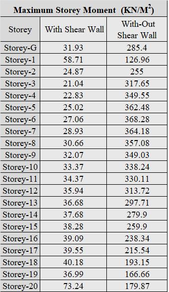
Rotational or bending effect (moment) acting on a building's structure within a single story (or floor level), causedbylateralforceslikewindorearthquakeloads.Table -5showsthemaximumstoreymomentvaluesofeachmodel andfigure-8representsthe variationofstorey moment in graphical format. From the result the maximum storey momentisseenhigherformodelswithoutshearwallsand lessformodelswithshearwalls

International Research Journal of Engineering and Technology (IRJET) e-ISSN: 2395-0056


3.4
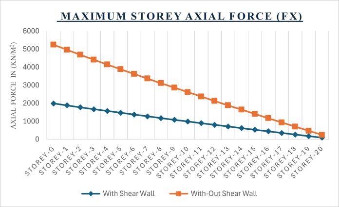
Anaxialforceisaforcethatactsalongthelongitudinalaxis ofabody,eitherpulling(tensile)orpushing(compressive) alongitslength.Table-6showsthemaximum Axial Force valuesofeachmodelandfigure-9representsthevariationof storeyAxialForceingraphicalformat.Fromtheresultthe maximum storey axial force is seen higher for models withoutshearwallsandlessformodelswithshearwalls.


Basedontheanalysisofthetwodifferentbuildingmodels the followingconclusionsaredrawn:
1) Shearwallimplementationreducesthechancesof earthquakefailureinabuildingbyconveyingmore strengthandstiffness.
Volume: 12 Issue: 03 | Mar 2025 www.irjet.net p-ISSN: 2395-0072 © 2025, IRJET | Impact Factor value: 8.315 |

International Research Journal of Engineering and Technology (IRJET) e-ISSN: 2395-0056
Volume: 12 Issue: 03 | Mar 2025 www.irjet.net p-ISSN: 2395-0072
2) Deferral,tierdrift,moments,rayshearforces,colum nmoments,andsupportresponsesareobservedto reducethereductioninshearwallsandsoft storybuildingsonthefirstfloor.
3) Iftheshearwallisaddedintheappropriatelocation andthesamestiffnessinbothdirections,thelocati onoftheshearwallandthelocationoftheshearwa llandthestiffnessoftheshearwallinbothdirectio nsisveryimportant
4) Themaximumdisplacementandmaximumstorey drift is minimum for corner shear walled models. This shows the reduction in the deflection and movement of the G+20 building during seismic activity.
5) Revit's Integrated Professional Plugin to Robot Structure Analysis offers the advantages of optimizing structural analysis and design workflows,improvingadjustments,reducingerrors, and improving structural modeling and analysis accuracy. Automating data transmission and analysisresultsminimizestheriskofmanualerrors andinconsistencies.
6) loadawholestructureinoneprogram,selectapart ofit,andtransferthatparttoanotherSoftware The integration allows for early identification of potential structural issues, enabling engineers to makenecessarydesignchangesbeforeconstruction begins
[1] Ali MM, Moon KS, “Diagrid Structures for ComplexShaped Tall Buildings,” Science Direct, Procedia EngineeringVolume14,2011,Pages1343-1350.
[2] TerriMeyerBoake,Diagrids,theNewStablitySystem: Combining Architecture with Engineering April 2013 DOI:10.1061/9780784412909.056Conference: ArchitecturalEngineeringConference2013
[3] Mashhadiali N, Kheyroddin A, “Introducing an innovative structural system named hexagrid for tall buildingsMay2012Conference:IASS-APCS2012.
[4] MoonKS,ConnorJJ,FernandezJE,“Moon,K.S.,Connor,J. J.,&Fernandez,J.E.(2007).Diagridstructuralsystems fortall buildings:characteristicsandmethodologyfor preliminary design. The structural design of tall and specialbuildings,16(2),205-230
[5] KhushbuJani,PareshV.Patel,2013,AnalysisandDesign of Diagrid Structural System for High Rise Steel Buildings. Elsevier Sciverse Science Direct, Procedia Engineering51(2013)92–100.
[6] Seung Yong Jeong,Thomas H.-K. Kang, Seismic performance evaluation of a tall building: Practical modelingofsurroundingbasementstructures,Science Direct Journal of Building Engineering Volume 31, September2020,101420
[7] James O. Malley, John Wallace,Tall Building Seismic DesignandAnalysisIssues-ATC-72.
[8] M.Surana,Y.SinghandD.H.Lang,SeismicPerformance ofShear-WallandShear-WallCoreBuildingsDesigned for Indian Codes, Department of Earthquake Engineering,IITRoorkee,Roorkee,India.
[9] M. Mosoarca, Failure analysis of RC shear walls with staggered openings under seismic loads, Engineering FailureAnalysisjournal.
[10] A. K. Marsono and S. Hatami, Evaluation of CouplingBeamsBehaviorConcreteShearWallwith RectangularandOctagonal’AppliedMechanicsand MaterialsDept.FacultyofCivilEngineering(FKA), UniversityTeknologiMalaysia

Name:-Sudarshan Suryanarayan. M.Tech Student Department Of CivilEngineering,At(CSMSS)Chh. Shahu College Of Engineering ChatraptiSambhajinagar431001.