ALL FLUID PRESSURE SWITCH, ELECTRO-MECHANICALLY ACTUATED
3
21D 0,1 ... 10,5 bar
Symbol
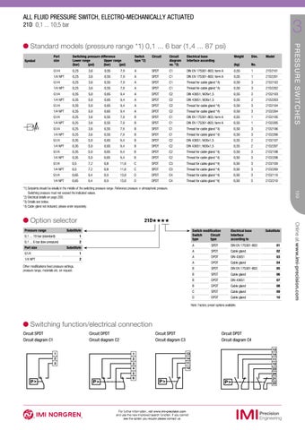
Port size
Switching pressure difference Lower range Upper range (bar) (psi) (bar) (psi)
Switch type *2)
Circuit
Circuit diagram no. *3)
Electrical base Interface according
Weight
Dim.
Model
(kg)
No.
G1/4
0,25
3,6
0,55
7,9
A
SPDT
C1
DIN EN 175301-803; form A
0,55
1
21D2101
1/4 NPT
0,25
3,6
0,55
7,9
A
SPDT
C1
DIN EN 175301-803; form A
0,55
1
21D2201
G1/4
0,25
3,6
0,55
7,9
A
SPDT
C1
Thread for cable gland *4)
0,50
3
21D2102
1/4 NPT
0,25
3,6
0,55
7,9
A
SPDT
C1
Thread for cable gland *4)
0,50
3
21D2202
G1/4
0,35
5,0
0,65
9,4
A
DPDT
C2
DIN 43651; M26x1,5
0,55
2
21D2103
1/4 NPT
0,35
5,0
0,65
9,4
A
DPDT
C2
DIN 43651; M26x1,5
0,55
2
21D2203
G1/4
0,35
5,0
0,65
9,4
A
DPDT
C2
Thread for cable gland *4)
0,50
3
21D2104
1/4 NPT
0,35
5,0
0,65
9,4
A
DPDT
C2
Thread for cable gland *4)
0,50
3
21D2204
G1/4
0,25
3,6
0,55
7,9
B
SPDT
C1
DIN EN 175301-803; form A
0,55
1
21D2105
1/4 NPT
0,25
3,6
0,55
7,9
B
SPDT
C1
DIN EN 175301-803; form A
0,55
1
21D2205
G1/4
0,25
3,6
0,55
7,9
B
SPDT
C1
Thread for cable gland *4)
0,50
3
21D2106
1/4 NPT
0,25
3,6
0,55
7,9
B
SPDT
C1
Thread for cable gland *4)
0,50
3
21D2206
G1/4
0,35
5,0
0,65
9,4
B
DPDT
C2
DIN 43651; M26x1,5
0,55
2
21D2107
1/4 NPT
0,35
5,0
0,65
9,4
B
DPDT
C2
DIN 43651; M26x1,5
0,55
2
21D2207
G1/4
0,35
5,0
0,65
9,4
B
DPDT
C2
Thread for cable gland *4)
0,50
3
21D2108
1/4 NPT
0,35
5,0
0,65
9,4
B
DPDT
C2
Thread for cable gland *4)
0,50
3
21D2208
G1/4
0,5
7,2
0,8
11,6
C
SPDT
C3
Thread for cable gland *4)
0,50
3
21D2109
1/4 NPT
0,5
7,2
0,8
11,6
C
SPDT
C3
Thread for cable gland *4)
0,50
3
21D2209
G1/4
0,65
9,4
0,9
13,0
D
DPDT
C4
Thread for cable gland *4)
0,50
3
21D2110
1/4 NPT
0,65
9,4
0,9
13,0
D
DPDT
C4
Thread for cable gland *4)
0,50
3
21D2210
Pressure range
21D˙˙˙˙
Substitute 1
0,1 ... 10 bar (standard)
2
0,1 ... 6 bar (low pressure) Port size
Substitute
G1/4
1
1/4 NPT
2
Other modifications fixed pressure settings, pressure range, materials etc. on request.
Switch modification Switch Circuit type type
Electrical base Interface according to
Substitute
A
SPDT
DIN EN 175301-803
01
A
SPDT
Cable gland
02
A
DPDT
DIN 43651
03
A
DPDT
Cable gland
04
B
SPDT
DIN EN 175301-803
05
B
SPDT
Cable gland
06
B
DPDT
DIN 43651
07
B
DPDT
Cable gland
08
C
SPDT
Cable gland
09
D
DPDT
Cable gland
10
Note: Factory preset options available.
Switching function/electrical connection Circuit SPDT Circuit diagram C1
Circuit DPDT Circuit diagram C2 1 2 3
P>
P>
Circuit SPDT Circuit diagram C3 1 2 3 4 5 6
Circuit DPDT Circuit diagram C4 13 14 11 12
P>
For further information, visit www.imi-precision.com and use the new improved search function. If you cannot see the option you require please contact us.
P>
13 14 11 12 23 24 21 22
Online at www.imi-precision.com
Option selector
199
*1) Setpoints should be ideally in the middle of the switching pressure range. Reference pressure = atmospheric pressure. Switching pressure must not exceed the indicated values. *2) Electrical details on page 200. *3) Details see below. *4) Cable gland not included, please order separately.
P R E S S U R E S WI T C H E S
Standard models (pressure range *1) 0,1 ... 6 bar (1,4 ... 87 psi)