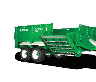
Combi Feedout Wagon RX148 | RX178 | RX218 IMPORTANT Read this manual before operation HUSTLER EQUIPMENT INTERNATIONAL LIMITED
1 CONTENTS Introduction ................................................................................ 2 Important .................................................................................... 2 Specifications ........................................................................ 3-5 Warranty ..................................................................................... 6 Warnings ................................................................................. 7-8 Maintenance ........................................................................ 9-11 Operational Instructions ................................................. 12-17 Trouble Shooting .............................................................. 18-19 Feedlink Trouble Shooting .............................................. 20-21 Register Your Warranty ......................................................... 22 Maintenance log ..................................................................... 23
INTRODUCTION
Thank you for purchasing a HUSTLER COMBI RX MULTl FEEDER WAGON. Please read through this manual as it contains important information which you need to know.
Please take special note of the safety warnings on pages 6-7, routine servicing on pages 8-10, operating instructions on pages 11-15 and troubleshooting on page 16.
Correctly maintained and operated this machine will give many years of service. Should you have any questions please contact the dealer who supplied you this machine. They have trained technicians who will be able to help you.
IMPORTANT
• Please ensure this booklet is read and understood by every operator of this machine.
• Also ensure that this booklet goes with the machine if it is resold and is read and understood by owner.
2
SPECIFICATIONS
Combi Multi Feeder (RX148)
Round Bales
Medium Squares
3-6
6-8
Large Squares (8ft): 6-8
Loose Silage (load-level) 14m3
Loose Silage (Heaped Load) 16.5m3
Maximum Load 10000kg
Overall Width 2950mm
Overall Length 6750mm
Overall Height/loading Height 2430mm
Standard tyres 400 / 60 x 15,5 Flotation Grip
Tread
Axle Tandem Walking beam
Brakes Optional 2 or 4 wheel braking
Weigh Scales Optional Feedlink weighing and feed management system
Floor ( Bed X floor/ Elevator ) 15mm HD Puck Board/ 12mm
HD Puck Board
Chain ( Bed X floor/ Elevator ) Chainless / Twin 12,000lb
Roller Chains/ Twin 12,000lb
Roller Chains
Feed Bars (Bed/ X Floor/ Elevator) Twin Hydraulic Rams/ 65 x 35 RHS / 40 x 40 RHS
Joystick In-cab Electric Control w/ Bales and Silage Mode
Hydraulics Required: 2 pair double acting
Elevator: 1645mm wide chain/slat
Jack: 80mm 2 speed screw, with quick adjustment. Designed strong enough for use as quick hitch stand
3
Combi Multi Feeder (RX178)
Overall Width 3000mm
Overall Length 7820mm
Overall Height/loading Height 2500mm
Standard tyres 500 / 50 x 22,5 Flotation Grip Tread
Axle Tandem Walking beam
Brakes
Optional 2 or 4 wheel braking
Weigh Scales Optional Feedlink weighing and feed management system
Floors (Bed Floor/ Cross Floor): 15mm HD Puck Board/ 12mm HD Puck Board
Chain ( Bed X floor/ Elevator ) Chainless / Twin 12,000lb
Roller Chains/ Twin 12,000lb
Roller Chains
Feed Bars (Bed/ X Floor/ Elevator)
Twin Hydraulic Rams/ 65 x 35
RHS / 40 x 40 RHS
Joystick In-cab Electric Control w/ Bales and Silage Mode
Hydraulics Required: 2 pair double acting
Elevator: 1645mm wide chain/slat
Jack: 80mm 2 speed screw, with quick adjustment. Designed strong enough for use as quick hitch stand
4
SPECIFICATIONS CONT.
3-8
8-10
8-10
Round Bales
Medium Squares
Large Squares (8ft):
17m3
Loose Silage (load-level)
20.5m3
Loose Silage (Heaped Load)
Maximum Load 12000kg
Combi Multi Feeder (RX218)
Round Bales 4-10
Medium Squares 10-14
Large Squares (8ft): 10-14
Loose Silage (load-level) 21.4 m³ | 27.9 yd³
Loose Silage (Heaped Load) 26 m³ | 34 yd³
Maximum Load 17,000 kg | 37,478 lb
Standard tyres 500 / 50 x 22,5 Flotation Grip
Tread
Axle Tandem Walking beam
Brakes Optional 4 or 6 wheel braking
Weigh Scales Optional Feedlink weighing and feed management system
Floors (Bed Floor/ Cross Floor): 15mm HD Puck Board/ 12mm HD Puck Board
Chain ( Bed X floor/ Elevator ) Chainless / Twin 12,000lb
Roller Chains/ Twin 12,000lb
Roller Chains
Feed Bars (Bed/ X Floor/ Elevator) Twin Hydraulic Rams/ 65 x 35 RHS / 40 x 40 RHS
Joystick In-cab Electric Control w/ Bales and Silage Mode
Hydraulics Required: 2 pair double acting
Elevator: 1645mm wide chain/slat
Jack: 80mm 2 speed screw, with quick adjustment. Designed strong enough for use as quick hitch stand
5
Overall Width 3035 mm | 119.4 in Overall Length 9180 mm | 361.4 in
Overall Height/loading Height 2650 mm | 104.3 in
WARRANTY (RX148/RX178/RX218 Feedout Wagon)
The goods specified in the Instruction Manual as designed and supplied by the manufacturer are warranted against faulty workmanship and defective materials for a period of 24 months from the date of purchase.
Such warranty is subject to the following conditions:
1. This warranty covers the repair or replacement of parts or machinery sold by the manufacturer and damaged as a result of the faulty workmanship or materials in such parts or machinery. It does not extend to any other loss or damage including consequential loss or damage or loss to other property or persons.
2. Without limiting the generality of paragraph 1 above, this warranty does not cover the following:
a. Travel expenses.
b. Damage caused by accident, misuse or abuse.
c. Damage to any goods which have been altered or modified by someone other than the manufacturer or its authorised agent
d. Damage or loss to the goods due to their unsuitability for any particular use or for using with any particular tractor except where such use or tractor had been specifically approved by the manufacturer.
e. Damage or loss where the fitting and installation of the goods were not carried out by the manufacturer or its authorised dealer.
f. Paint damage or wear.
g. Wear and tear where Hustler deem the product to be in a high wear environment.
3. Procedure for recovery under warranty. No loss or damage will be covered by this warranty unless the following procedure is followed by the purchaser
a. The loss or damage should be reported immediately to the dealer (who will contact the manufacturer who will advise whether it is covered by the warranty and undertake the necessary action).
“This warranty shall be interpreted according to the laws of New Zealand and the parties agree to submit to the jurisdiction of the Courts of New Zealand.”
6
WARNINGS
• Take EXTREME CARE when connecting the tow bar to the tractor. Ensure the tractor handbrake is applied before leaving the cab. Ensure the correct size drawbar pin and/or Swift Hitch is used.
• Inspect the tow eye for damage or wear BEFORE each use. If using Swift Hitch, ENSURE the hitch safety latch is working correctly and the spring is functioning If the spring fails it could cause the trailer to come disconnected from the tow bar.
• ALL persons must be kept well clear of machine in operation. Only the operator should be within 3 metres of the machine during operation.
• Watch CAREFULLY when driving for over-width and tail-swing when travelling through gateways or near objects or people.
• Always BE AWARE of your surroundings, this is a large machine with blind spots, make sure you always know where persons and stock are.
• If the tow bar is connected to a tractor, BEFORE attempting maintenance or any work, ensure the tractor engine is shut off and no one is near the hydraulic controls.
• DO NOT allow any person(s) to ride on the tow bar or trailed machine at ANY time.
7
WARNINGS CONT.
• ALWAYS lift the tow bar to the correct height specified in the ‘Operating Instruction’.
• Take EXTREME CARE when towing over uneven or sloped ground. The angle changes the balance point and could tip the vehicle over. The tractor and trailer manufacturer capacity and angle ratings must be adhered to.
• NO alteration or modification is to be done on this machine unless undertaken or authorised by Hustler. This will void warranty.
• KEEP CLEAR of moving parts of the machine. There are many areas that may pinch a hand, fingers or body parts.
• REGULARLY check the machine for signs of wear, stress or damage. ENSURE any parts are repaired/replaced if needed.
• ENSURE the trailer jack is lifted high enough to clear the ground when driving over uneven ground.
• Hustler Equipment recommend using a rated safety chain from the trailed unit to either the tractor or the SWITCH HITCH. It is for the operator to check the law of their country/state regarding towing a trailer unit Hustler Equipment do not recommend driving over undulating terrain or on public roads using the SWIFT HITCH.
8
MAINTENANCE
(also do this before initial operation)
• Grease all (21) grease points, grease the swivel hitch regularly

• Check and adjust all conveyor and elevator chains. The cross floor should be just lifted of the return rail underneath the centre of the cross floor. Elevator chain should be just hanging below catcher, between 5 and no more than 10mm between roller and return rail.
• After the first 10 hours of operation check chain tensions, joiners Elevator tilt ram pins and clips. Check for oil leaks, loose bolts. Check wheel bearings are tight, wheel nuts are tight. Check correct level oil in gearbox’s.
• During routine servicing check chain tensions, wheel bearings, all conveyor shaft bearings, oil level in gearbox drive.
• Check for damaged electrical wiring around the drawbar / tractor area, check correct functionality of the electric controls.
• Oil chain rollers regularly
• Wheel bearings to be greased during routine checks or at minimum annually
• Regularly check the machine for signs of wear, stress or damage. Ensure any parts are repaired/replaced if needed.
• Long Term Storage, leave pusher in the forward position, lower elevator into the out/down position, this is to keep ram shafts protected inside their ram bodies.

9
Cross floor chain just lifting off bottom Elevator chain underneath 5 to 10mm gap Rear Bed Floor chain just lifting off bottom guide
MAINTENANCE CONT.
• Rear Bed Floor gearbox Oil level use SAE 90 gear oil. 3.9 Litre from Empty
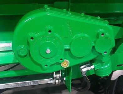

• Cross Floor gearbox Oil Level use SAE 90 gear oil. 2.8 Litre from empty. Always check level when hydraulic motor is Horizontal.
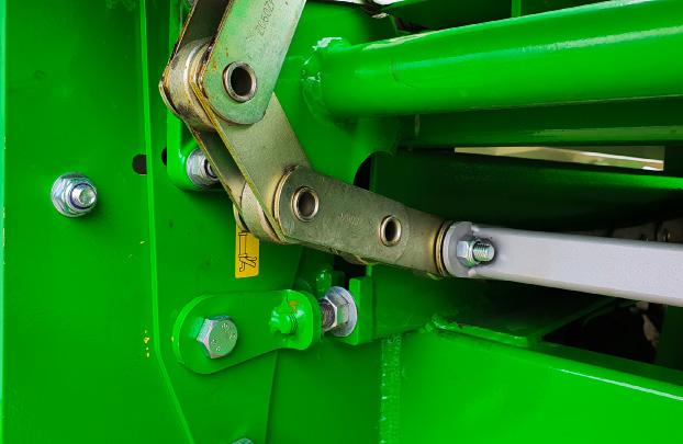
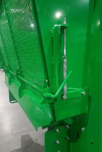
• Tail Gate Latch Adjustment Factory set to 30mm thread as shown, if gate open to easily tighten spring tension untill required tension is obtained
10
Rear Bed Floor Drive Gearbox Oil Level, Centre line of shaft
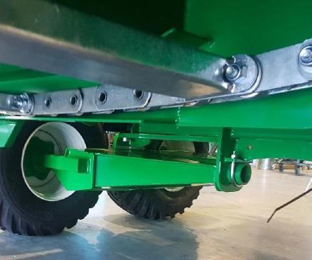
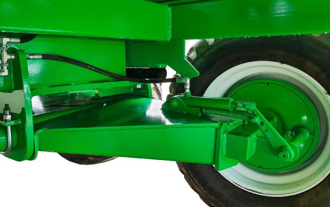
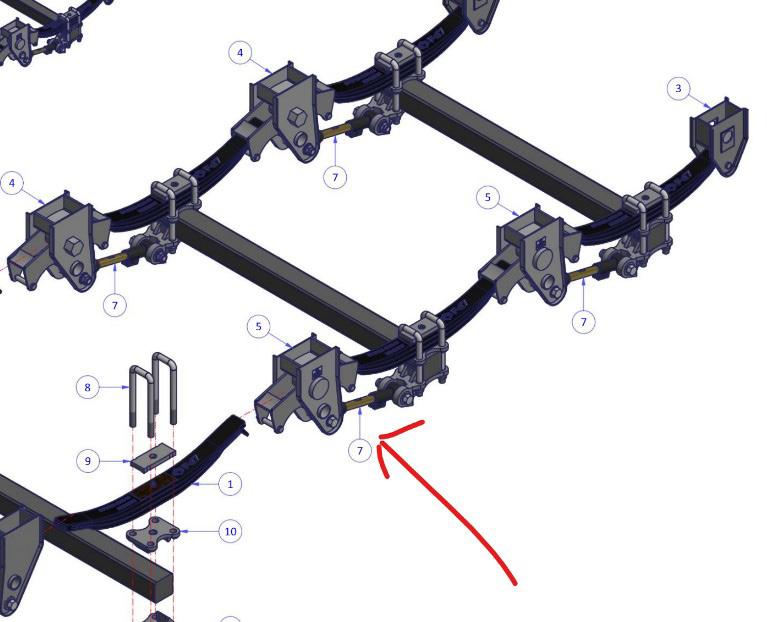
• After the first 10 hours of use, check that the adjustable tie rods locking bolts & nuts are tight. Loctite & tighten if loose.
Brake Adjustment
• Brakes are pre-set at the factory, but as things wear, some adjustments can be made. The brake lever is fitted onto a splined shaft. To adjust remove this lever, turn slighty towards the brake ram and re fit on the next spline, this is still not enough adjustment, then repeat until adjustment is reached.

Critical Bolt Torque settings
Drawbar
• Tow eye, M16 Cap Screws, torque to 200 N.m
Load Cell
• M24 x 70 Hex head grade 10.9 bolts, torque to 822 N.m
• M24 x 110 Hex head grade 8.8 bolts, torque to 600 N.m
Axle load Cell
• M24 X 70 Cap Screws grade torque to 12.9 950 N.m
• M24 x110 Hex head grade 8.8 bolts, torque to 600 N.m
Axle Wheel Nuts
• M18 std torque to 269NM
• M20 torque to 372NM
11
Splined Shaft
Brake Lever
OPERATIONAL INSTRUCTIONS
Joystick/ Feed Control
Controls
Name
Thumb stick up X floor feed
Thumb stick down X floor reverse
Thumb stick left
Thumb stick right
Rear bin forward
Rear bin reverse
Thumb stick button Elevator pause
Switch left
Switch right
Silage mode (auto) *
Bale mode (manual) *
* Bottom Switch ‘left’ joystick only operates in “ Silage mode’ when optional Feed Control load sense valve is fitted.

* Bottom Switch ‘Right’ Joystick operated as manual control only, when optional Feed Control load sense valve is fitted, or standard valving fitted.
Connection Procedure - to be carried out with an empty machine
• Connect machine to a suitable tractor rear tow hitch or a Hustler
SwiftHitch
• Connect the two larger hydraulic hoses to bank 1 of the tractor that has a detent control. Connect the two smaller hoses to bank 2 of the tractor.
• Fix the electric controller securely in the tractor cab, Connect the incab controller to the machine. Connect the controller to 12vDC power.
• Operate hydraulic bank 2 to adjust the elevator tilt angle.
• Operate hydraulic bank 1 ensuring the elevator chains are running in the correction direction to feed out.
12
Silage Mode (switch left)
• The elevator will run continuously while bank 2 is active.
• The X floor will run in the feed direction when bank 2 is active. If the X floor does not move, see the Hydraulic Adjustments section of this document to increase the amount the x floor moves.
• Operating the joystick on the controller will activate the rear bin and X floor in the desired direction, overriding the standard feed control movements.
• Press the button on the end of the joystick to intermittently decrease the elevator speed.
• Reverse the elevator chain direction by operating bank 2 in reverse.
• The elevator speed may decrease when the rear bin function is active. this can be altered to the operator’s preference following the procedure in the Hydraulic Adjustments section of this document.
Bale Mode (switch right)
• The elevator will run continuously while bank 2 is active.
• Operating the joystick on the controller will activate the rear bin and x floor in the desired direction.
• Press the button on the end of the joystick to intermittently decrease the elevator speed.
• Reverse the elevator chain direction by operating the bank 2 in reverse.
• The elevator speed may decrease when the rear bin function is active. This can be altered to the operator’s preference following the procedure in the hydraulic adjustments section of this document.
13
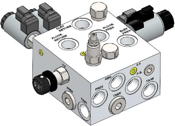
Hydraulic Adjustments
• Black knob (Blue Arrow) - Feed Control pressure. Factory settong = 4 turns counter - clockwise from closed (in).
• Turn the black knob clockwise to increase the amount that the x floor moves. This will increase the amount of material feeding onto the elevator.
• Allen key (Orange Arrow) – Rear Floor Speed. Factory setting = 1 turn & 5 flats (300°) counter-clockwise from closed (in).
• Turn the allen key counter-clockwise to increase the rear floor speed. Increasing the rear bin speed will decrease the elevator speed, only when the rear bin is activate.
• Allen Key (Green Arrow) – System pressure. Factory setting 2050 psi = 4 turns counter-clockwise from closed (in). Approximately 5 threads out past the backing nut (red arrow). Before adjusting attach a pressure gauge to the port shown with a yellow arrow below. Fully extend the pusher ram and check the pressure reading. This must not exceed 2500psi (172 bar).
14
OPERATIONAL INSTRUCTIONS CONT.

15
OPERATIONAL INSTRUCTIONS CONT.
Do
• Use a tractor big enough for the job, have at least 80 Litres per minute oil flow and always drive safely to the conditions.
• Drive slowly when loaded
• Connect the drawbar to tractor via drawbar or SWIFT HITCH.
• If using a SWIFT HITCH, with the tractor and trailed unit sitting on level ground, lift the SWIFT HITCH up to make the trailed unit level.
• Ensure the trailer jack is lifted well clear of the ground so it will not hit when on uneven ground.
• We recommend a safety chain is connected from the trailer to either the SWITCH HITCH or the tractor.
• Clean the hydraulic connectors and couple to tractors hydraulic banks, Elevator tilt hoses into bank 1 and the machine into bank 2. NB when disconnecting the Tilt hoses (one with tap) always turn tap off before disconnecting and tap remain off until reconnected
• Connect the electric control and lights if fitted.
• Adjust tractors hydraulic flow to 60-80 Litres per minute.
• Check direction of elevator rotation prior to feeding.
• Load feed material in to machine. Note when feeding silage material load the Cross-Feed Chamber and Bed Storage Chamber separate to minimize knitting together of long material across the compartments. This decreases the pressure on the drives to separate the load when feeding out with the cross-feed chamber.
• Tie strings to side rail though slots in side panels
16
Do Not
• Tow this machine on a slope greater than 12deg.
• Operate the X-Floor or the Bed Storage Floor in the backward direction with material in the machine.
• Travel with the elevator down/out unless feeding out at very slow speeds’
• Actuate the control levers backward and forwards to ‘free’ the load if the floor or elevator chains become jammed. As this can cause damage to drives and hydraulics.
• Overload the machine with material.
• Use the elevator in the traveling position to feed out. Always extend the elevator out to feed. Note if the bed storage chain fails to move, extend the elevator fully so the rear flaps are out of the machine then retract into feeding position.
• Ride on any part of the machine while traveling
• Water blast the load cell head unit, load cells or junction box.
• Apply excessive material pressure on to elevator with Cross-Floor load.
• Weld on the machine with a load cells fitted.
• Leave strings in machine during or after operation.
• Overload your machine, check model specifications for correct loading capacity.
• Exceed 30Kph when loaded, and only 40Kph max when empty.
• Bring load forward compacting into feeding chamber against front fence, this will result in difficult product flow on cross floor and elevator.
• Load above sides unless on flat ground as product may fall, maximum permissible load above sides on flat ground is not more than 600mm..
17
TROUBLE SHOOTING
General Issues
ISSUE
Elevator won’t tilt
POSSIBLE CAUSE SOLUTION
• Hydraulic Hoses not plugged into tractor correctly
• Jammed Elevator
• Bent Ram
• Oil flow from tractor too low
• Clean and plug into tractor correctly
• Check for foreign objects in elevator body
• Increase oil flow to 50-80 Litres
• Replace Ram
Elevator won’t start
• Hydraulic Hoses not plugged into tractor correctly
• Jammed Chains
• Oil flow from tractor too low
• Clean and plug into tractor correctly
• Check for foreign objects in elevator chains
• Increase oil flow to 50-80 Litres
Elevator works but Cross Floor won’t go in one or either direction
• No power at electric controller
• Jammed Chains
• Damaged wiring
• Defective Coil on valve
• Check power fuse, power at controller
• Check for foreign objects in Cross Floor chains
• Check Controller plugged into machine
• Check electrical cabling for damage
• Replace Coil
Tail Gate opens unexpectedly
Cross floor won’t stop
Elevator stall
• Broken catch latch spring
• Latch spring tension to lose
• Feed controller switch in (silage mode)
• Replace the Latch spring
• Tighten Latch spring tension
• Switch to bale mode
Feed Controller does not work
Joystick Controller does not work
Weighing system Not Working
• Oil flow, pressure from tractor too low
• Cross floor speed set to high
• Pause button presses
• Not plugged into wagon
• Damaged wiring
• No power
• Not plugged into wagon
• Damaged wiring
• No power
• Battery flat
• Out of range
• Device not connected
• Increase oil from tractor
• Adjust feed control to slow cross floor
• Release pause button
• Plug it in
• Check wiring
• Check power supply
• Plug it in
• Check wiring
• Check power supply
• Check battery voltage, should be 3.6V replace if voltage low.
• Move closer and try again
• Check settings and re connect, also check
• 31uetooth in turned on in device
18
Feed Control Issues (Silage Mode)
ISSUE POSSIBLE CAUSE SOLUTION
Too much material being feed
Not enough material being feed
• Elevator running too fast
• Feed control setting too high
• Elevator running too slow
• Feed Control setting too low
• Decrease oil flow
• Adjust Feed Control down
- Black Knob clockwise
• Increase oil flow
• Adjust Feed Control up
- Black Knob counterclockwise
Cross floor not moving
Cross floor won’t stop
Pusher moving too fast
Pusher moving too slow
Pusher not moving
• Feed Control setting too low
• Feed Control setting too high
• Rear bin speed too high
• Rear bin speed too low
• Rear bin speed too low
• Pressure relief valve to low
• Adjust Feed control up Black Knob clockwise
• Adjust Feed ControlBlack Knob Clockwise
• Adjust Rear Floor speed down - Allen key clockwise
• Adjust Rear Floor speed up - Allen key clockwise
• Adjust Rear Floor speed up - Allen key clockwise
• Increase pressure relief
- Black valve allen key counter - clockwise ( 1/4 turn at a time) Check Adjustments section of this document before adjusting
19
FEEDLINK SCALES & FEED MANAGEMENT SYSTEM
Phantom/Erratic Loads
If the Feedlink app records phantom loads, there may be an issue with the load cell(s).
1. Ensure the wagons load cell junction box cable is connected and secured to the Feedlink device.
2. Inspect all the wiring and junction box connections. Check for any cabling that is rubbed, damaged, or pinched.
3. Assuming there is a stable weight when the wagon is parked, apply weight (perhaps your body weight) to each of the cart’s load cells to ensure the scale weight goes up by the same amount no matter where weight is added on the cart. This verifies there is an equal signal from all load cells.
4. If the weight is not stable when parked, start disconnecting one load cell at a time from the junction box. This should point towards the source of the wondering signal.
5. If a faulty load cell or cable isn’t obvious, it could be a junction box issue. Check for corrosion on the circuit board or moisture inside if the junction box is an open enclosure (screw terminal) style.
20
Bluetooth Pairing Issues
• Ensure the app is running the latest version from the Apple App Store or Google Play.
• You are attempting to pair from the Equipment/Settings tab of the Feedlink app and not the general tablet/smartphone Bluetooth settings.
• Bluetooth is enabled on the mobile device.
• Primary Display is selected in the Settings tab when pairing the main mobile device in the grain cart. If attempting to pair a remote display, ensure that the primary display is already paired and communicating.
• There are no other mobile devices paired to the Feedlink device as the primary display.
• The device is not already listed under Paired Devices in the Equipment tab of the Feedlink app. If the device is listed, but there is no checkmark beside the cart name, tap the name to reconnect.
• The battery inside the Feedlink device is well seated with correct polarity and does not need replacing. Next to the battery terminal on the circuit board, a small light will flash once every 10 seconds if the Feedlink device is getting power. If using the power cable, inspect the cable and ensure it is secured to the Feedlink device.
• There is no moisture or corrosion on the circuit board, and all wires are connected inside the Feedlink device.
• If still unsuccessful, try the following:
• Turn Bluetooth off and then on on the mobile device (under general Bluetooth settings).
• Turn airplane mode on and then off on the mobile device.
• Restart the mobile device.
• Remove the battery, wait a full 60 seconds and then reinsert.
• Try another compatible mobile device.
21
REGISTER YOUR WARRANTY
Register your warranty online!
Scan the QR Code to register your warranty. Or visit www.hustlerequipment.com/warranty
Follow our 3 easy steps:
1. Dealer or end user? Click which applies to you.
2. Follow the instructions and fill out the info required
3. Submit your form!
Note: The machine is NOT covered by warranty until the EUSA Product Registration form and your warranty form is completed!
22
MAINTENANCE LOG
This record is to stay with the instruction manual and be used as proof of upkeep should a claim be lodged. Hustler requires you to keep track of approx 12 monthly maintenance by having your service provider routinely fill out the log, or by keeping receipts of work done. Routine checks will save ongoing repair costs. Pre-season is the best time for this. Excluded items are wear parts and electric components.
Purchase Date ____________________ Machine serial number ___________
SERVICE 1 (12-15 MONTHS FROM PURCHASE DATE)
Date of service
Number of bales / hectares sprayed
Signature and Dealer Name
SERVICE 2 (24-30 MONTHS)
Date of service ____________________
Number of bales / hectares sprayed ___________________________________
Signature and Dealer Name ____________________________________________
SERVICE 3 (36-42 MONTHS)
Date of service
Number of bales / hectares sprayed
Signature and Dealer Name
SERVICE 4 (48-55 MONTHS)
Date of service ____________________
Number of bales / hectares sprayed ___________________________________
Signature and Dealer Name ____________________________________________
CHECKLIST
Grease all nipples
All fastenings tight
Wear parts replaced (bushes, cables etc. are not covered items)
Secure all hoses and clamps
Drive components not wobbly
Wash down + Throughly
Inpect Machine
Chassis/boom Hairline Cracks repaired
General Inspection of construction
23
NOTES
24
NOTES
25
FEEDOUT WAGON
NEW ZEALAND - GLOBAL HQ
Free call: 0800 487 853
Email: sales@hustlerequipment.com
After sales: 06 873 9520
1287 Omahu Road
Hastings, 4153 New Zealand
AUSTRALIA HQ
Free call: 1800 750 428
6 Ravenhall Way, Ravenhall, Melbourne, VIC 3023
NORTH AMERICA HQ
Office: (612)-351-4885
21405 Hamburg Ave, Lakeville, Minnesota 55306
USA
UNITED KINGDOM HQ
Phone: 01563 481 330
International House, Rowallan Business Park, Southcraig Ave, Kilmarnock KA3 6BQ, United Kingdom
EUROPE HQ
Phone: +33 4 71 59 51 86
Z.A. le Fieu 43190 Tence

France
www.hustlerequipment.com
COMBI RX148 | RX178 | RX218
