
4 minute read
Group 23 Fuel SystemRepair instructions

from Volvo Penta TAD1240GE TAD1241GE-VE TAD1242GE-VE, TWD1240VE Group 22-26 Workshop Manual_381897674

Bypass valve, changing
1
Clean thoroughly around the bypass valve.
2
Drain the fuel system, See “Fuel system, draining.” 3 (TAD)
4
Clean the connectors on the fuel hoses. Install a new bypass valve and gaskets. Torque to 55 ± 5 Nm (40 ± 4 ft-lbf)
5
Bleed the fuel system. See “Fuel system, bleeding.”
6
Run the engine at fast idle for about 10 minutes to evacuate any remaining air from the system.
7
Perform a leakage check.
Remove the bypass valve. 3 (TWD)
Remove the bypass valve.
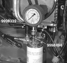
Fuel pressure, checking
Special tools: 9998339, 9998494
1
Clean the fuel filter bracket carefully.
2
Remove the bleed nipple and install connector nipple 9998494. Connect pressure gauge 9998339.
3
Start the engine and run it at 1000 RPM until the fuel pressure on the pressure gauge has stabilized.
4
Compare the measured pressure with the fuel pressure given in the table below.
Fuel pressure
After fuel filter at 1000 RPM, min350 kPa (50 psi)
After fuel filter at full load, min350 kPa (50 psi)
5
When the check is completed, remove the measurement equipment and bleed the fuel system. See “Fuel system, bleeding.”
Unit injectors, changing
Specialtools:9998249,9998250,9998251,9998255, 9998511
Otherspecialequipment:9812546
Remove valve cover.
NOTE: Do not use air tools as the studs can come loose and the injector wiring insulation can be damaged.
Lift out the rocker arm bridge using lifting bar 9998255.
NOTE: If no lifting bar is available, the rocker arm bridge should be lifted by two persons to avoid injury and damage.
4
Drain the fuel from the cylinder head as instructed. See “Fuel system, draining”.
5
Clean very carefully around the injectors to be replaced.
Remove all the adjustment bolts for the rocker arms and the valves. Remove all the bolts on the rocker arm bridge.
NOTE: Loosen the bolts on the rocker arm bridge evenly along the entire bridge to avoid distortion.
Install 2 ea. ring seals 9998250 in the cylinder head fuel groove.
NOTE: Be sure that the sealing rings are well cleaned and correctly seated. 9
Disconnect electrical wires from the injector.
IMPORTANT! Be careful when connecting or disconnecting the wiring to the injectors.
Clean the copper sleeve. Use a hand drill and cleaning brush 9812546.
Remove the injector using pry bar 9998511 if required.
Check that no contamination gets down into the fuel chamber in the cylinder head. Install protective sleeve 9998249 onto the injector.
Clean the injector hole in the cylinder head very carefully and remove sealing rings 9998250.
11
Install new sealing rings on the injector and check that they are correctly seated.
Lubricate the rings with engine oil. Install the injector, forcing it down until it seats and center it between the valve springs. Tighten the injector to the torque and angle specified. See “Technical data TAD1240GE, TAD1241GE/VE, TAD1242GE/VE, TWD1240VE”.
NOTE: Different tightening torques apply depending on whether or not the injector’s copper sleeve has been replaced.
If the injector is not installed immediately, insert a protective plug 9998251 into the cylinder head hole.
13
Connect the electrical wires to the injector and tighten the nuts to max. torque 1.5 Nm (1 ft-lbf).
NOTE: If the nuts are overtightened, the solenoid valve can be damaged and the entire injector will have to be replaced.

Oil the valve yokes and cams with engine oil. Lift the rocker arm bridge into position using lifting bar 9998255.
Be sure that the valves and rocker arms mate correctly. NOTE: If no lifting bar is available, the rocker arm bridge should be lifted by two persons to avoid injury and damage.
Adjust the valves and injectors. See “Valves and unit injectors, adjustment”.
Tighten the bolts on the rocker arm bridge evenly along the entire bridge to avoid distortion.
Be sure that the rocker arm shaft fits correctly into the guide sleeves on the camshaft bearing blocks and tighten the bolts so that the shaft is snug against the bearing blocks.
Then tighten the bolts on the rocker arm bridge to the torque specified in the tightening instructions. See “Technical Data TAD1240GE, TAD1241GE/VE, TAD1242GE/VE and TWD1240VE”.
Install the valve cover and torque the nuts to 20 ± 2 Nm (15 ± 2 ft-lbf) in the order shown in the diagram.
NOTE: It is important to torque the valve cover nuts as shown in the diagram to avoid cracking the cover and to prevent the studs from loosening in the cylinder head.
If any stud in the valve cover came loose from the cylinder head when the nuts were removed, check the wiring insulation by the injectors. There is a risk that the cable holder on the stud will twist and damage the wiring insulation.
18
If any stud has come loose, it must be removed, cleaned and coated with locking compound item no. 1610532 before being replaced and tightened. Do not loosen the stud bolts or nuts until the locking compound has set.
NOTE: Install the studs within 20 minutes after applying the locking fluid.
19
Bleed the fuel system. See “Fuel system, bleeding”.
20
Run the engine at fast idle for about 10 minutes to evacuate any remaining air from the system.
21
Perform a leakage and function check.
Draining condensate water
1
Fuel pre-filter with water monitor, changing
1
Clean around the fuel filter.
2
Disconnect the water monitor.
3
NOTE: Place a container under the fuel pre-filter to collect the condensate water and fuel.
Open the drain nipple at the bottom of the fuel pre-filter and let the condensate water run out.
2
Tighten the drain nipple when water-free fuel runs out.
3
Start the engine and let the engine fill the water separator with fuel. Let the engine run for 10 minutes at idle so that any air remaining is forced out of the fuel system.
4
Shut down the engine and check for leaks.
Drain the fuel filter, see “Fuel system, draining”.
4
Remove the fuel filter with an appropriate filter wrench.
NOTE: Unless the entire filter unit with water monitor is to be replaced, the water monitor should be transferred to the new fuel filter.

5
Clean the filter contact surface on the filter housing.
6
Spread a thin layer of engine oil onto the sealing ring and install the new fuel filter according to the instructions on the filter.
7
Connect the water monitor.
8
Start the engine and check for leaks.


