14 minute read
Functions of and How to Use User Mode ( TR-150-4/GR-150-1 )


How to Use the Working Range Limit Function
[NOTICE]
If the working range limit is registered very close to an obstacle, there is a risk of the crane colliding with the obstacle, depending on the operational status and the manner in which the load is handled. When registering a range limit, allow a sufficient clearance to avoid collision.
The working range restricting function makes the boom automatically stop at the previously registered boom angles (upper and lower), lifting height, load radius and swing angle, The function is useful for handling a load in a confined place because it defines the area in which the boom can operate.
[NOTICE]
Turning the power off (PTO switch: OFF) automatically erases all the previous settings stored in memory after approximately 2 hours. To resume the operation more than 2 hours after the power has been last turned off, enter the settings all over again.
Boom Angle Limit
Raise or lower the boom to the desired angle, and press the upper or lower boom angle restriction key. The corresponding restriction indicator lamp will flash and the buzzer will sound continuously, indicating that the boom angle limit has been registered in the memory. When the boom is moved back to an angle within the set limit, the restriction indicator lamp stops flashing and stays lit and the buzzer stops. Thereafter, the upper or lower boom angle restriction indicator lamp flashes and the buzzer sounds continuously whenever the upper or lower limit previously registered is reached. (Boom raising or lowering stops automatically.)
To cancel the boom angle limit function, press the boom angle restriction key again. The corresponding boom angle restriction indicator lamp will go off.
Upper boom angle restriction indicator lamp
Lower boom angle restriction indicator lamp
Lower boom angle restriction key
Upper boom angle restriction key
IW301-0134E05
Functions of and How to Use User Mode ( TR-150-4/GR-150-1 )
Lifting Height Limit
Move the boom to the desired height, and press the lifting height restriction key. The lifting height restriction indicator lamp will flash and the buzzer will sound continuously, indicating that the height limit has been registered in the memory. When the boom is moved back to a height within the set limit, the lifting height restriction indicator lamp stops flashing and stays lit and the buzzer stops. Thereafter, the lifting height restriction indicator lamp flashes and the buzzer sounds continuously whenever the height limit previously registered is reached. (Boom raising and extending stop automatically.)
To cancel the height limit function, press the lifting height restriction key again. The lifting height restriction indicator lamp will go off. °
Lifting height restriction indicator lamp
Lifting height restriction key
Swing Limit
Swing the boom to the desired position, and press a swing restriction key. The corresponding swing restriction indicator will flash and the buzzer will sound continuously, indicating that the swing angle limit has been registered in the memory. When the boom is swung back to an angle within the set limit, the swing restriction lamp stops flashing and stays lit and the buzzer stops. Thereafter, the swing restriction indicator lamp will flash and the buzzer will sound whenever the limit previously registered is reached. (Boom swinging stops automatically.)
To cancel the restriction function, press the corresponding swing restriction key again. The corresponding swing restriction indicator lamp will go off.
[NOTICE]
When registering a swing angle limit, register both the right and left swing limits, one-side registering is dangerous because an automatic stop is not made when the boom approaches the limit position from the opposite direction.
Left swing restriction indicator lamp
Right swing restriction indicator lamp
IW301-0131E72
Right swing restriction key
Left swing restriction key
IW301-0131E73
Functions of and How to Use User Mode ( TR-150-4/GR-150-1 )
Load Radius Limit
Move the boom to the desired load radius, and press the load radius restriction key. The load radius restriction indicator lamp will flash and the buzzer will sound continuously, indicating that the load radius limit has been registered in the memory. When the boom is moved back toward the non-critical side, the load radius restriction indicator lamp stops flashing, and stays lit and the buzzer stops.
The load radius restriction indicator lamp flashes and the buzzer sounds continuously whenever the limit previously registered is reached. (Boom extending and lowering stop automatically.)
To cancel the load radius limit function, press the load radius restriction key again. The corresponding load radius restriction indicator lamp will go off.
Functions of and How to Use User Mode ( TR-150-4/GR-150-1 )
Display of Working Range Limit Values
Press the register key while working range limits have been registered. While the key is being pressed, the registered working range limit values are displayed. On the moment display will be displayed a message "Working range".
[NOTICE]
This display is not made during a preoperational check of the AML and when a working state is being registered. When working range limits are not registered, the message " " will be displayed.
Upper limit values
Functions of and How to Use User Mode ( TR-150-4/GR-150-1 )
Display Alteration
Displays on the moment display and the display panel 1 can be altered, as shown below in the figures, by pressing the display alteration key. The indicative symbols are displayed, too.
Moment
IW301-0131E76
Display Panel 1
[NOTICE]
Displays on the actual load display and the rated load display do not alter even when the display alteration key is pressed.
IW301-0134E07
Functions of and How to Use User Mode (GR-600-1/ GR-800-1)
Functions of and How to Use User Mode (GR-600-1/ GR-800-1)
Mode Structure
The AML device has three modes and AML functions are allotted for these models.
2. Maintenance Mode:
Used to make functional checks of AML. See the “ADJUSTMENT AND MAINTENANCE” section.
3. Adjustment Mode:
Used to make detector adjustment. See the “ADJUSTMENT AND MAINTENANCE” section.
1. User Mode:
Used to indicate moment ratio or to perform AML pre-opetational inspection (Normally used).
In normal use, turn ON the protect switch mounted on the adjustment window on the top of AML. AML will go to the user mode when the power turns on.
The abnormality display LED lights when the AML is in abnormal conditions (to indicate that the CPU is faulty).
Functions of and How to Use User Mode (GR-600-1/ GR-800-1)
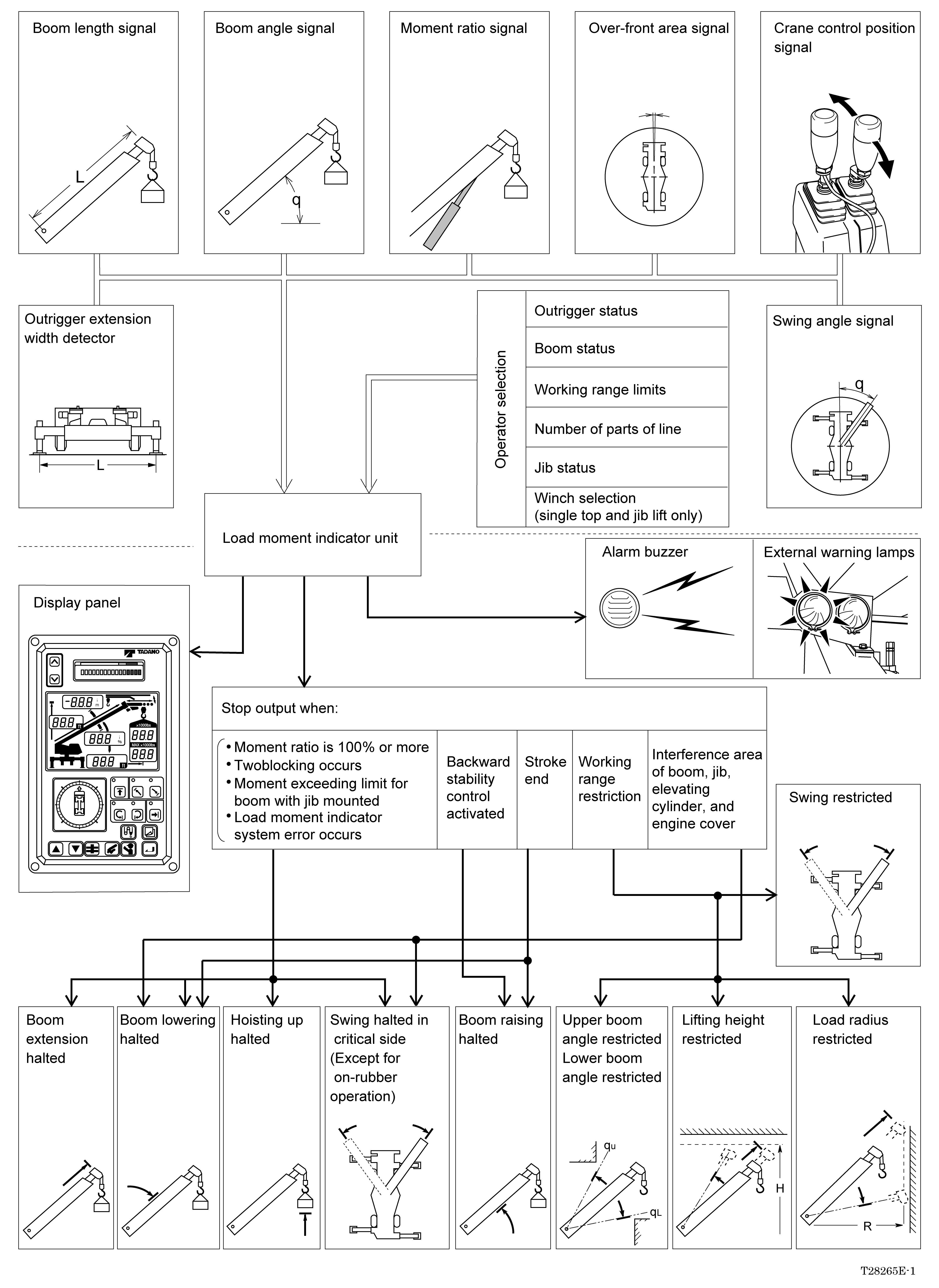
Configuration and Functions of the AML System
The AML system is a safety device provided to prevent overloading of the crane which may cause it to overturn or be damaged. The AML system has various kinds of functions, including the following typical functions. Based on the registered work conditions by operator selection and the signals from various sensors, the crane operations are controlled.
(1) Automatic stop function to prevent overloading
The AML calculates and compares the working and rated moment values and displays their ratio. When the working moment exceeds the rated moment (100% or more), failure message is shown, alarm buzzer sounds, and the crane operation toward the critical side stops.
(2) Automatic stop function by backward instability
When the boom is raised to [77°: TR-600XXL-4 (69°:TR-800XXL-4)] in an over-side area with on-rubber operation.
(3) Working range limit functions
When any working range limit is registered to the AML, the crane is controlled so that the crane work posture does not exceed this registered working range limit. When the crane reaches the registered limit, failure message is shown, alarm buzzer sounds, and the crane operation stops.
(4) Slow stop function
In the following cases, the boom elevation speed gradually decreases to stop before the boom reaches the stoppage position.
• When the automatic stop is caused by overloading (Boom lowering will stop.)
• When the automatic stop is caused by backward instability during on-rubber operation (Boom raising will stop.)
• When the elevating cylinder reaches its stroke end (Boom raising/lowering will stop.)
• When the automatic stop is caused by working range limit function (Boom raising/lowering will stop.)
• When the automatic stop is caused in the interference area of boom, jib, elevating cylinder and engine cover (Boom lowering will stop)
The situation of automatic stop due to automatic stop function and working range limit function is as listed below, depending on the working condition.
On-outrigger operationOn-rubber operation
Hoisting up Boom lowering
Boom extension Automatic stop by overloading
Swing ×
Stop by backward instabilityBoom raising
Stop at stroke end Boom raising/lowering
Boom raising/lowering
Boom extension Stop by working range restriction
Swing ×
Boom lowering × Interference area of boom, jib, elevating cylinder and engine cover Swing ×
: Slow stop : Stop ×: Not stop –: Not relevant
Functions of and How to Use User Mode (GR-600-1/ GR-800-1)
AML System Configuration
Functions of and How to Use User Mode (GR-600-1/ GR-800-1)
Automatic Stop Functions
Causes of automatic stop Operation Halted movement
•Moment ratio exceeds 100% (*1)
•Two-blocking
•AML system error
Upper boom angle restricted
Working range limit
Lower boom angle restricted
Lifting height restricted
Load radius restricted
Swing restricted
•Backward instability (*2)
•Stoke end
•Interference area of boom, jib, elevating cylinder and engine cover
•Boom lift
•Single top lift
•Jib lift
•Hoisting up
•Boom lowering
•Boom extension
•Swing toward critical side
•Boom raising
•Boom lowering
•Boom raising
•Boom extension
•Boom lowering
•Boom extension
•Swing
•Boom lift
•Single top lift
•Boom lift
•Single top lift
•Jib lift
•Boom raising
•Boom raising
•Boom lowering
•Boom lowering
•Swing to interference side
(*1): For the boom lift with the jib mounted, automatic stop will work when the moment exceeds the value listed below, according to the outrigger extension width:
(*2): Automatic stop will work when the boom is raised to [77° : TR-600XXL-4 (69° :TR-800XXL-4)] in an over-side area with on-rubber operation.
Functions of and How to Use User Mode (GR-600-1/ GR-800-1)
Alarm Functions
Condition
A control is moved toward critical side (hoist up, boom lowering or boom extension) while two-brocking condition exists.
Anti-twoblock function is deactivated while two-brocking codition exists.
Alarm
Moment display: Displays [Warning:0024].
Buzzer: Sounds continuously.
Moment display: Displays [Warning:0015].
External warning lamps: Red lamp is lit.
Buzzer: Sounds continuously.
Moment ratio exceeds 90%. Moment display: Yellow segment is lit.
External warning lamps: Orange lamp is lit.
(*3):
(1) is applicable when the outriggers are extended to maximum (23’ 7-1/2” [7.2m]).
(2) is applicable when the outriggers are extended to middle (21’ 11-3/4” [6.7m]).
(3) is applicable when the outriggers are extended to middle (18’ 1/2” [5.5m]).
[NOTICE]
In the above table, "Buzzer" is the device outside the AML unit, outputting buzzing sound.
"AML buzzer" is the device inside the AML unit, outputting beeping sound.
Moment display: Displays [Warning:0023].
Buzzer: Sounds intermittently. A control is moved toward critical side While moment ratio exceeds 100%.
External warning lamps: Red lamp is lit.
Buzzer: Sounds continuously.
AML system errer Moment display: Displays failure messages.
AML Buzzer: Sounds 3 seconds.
The AML buzzer sounds for 3 seconds every time a message appears. It outputs long sounds when slow stop control is activated and outputs short sounds when other controls are activated.
Working range limit function activated.
Moment display: Displays failure messages.
Associated restriction indicator lamp flashes.
Buzzer: Sounds continuously.
AML Buzzer: Sounds 3 seconds.
Operated to critical side when backward stability control activated.
Slow stop control
Moment display: Displays [Warning:0025].
AML Buzzer: Sounds 3 seconds.
Moment display: Displays [Warning:0081] or [0082].
AML Buzzer: Sounds 3 seconds.
Boom lift with jib mounted on boom (*3)(TR-600XXL-4)
(1) Moment ratio is between 83% and 93%.
(2) Moment ratio is between 82% and 92%.
(3) Moment ratio is between 81% and 91%.
(1) Moment ratio exceeds 93% or more.
(2) Moment ratio exceeds 92%.
(3) Moment ratio exceeds 91%.
Moment display: Corresponding segment is lit.
External warning lamps : Orange lamp is lit. Buzzer: Sounds intermittently.
Moment display: Displays [Warning:0088].
External warning lamps : Red lamp is lit.
Buzzer: Sounds continuously.
Boom lift with jib mounted on boom (*3)(TR-800XXL-4)
(1) Moment ratio is between 84% and 94%.
(2) Moment ratio is between 83% and 93%.
(3) Moment ratio is between 82% and 92%.
(1) Moment ratio exceeds 94% or more.
(2) Moment ratio exceeds 93%.
(3) Moment ratio exceeds 92%.
Moment display: Applicable segment is lit.
External warning lamps : Orange lamp is lit.
Buzzer: Sounds intermittently.
Moment display: Displays [Warning:0088].
External warning lamps : Red lamp is lit.
Buzzer: Sounds continuously.
Functions of and How to Use User Mode (GR-600-1/ GR-800-1)
Names and Functions of AML Main Unit Parts
Functions of and How to Use User Mode (GR-600-1/ GR-800-1)
1. Moment ratio mark
The moment ratios on the bargraph are color coded as follows: safe (green), notice (yellow) and limit (red).
2. Moment display
Normally displays a moment ratio on a bargraph. Displays the main-circuit pressure when the display alteration key is pressed. Also displays error messages when an operational or system error occurs.
3. Scroll-up key
Used to see the previous lines of message displayed on the moment display.
4. Scroll-down key
Used to see the next lines of messages displayed on the moment display.
1. Jib angle display
When jib lift is selected, the jib angle offset is displayed. When the number of parts of line select key is pressed, or the display alteration key is held down, the number of parts of line is displayed. Also, when the upper boom angle restriction function is registered, the registered upper boom angle restricted value is displayed as long as the register key is pressed on.
2. Number of part-lines of indicative symbol
This symbol shows that the jib angle display (1) indicates the number of parts of line.
3. Boom length indicative symbol
This symbol, while marked up, means the value in the boom length display (13) is a boom length value.
5. Jib angle indicative symbol
This symbol, while marked up, means the value shown in the jib angle display (1) represents the offset angle.
6. Jib lift indicative symbol
Is marked up when the jib lift is selected, indicating the condition of the jib.
7. Real load display
Displays the real load.
8. Rated lifting capacity display
Displays the rated lifting capacity.
9. Load radius limit restriction indicative symbol
This symbol, while marked up, means the value shown in the load radius display (11) represents the load radius limit. Note that the load radius indicative symbol (10) is also displayed at the same time.
10.Load radius indicative symbol
This symbol, while marked up, means the value shown in the load radius display (11) represents the load radius.
11. Load radius display
Normally displays the crane's load radius. Displays the boom swing angle while the display alteration key is held down. When the load radius limit restriction function is activated, the load radius limit restriction value is displayed while the register key is held down.
12. Counterweight state indicative symbol (Only for TR-800XXL-4)
Marked up when the operation with the counterweight mounted is selected, indicating its mounting state.
Functions of and How to Use User Mode (GR-600-1/ GR-800-1)
13.Boom length display
Usually displays boom length. Displays the lifting height while the display alteration key is pressed. When the lifting height restriction function is effective, this displays lifting height restriction value while the register key is being pressed.
14.Lifting height indicative symbol
This symbol, while marked up, means the value in the boom length display (13) is a lifting height.
15.Lifting height restriction symbol
This symbol, while marked up, means the value in the boom length display (13) is a lifting height restriction value.
The lifting height symbol (14) is marked up simultaneously.
16.Upper boom angle limit restriction symbol
Indicates that the jib angle display (1) displays the registered boom angle upper restricted value.
17.Boom angle indicative symbol
Indicates that the boom angle display (19) displays the boom angle.
18.Lower boom angle limit restriction symbol
This symbol, while marked up, means the boom angle display (19) displays the registered lower boom angle restricted value.
19.Boom angle display
Normally displays the boom angle. Displays the moment % when the display alteration key is held down. When the restriction function is activated, the lower boom angle limit restriction value is displayed while the register key is held down.
20.Boom lift indicative symbol
Is marked up when the boom lift is selected.
21.Single-top lift indicative symbol
Is marked up when the single-top lift is selected.
1. Increase key Used to increase the selected value.
2. Decrease key Used to decrease the selected value.
3. Outrigger mode select key Used to select the outrigger status.
4. Lift mode select key Used to select the lift status.
5. Check key
Used to check the AML system functions.
6. Register key
Used to register a selected state.
7. Display alteration key
Used to alternate the displays on display panel 1.
8. Load radius restriction key
Used to activate and release the load radius limiting function.
9. Load radius restriction indicator lamp Lights up when the load radius limiting function is activated.
10.Lower boom angle limit restriction key
Used to activate and release the lower most boom angle limiting function.
11. Lower boom angle limit restriction indicator lamp Lights up when the lower most boom angle limiting function is activated.
12.Upper boom angle limit restriction key
Used to activate and release the upper most boom angle limiting function.
13.Upper boom angle limit restriction indicator lamp Lights up when the upper most boom angle limiting function is activated.
14.Lifting height restriction key
Used to activate and release the lifting height limiting function.
15.Lifting height restriction indicator lamp Lights up when lifting height limiting function is activated.
16.Right swing restriction key
Used to activate and release the right swing limiting function.
17.Right swing restriction indicator lamp
Lights up when the right swing limiting function is activated.
18.Left swing restriction key
Used to activate and release the left swing limiting function.
Functions of and How to Use User Mode (GR-600-1/ GR-800-1)
19.Left swing restriction indicator lamp Lights up when the left swing limiting function is activated.
20.Number of parts of line select key
Used to register a number of parts of line.
1. Over-front position symbol
Indicates that the boom is swung into the over-front position.
2. Outrigger state indicative symbol
Displays the way the outriggers are extended. Flashes while an outrigger state is being selected and is marked up while it registered.
3. "on-rubber" (Outrigger-not-in-use) state indicative symbol
Indicates that the on-rubber operation (non-outrigger operation) is selected. Marked up when the stationary on-rubber operation is selected, and flashes when the traveling on-rubber (creep) operation is selected.
4. Suspension lock state indicative symbol Displays that the suspensions are locked up.
5. Boom position indicator
Displays the boom position in 10° increments.
Functions of and How to Use User Mode (GR-600-1/ GR-800-1)
Selecting Operational Status
Should the operational status be incorrectly registered, the crane might overturn or be damaged, leading to a serious accident. Prior to every operation, check that the registered status corresponds to the actual status of the crane.
Selecting Outrigger Status (GR-600-1)
[NOTICE]
The "on-rubber stationary" status is the default status and is automatically selected when the power supply is turned on (the PTO switch is placed in the "ON" position).
Turning the power off (PTO switch: OFF) automatically erases all the previous settings stored in memory after approximately 2 hours. To resume the operation more than 2 hours after the power has been last turned off, enter the settings all over again.
Register the outrigger state using the outrigger mode select key and the register key.
(1) On-outrigger operation
When the outrigger mode select key is pressed, the outrigger state indicative symbol flashes in accordance with the status that the AML detects on.
After making sure that the display conforms to the actual outrigger conditions, press the register key. The outrigger state indicative symbol will change from flashing into being marked up continuously and the moment display, rated lifting capacity display and real load display will return to normal display conditions, meaning that the state has been registered.
Functions of and How to Use User Mode (GR-600-1/ GR-800-1)
(2) On-rubber operation
Press the outrigger mode select key repeatedly until the display conforms to the actual condition (on-rubber stationary operation or on-rubber creep operation). Then press the register key. The moment display, rated lifting capacity display and real load display will return to normal display conditions, meaning that the on-rubber state has been registered.
Selecting Outrigger Status (GR-800-1)
[NOTICE]
The "on-rubber stationary" status is the default status and is automatically selected when the power supply is turned on (the PTO switch is placed in the "ON" position).
Turning the power off (PTO switch: OFF) automatically erases all the previous settings stored in memory after approximately 2 hours. To resume the operation more than 2 hours after the power has been last turned off, enter the settings all over again.
Register the outrigger state using the outrigger mode select key and the register key.
[NOTICE]
The outrigger status automatically changes to a on-rubber creep status when an operation is made for stowing the outrigger after the registration of the outrigger status. Be sure to again register the outrigger status, when necessary.
[NOTICE]
Crane operation is prohibited without full counterweight (17,400lbs.) installed.
Counterweight state indicative symbol is marked up as shown below: