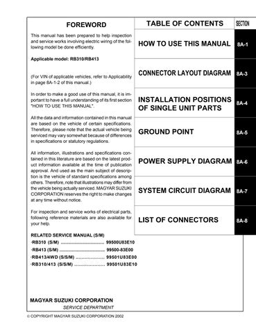
FOREWORD This manual has been prepared to help inspection and service works involving electric wiring of the following model be done efficiently.
TABLE OF CONTENTS
SECTION
HOW TO USE THIS MANUAL
8A-1
CONNECTOR LAYOUT DIAGRAM
8A-3
Applicable model: RB310/RB413
(For VIN of applicable vehicles, refer to Applicability in page 8A-1-2 of this manual.) In order to make a good use of this manual, it is important to have a full understanding of its first section "HOW TO USE THIS MANUAL". All the data and information contained in this manual are based on the vehicle of certain specifications. Therefore, please note that the actual vehicle being serviced may vary somewhat because of differences in specifications or statutory regulations. All information, illustrations and specifications contained in this literature are based on the latest product information available at the time of publication approval. And used as the main subject of description is the vehicle of standard specifications among others. Therefore, note that illustrations may differ from the vehicle being actually serviced. MAGYAR SUZUKI CORPORATION reserves the right to make changes at any time without notice. For inspection and service works of electrical parts, following reference materials are also available for your help. RELATED SERVICE MANUAL (S/M) ·RB310 (S/M) ................................... 99500U83E10 ·RB413 (S/M) ..................................... 99500-83E00 ·RB413/4WD (S/S/M) ................... 99501U83E00 ·RB310/413 (S/S/M) .................... 99501U83E10
MAGYAR SUZUKI CORPORATION SERVICE DEPARTMENT COPYRIGHT MAGYAR SUZUKI CORPORATION 2002
INSTALLATION POSITIONS 8A-4 OF SINGLE UNIT PARTS GROUND POINT
8A-5
POWER SUPPLY DIAGRAM 8A-6
SYSTEM CIRCUIT DIAGRAM
8A-7
LIST OF CONNECTORS
8A-8