1 minute read
Troubles and countermeasures


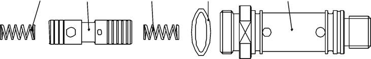
[3] (Diagram 6) •Remove the spring (1). •Remove the plunger assembly (15).(The orifice (2) and ring (8) cannot be disassembled.) •Remove the springs (1). •Remove the O-ring (12).
During assembly, pay attention to the assembly direction of the plunger assembly (15). (Install in such a way that the ring (8) can be seen when the assembly is viewed from the A port side.)
Diagram 6
Trouble state Primary cause Countermeasure
Oil leaking to the outside
A → B control flow is unstable. ・ Damage to the surfaces of the O-ring seals of each port section. ・ O-ring damage. ・ Spring (1) wear or breaking. ・ Foreign matter caught in the plunger assembly (15). ・ Foreign matter clogging the orifice (2). ・ Repair each port or perform replacement. ・ Replacement. ・ Spring (1) replacement. ・ Disassembly, cleaning, and repair or replacement. ・ Disassembly and cleaning.
Entire B → A flow is not flowing. ・ Foreign matter caught in the plunger assembly (15). ・ Disassembly, cleaning, and repair or replacement.