10 minute read
6. Maintenance Procedures


6.Maintenance Procedures (1)Required tools and tightening torque
Tool Dimension (mm) Code Part name Screw size Tightening torque (N•m)
Hexagon wrench 6 125 Hexagon socket head bolt M8 20.6±1.5
Wrench 22 312 Adjusting nut M14 68.6±4.9
32 302 Disk M14 Special jig (See Item 9.) 24 301 Joint M14 47.1±2.9 Other •Vapor corrosion inhibitor •White kerosene •Heat-resistant grease •Sandpaper (#1000, #2000) •Whetstone •Vise (2)Maintenance standards
Note: 1)It is desirable for seal materials such as O-rings to be replaced with each disassembly, but it is acceptable to reuse them after it is confirmed that they are not damaged. Note: 2)If the hexagon socket head bolt (125) is loosened, always replace the seal washer (121).
Maintenance inspection item
Leak amount Standard Remarks
When handle is in neutral1000 cc/min or more During operation2000 cc/min or more If either condition occurs, replace the remote control valve as one unit. Conditions Primary pressure 2.94 MPa Oil viscosity 23 mm2/s
Spool When wear on the sliding sections exceeds wear on the non-sliding sections by 10 μm or more, replace the remote control valve as one unit. The same approximate conditions as those listed above for leak amount are expected when the condition on the left occurs.
If the end section is worn by 1 mm or more, perform replacement.
Push rod
Operation section backlash
Operation stability Replace the operation section disk (302) and joint section (301) if there is backlash of 2 mm or more due to wear.
If abnormal noise, hunting, or a drop in primary pressure occurs during operation and the problem cannot be resolved with "7.Causes of Trouble and Countermeasures", replace the remote control valve as one unit. Make adjustments if the backlash is due to looseness in the tightening sections.
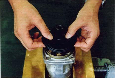
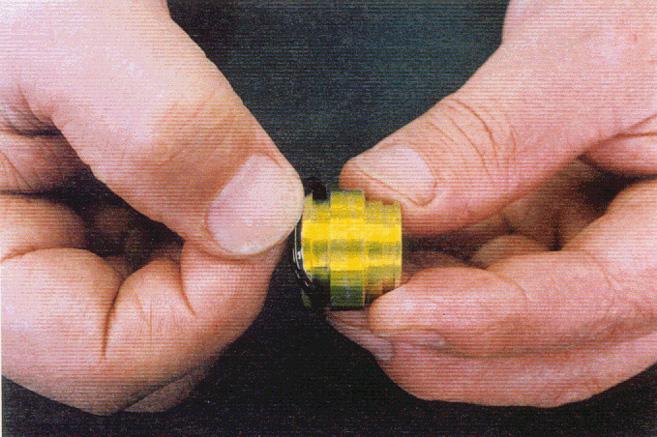
(3)Disassembly procedures [1]Preparations 1)Prepare a sufficiently spacious, solid and stable work platform so that parts will not fall or move during work. 2)Prepare the tools and materials indicated above. [2]General work precautions 1)Each part has been manufactured with a high degree of precision, so be careful not to let parts bump each other or fall when handling them. 2)If parts are struck or pulled with excessive force during work because they are tight, this may cause burrs or damage which leads to faulty assembly causing reduction in performance or oil leaks. Perform work carefully and thoroughly. 3)Rust may form on parts due to moisture or debris if the valve is left disassembled or if work is abandoned in the middle of disassembly. If work must be halted, be careful about preventing rust from forming and dust settling on parts. [3]Disassembly procedure 1)Clean the remote control valve with white kerosene. 2)Use copper plate (or lead plate) to secure the remote control valve in a vise. 3)Remove the bellows (501). <Notes> Place plugs in each port. Be careful not to tear the bellows (501).
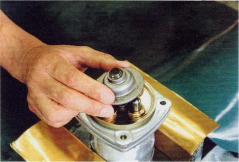
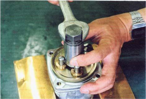
4)Use a wrench on the bolt width of the adjusting nut (312) and disk (302) to loosen them, and remove the adjusting nut and disk.
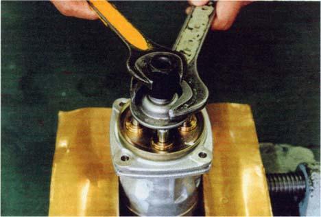

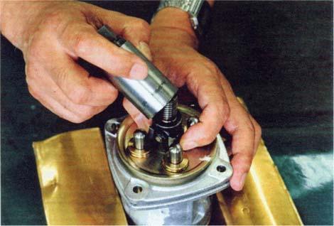
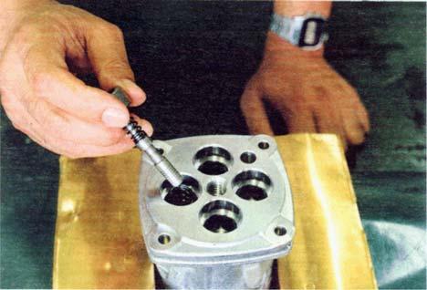
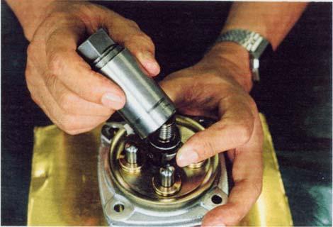
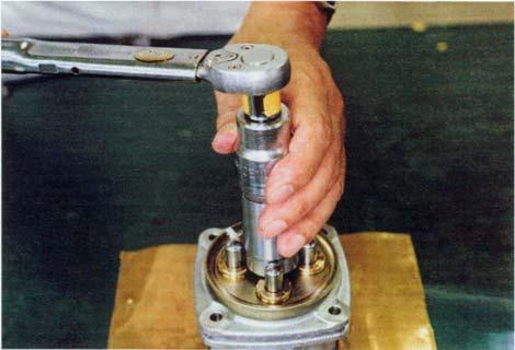
5)Use a jig to rotate the joint (301) to the left and loosen it.
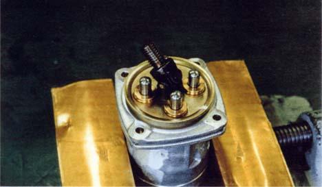
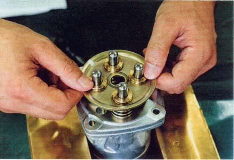
<Notes> •If a return spring (221) is strong, the plate (151), plugs (211), and push rods (212) will rise at the same time the joint (301) is loosened, so be careful of parts flying off when removing the joint. 6)Remove the plate (151).
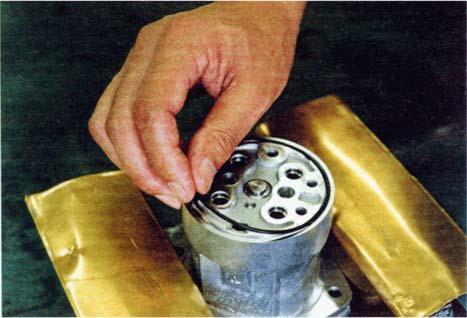
7)If a return spring (221) is weak, the plugs (211) will remain in the casing (101) due to the sliding resistance of the O-rings, so use a flathead screwdriver to remove them.
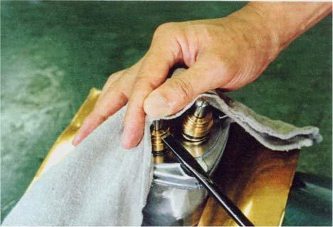
<Notes>
Use the groove in the outer circumference of the plugs (211) and remove them while making sure they are not damaged by an unbalanced load. •Use caution as plugs (211) may fly off when they are being removed due to the return springs (221).
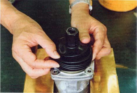
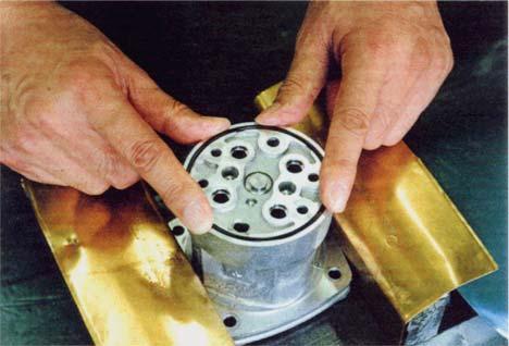
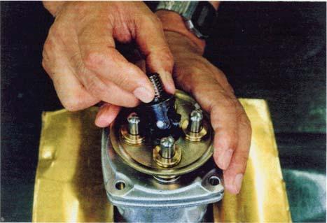
This shows the valve with the jig installed.
When the return spring (221) is strong When the return spring (221) is weak
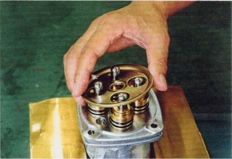
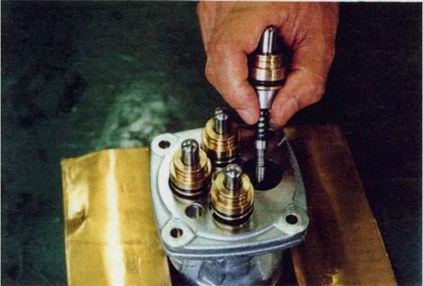
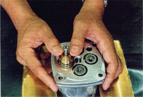
8)Remove the push rods (212), plugs (211), pressure reducing valve assemblies and the return springs (221) from the casing (101). <Notes> •Record the relation of parts to the casing hole positions.
9)Secure the remote control valve in a vise so that the port plate (111) is up. 10)Loosen and remove the hexagon socket head bolts (125) with a hexagon wrench.
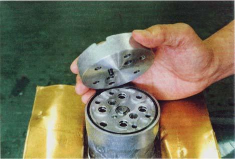
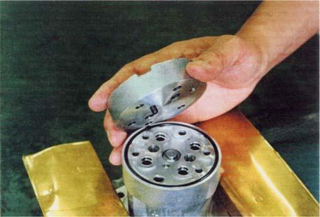
11)Remove the port plate (111) and O-ring (122) from the casing (101).
Pull out the bushing (131) from the casing (101).

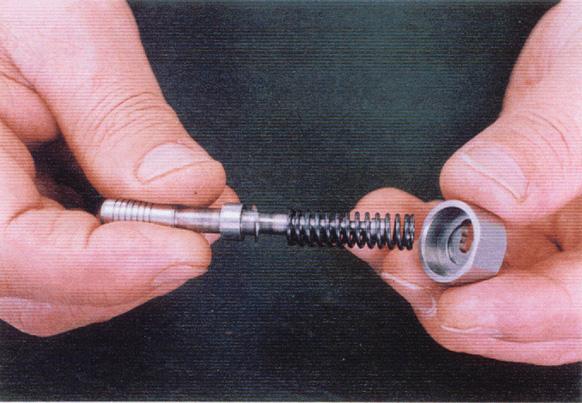
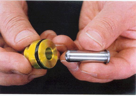
12)For disassembly of pressure reducing valve, press in the spring seating (216), move the spring seating (216) to the side while bending the secondary pressure spring (241), and remove the spring from the spools (201) by passing through the larger hole. Next, separate the spool (201), spring seating (216), secondary pressure spring (241), and washer 2 (217).
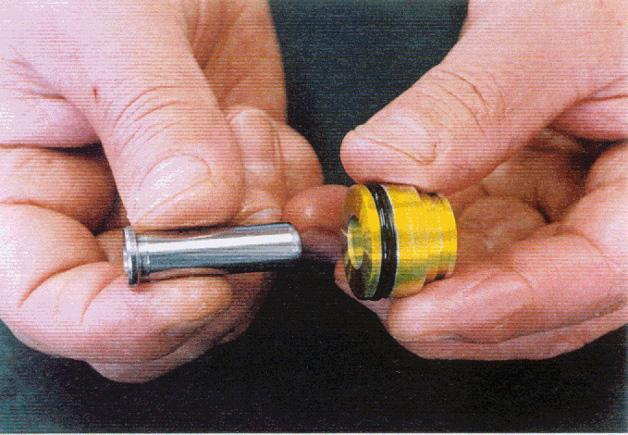
<Notes> Be careful not to scratch the surface of the spool (201). Do not lower the spring seating (216) by 6 mm or more. Handle these parts as assemblies until assembly. 13)Remove push rod (212) from the plug (211).


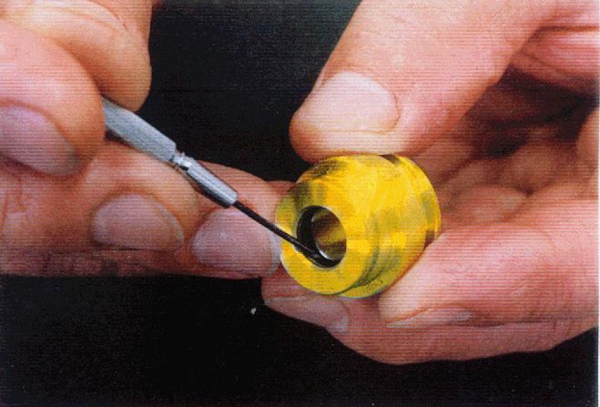
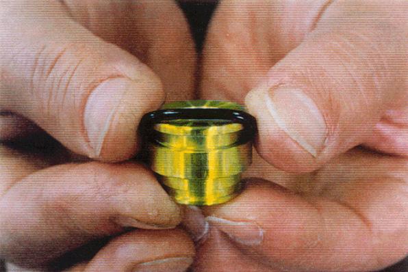
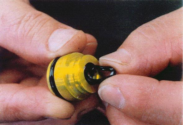
14)Remove O-ring (214) and seal (213) from the plug (211).
Use a small flathead screwdriver, etc. to remove seal (213).
15)Cleaning parts 1.Clean all parts by placing them in a rough cleaning container filled with white kerosene. (rough cleaning) 2.Clean all parts by placing them in a finish cleaning container filled with white kerosene, and thoroughly clean them up to the interior while slowly rotating them. (finish cleaning) Use a rag to thoroughly remove any white kerosene stuck to parts. <Notes> Scratching can easily occur if parts cleaning is begun just after parts are immersed in white kerosene, so let parts sit in white kerosene until debris and grease float to the surface. If the white kerosene is dirty, this will encourage damage to parts and result in reduced performance after reassembly. Thoroughly manage the level of cleanliness of the white kerosene. Do not dry parts with compressed air, as this will damage parts and cause rust to form due to debris and moisture being dispersed into the atmosphere. 16)Preventing rust on parts
Apply an anti-rust agent to each part. <Notes> Rust will form on parts if they are left as is after cleaning and this will cause reduced performance of functions after reassembly.
(4)Assembly procedures [1]Preparations 1)As with disassembly, prepare a work platform, tools and materials the same as in the 6. (3) Disassembly procedures. [2]General work precautions 1)Observe the same general work precautions as with disassembly. 2)When performing assembly, remove metal fragments and foreign matter from all parts and check that there are no burrs or nicks on parts. If there are burrs or nicks, use a whetstone to remove them. 3)As a rule, replace all O-rings and backup rings with new parts. 4)When installing O-rings and backup rings, be careful not to damage them. (Apply a thin layer of grease to ensure smooth installation.) 5)When installing parts, using grease is good for preventing parts from falling. 6)For bolts, etc., see Required tools and tightening torque table in 6. (1). 7)After assembly is complete, place plugs in all of the ports to prevent entry of debris. [3]Assembly procedure 1)Install bushings (131) and O-rings (122) on the casing (101).
2)Install the port plate (111) on the casing (101) with the hexagon socket head bolts (125) and seal washers121).
<Notes>
Be careful to install at a position that allows the spring pins (126) to enter the casing holes.
Replace the seal washers (121) with new parts.
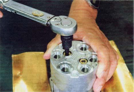
3)Tighten the hexagon socket head bolts (125) to the specified torque. <Notes> Slowly tighten 2 alternating.
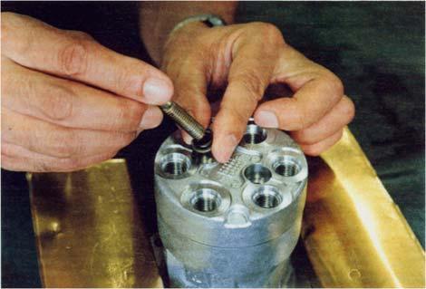
4)Insert the washer 2 (217), secondary pressure spring (241) and spring seating (216) onto the spool (201) in that order. Then, press in the spring seating (216) and move them to the side while bending the secondary pressure spring (241) to pass through the larger holes and install to the spool (201).
<Notes> Do not lower the spring seating by 6 mm or more. 5)Install the return springs (221) in the casing (101). Install the pressure reducing valve assemblies in the casing (101). <Notes> Install them in the positions they were in before disassembly.
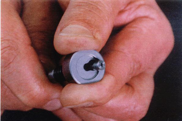
6)Install O-ring (214) on the plug (221).
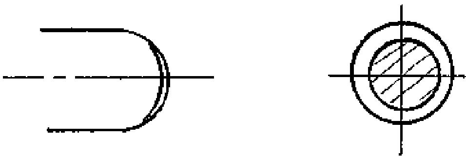
7)Install seal (213) on the plug (211). <Notes> Install so that the seal (213) lip is as shown in the following diagram.
8)Install push rod (212) (c) into the plug (211) (b).
<Notes>
Apply hydraulic oil (d) to surface of the push rod (c).
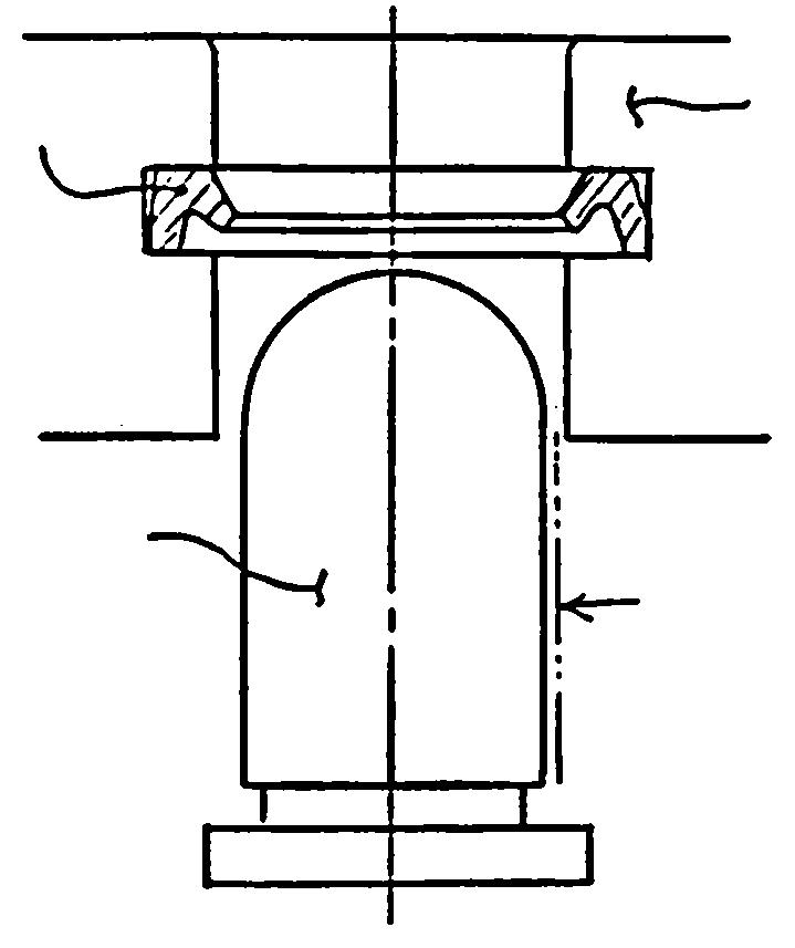
a Seal
9)Install the plug assemblies into the casing (101).
If the return spring (221) is weak, it will be stopped by the sliding resistance of the
O-ring (214). <Notes> Be careful not to scratch the casing hole (101) by forcing in the spool (201). If the return spring (221) is strong, use the plate (151) to install all 4 plug assemblies at the same time and temporarily tighten them with the joint (301). <Notes> Be careful of the plug assemblies and plate (151) flying off.
10)Install the plate (151). 11)Use a jig, and tighten the joint (301) to the casing (101) to the specified torque.
The diagram on the right shows the valve with the jig installed.
12)Install the disk (302) onto the joint (301). <Notes> Screw the disk in until it is equally touching each of the 4 push rods (212). Secondary pressure will cause faulty operation of the actual machine if the disk (302) is screwed in too much, so pay attention to adjustment of the tightening position.
13)Install the adjusting nut (312), use a wrench on the bolt width of the disk (302) to secure it, and tighten the adjusting nut to the specified torque. <Notes> During tightening, do not move the disk (302) position.
14)Apply grease to the rotating section of the joint (301) and to the top of the push rods (212).
15)Install the bellows (501). <Notes> Be careful not to tear the bellows (501).
16)Inject vapor corrosion inhibitor from each port plug and then place plugs in the ports.