3 minute read
5. Operation


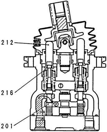
(2)Main part functions The function of the spool (201) is to switch the oil path either to have the hydraulic pressure fed from the hydraulic pump received by the P port and lead the P port pressurized oil to the output ports (1, 2, 3, 4) or to lead the output port pressurized oil to the T port. The output pressure operating on this spool (201) is determined by the secondary pressure setting spring (241). In order to change the deflection quantity of the secondary setting spring (241), the push rod (212) is inserted into the plug (211) in such a way that it can slide. The return spring (221) operates on the casing (101) and spring seating (216) and operates to return the push rod (212) in the displacement zero direction regardless of the output pressure and makes the spool (201) neutral return reliable. It also has the effect of a counter-force spring for giving an operator an appropriate operation feel. 5.Operation
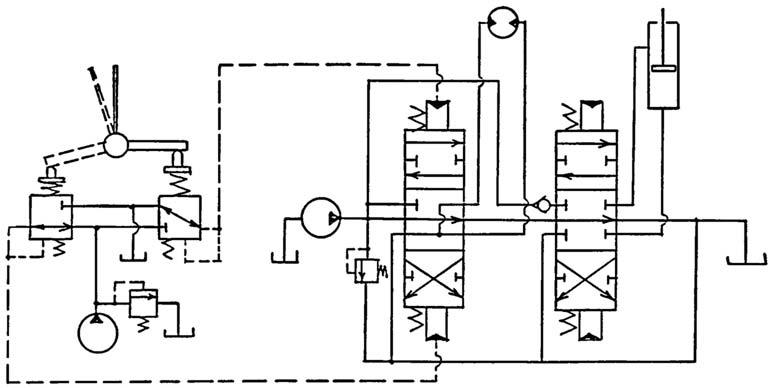
Operation of the remote control valve is explained based on the hydraulic circuit diagram (Diagram 1) and operation explanation diagrams (Diagram 2 - Diagram 4). Diagram 1 is a typical usage example for the remote control valve.
Diagram 1 Remote control valve usage example
1 Remote control valve 2 Pilot pump 3 Main pump 4 Control valve 5 Hydraulic motor 6 Hydraulic cylinder
(1)When the handle is in neutral (See Diagram 2.)
The secondary pressure setting spring (241) that determines the remote control valve output pressure does not act on the spool (201).
Therefore, the spool (201) is pressed up by the return spring (221) (spring seating 1 (216)) and the pressure flows through the output ports (2 and 4) and the T port, so the output pressure becomes the same as the tank pressure.

(2)When the handle is tilted (See Diagram 3.)
When the handle is tilted and the push rod (212) is moved through a stroke, the spring seating 1 (216) and spool (201) move down and the oil fed from the pilot pump flows out to the ports (2 and 4) through the P port and the ports (2 and 4) and pressure is generated.
(3)When the handle is held (See Diagram 4.)
When the handle is tilted and the pressure of the ports (2 and 4) rises to a pressure equivalent to the set spring force (241), the hydraulic pressure and the spring force are in balance.
When the port (2 and 4) pressure becomes higher than the set pressure, the ports (2 and 4) and the P port close and the ports (2 and 4) and the T port open. When the port (2 and 4) pressure becomes lower than the set pressure, the ports (2 and 4) and the P port open and the ports (2 and 4) and the T port close, so the secondary pressure is held constant.
Diagram 3 When the handle is tilted

Diagram 4 When handle held (secondary pressure at or above set pressure) (4)Operation in area in which the handle tilt is large (depends on the model)
For certain models, when the handle is flipped down beyond a certain angle, the spool top end section touches the push rod bore bottom section and the output pressure goes into the state of still being connected with the P port pressure.
Furthermore, with the structure in which the spring seating and spring are installed inside the push rod, when the handle is flipped down beyond a certain angle, the push rod bore bottom section and the spring touch. That spring force changes the 2nd pressure gradient and after that the push rod bore bottom section and the spring seating top end section touch, and the output pressure remains contacting the P port.