1 minute read
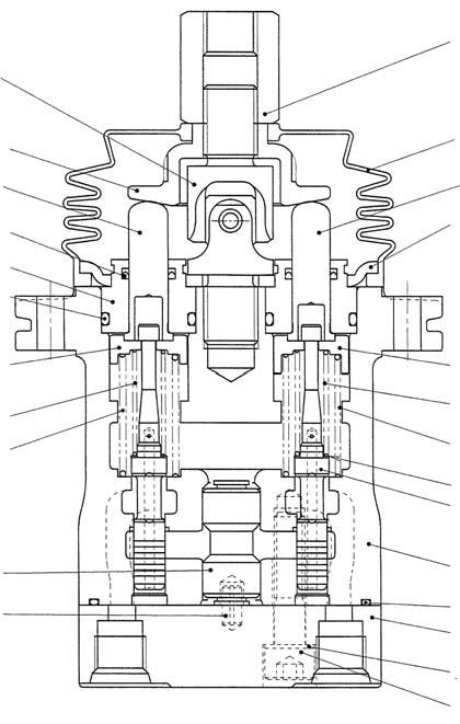
8. Remote Control Valve Assembly Cross-Section Diagram


8.Remote Control Valve Assembly Cross-Section Diagram
Tightening torque list Code Screw size Tightening torque 125 M8 20.6 ± 1.5 N•m 301 M14 47.1 ± 2.9 N•m 312 M14 68.6 ± 4.9 N•m
Hydraulic circuit
Code Part name
101 Casing 111 Port plate 121 Seal washer 122 O-ring 125 Hexagon socket head bolt 126 Spring pin 131 Bushing 151 Plate 201 Spool 211 Plug 212-1Push rod 212-2Push rod 213 Seal Q'ty 1 1 2 1 2 1 1 1 4 4 2 2 4 Code Part name
214 O-ring 216-1Spring seating 1 216-2Spring seating 1 217 Washer 2 221-1Spring 221-2Spring 221-3Spring 241-1Spring 241-2Spring 301 Joint 302 Disk 312 Adjusting nut 501 Bellows Q'ty 4 2 2 4 1 1 2 2 2 1 1 1 1
a Grease application to rotating sliding sections b Grease application to top c Secondary pressure adjustment shim Design central value t = 0.4, 1 shim d Do not reuse