17 minute read
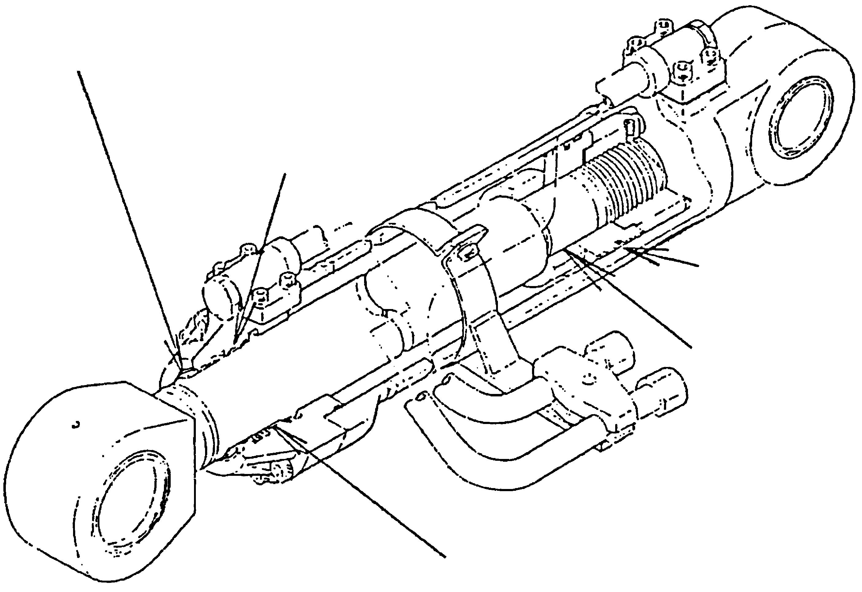
2. Handling of Specialty Jigs for Cylinder Repair


2.Handling of Specialty Jigs for Cylinder Repair
a Arm cylinder b Boom cylinder c Bucket cylinder d Seal ring insertion and calibration jig and tool e Cylinder head insertion guide jig and tool f Bushing removal jig and tool g Wiper ring press fitting jig and tool h Bushing press-fit jig and tool
(1) Configuration and characteristics of specialty jig and tool for cylinder repair 1)Seal ring insertion and calibration jig and tool [1] Configuration of jig and tool
(Remarks) The part numbers listed above are for a tube diameter of φ120. [2] Characteristics Inserting the seal ring without using a specialty jig will take a considerable amount of time and labor because the seal ring is hard. Using the specialty jig allows for anyone to insert the seal ring into the piston quickly, easily, and securely without causing any damage to the seal ring. 2)Bushing removal jig and tool [1] Configuration of jig and tool
(Remarks) The part numbers listed above are for rod diameter of φ80. [2] Characteristics
The bushing is roughly in the middle of the cylinder head due to being press fit by the hydraulic press, so removing the bushing during disassembly takes a considerable amount of time and labor.
However, using this specialty jig and tool allows for anyone to remove the bushing from the cylinder head quickly, easily and securely without causing any damage to the inside of the cylinder head.
Part No. Part name
KHV0530 Seal ring insertion and calibration jig and tool set Q'ty
1 Remarks
Inner guide Outer guide Plate (1) (1) (1)
Correction (1)
Part No. Part name Q'ty Remarks KHV0514 Bushing removal jig and tool set 1 Also used as the bushing press-fit jig and tool
Chuck assembly
Retainer (1) (1) Also used as the wiper ring press-fit jig and tool
Block 1 Prepare at each service plant.
Lever 1 Prepare at each service plant.
Hexagon wrench 1 Prepare at each service plant.
3)Cylinder head insertion guide jig and tool [1] Configuration of jig and tool
(Remarks) The part numbers listed above are for rod diameter of φ80. [2] Characteristics
However, using this specialty jig allows for anyone to slide the cylinder head assembly into the piston rod quickly, easily and securely without causing any damage to the various seals.
Part No. Part name Q'ty Remarks
KHV0550 Cylinder head insertion guide jig and tool 1
(2) Jig and tool table 1)For seal ring insertion and calibration
2)For bushing and wiper ring removal and press fitting
3) For cylinder head insertion
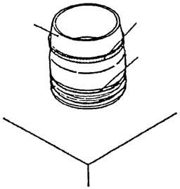
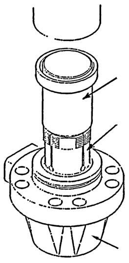
(3) Handling of jig and tool 1)Seal ring insertion and calibration procedures [1] Installation of O-ring (a) Stretch the O-ring (a) by hand and install it in the groove section of the piston (b).
Securely install the O-ring (a) so that it has no twists in it. If there are twists in the O-ring (a), this can cause an oil leak.
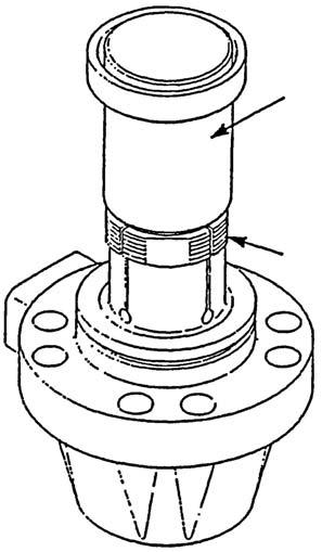
[2] Mounting of inner guide jig (c)
Mount the inner guide jig (c) from the upper side of the piston.
Install the thin end section (g) of the inner guide jig (c) into the upper side of the piston (b) with extreme care.
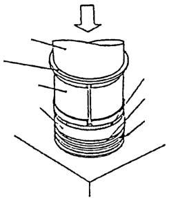
[3] Installation of seal ring (d)
Lightly coat the perimeter of the inner guide jig (c) with oil and set the seal ring (d) horizontal with the inner guide jig (c).
Be careful that no foreign matter such as dirt, shavings, or threads adheres to the outer circumference of the inner guide jig (c).
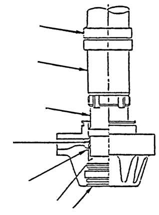
[4] Mounting of outer guide jig (f)
Place the plate (e) on the outer guide jig (f) and push it down by hand until the seal ring (d) touches the outer guide jig (f).
Be careful that the seal ring (d) set on the inner guide jig (c) is not set diagonally.
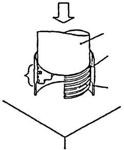
[5] Press-fitting
Press fit using the press until the seal ring (d) can be mounted in the groove section of the piston (b).
Be careful as mounting correctly in the groove may not be possible if the seal ring (d) is diagonal in relation to the inner guide jig (c).
Perform mounting quickly. [6] Removal of jig
After confirming that the seal ring (d) is installed completely into the groove section of the piston (b), remove the jigs according to the following sequence. 1) Remove the press rod (h). 2) Remove the plate (g). 3) Remove the outer guide jig (f). 4) Remove the inner guide jig (c).
This completes the seal ring (d) installation process.
Next, use the calibration jig (j) to perform installation calibration of the seal ring.
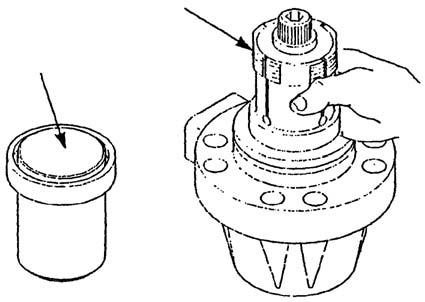
[7] Calibration jig preparation
Set the calibration jig (j) below the press.
Lightly coat the tapered section of the calibration jig (j) with oil and place the tapered section side up. Be careful that no foreign matter such as dirt, shavings, or threads adheres to the jig.
[8] Insertion of piston (b)
Slowly insert the piston (b) with the seal ring (d) installed into the calibration jig (j).
Insert so that the piston is horizontal inside the calibration jig (j).
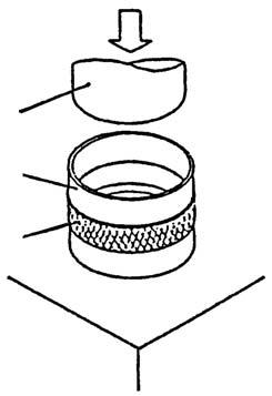
i Seal ring (internal O-ring) k Knurling
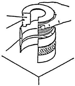
[9] Press-fitting
[10]Removal of calibration jig (j)
After seal ring calibration is complete, remove the jig according to the following sequence. 1) Remove the press rod (h). 2) Remove the calibration jig (j).
This completes the seal ring installation and calibration process.
Other cautions [1] These specialty jigs vary according to the specified cylinder bore.Select the corresponding jig and tool from the list on the separate sheet to perform work. [2] The lower section of the inner guide jig (c) is extremely thin, so use sufficient caution when handling and storing.
[3] Before installation, clean the seal, piston (b) and jig using compressed air or another appropriate method.
If cleaning is not thorough, foreign matter such as dirt may cause defects such as oil leak.
i Seal ring (internal O-ring)
g Thin end section
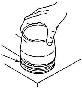
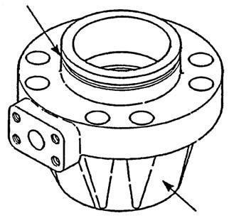
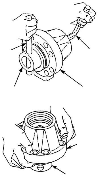
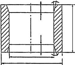
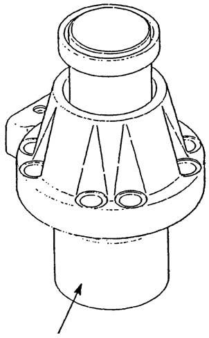
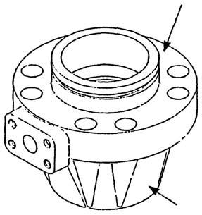
2)Bushing removal procedures [1] Setting of cylinder head Set the cylinder head (b) on top of the work platform with the cylinder tube connection surface (a) facing up.
Clean the top of the work platform and be careful that the line joint section will not get scratched due to foreign matter such as dirt or shavings.
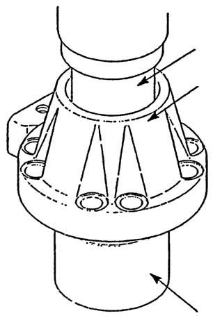
[2] Removal of snap ring (c)
Remove the snap ring (c) for the bushing stopper installed in the cylinder head.
Secure the cylinder head (b) with a vise, and install the snap ring (c) so that it is elevated using the tip of a special tool.
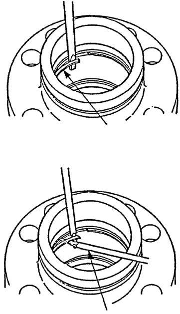
d Screwdriver
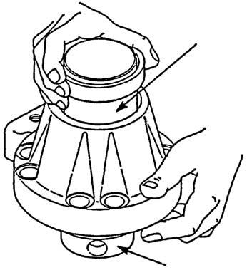
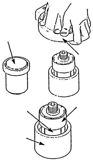
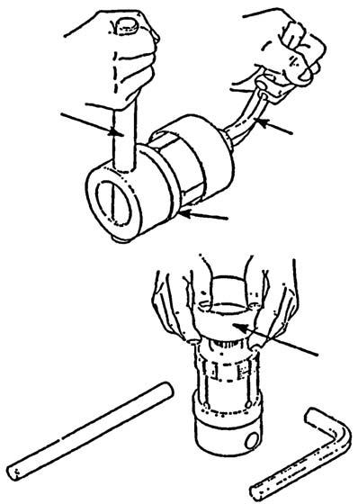
[3] Setting of chuck assembly jig (f)
Insert the chuck assembly jig (f) little by little into the cylinder head (b) until the tip of the blade of the chuck assembly (f) reaches the end of the head bushing (h). 1) While being careful not to scratch the inner circumference of the cylinder head (b) with the blade section (e), insert the chuck assembly (f) little by little into the cylinder head (b). 2) Be careful that the blade section (e) does not fly out from the head bushing end section (h).
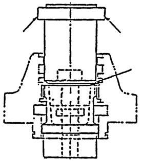
[4] Temporary tightening 1) Fit the hexagon wrench (j) in the adjuster head section on the chuck assembly jig (f) end, and insert the lever (i) into the circular hole of the chuck assembly jig (f) rear section at the same time. 2) Insert so that the hexagon wrench (j) and lever (i) can be pressed back and forth and tighten to a degree where the jig will not fall if the cylinder head (b) is lifted.
A tightening torque of 49.3 N•m or lower is sufficient.
With the cylinder head (b) left mounted on the chuck assembly jig (f), firmly grip both sides of the cylinder head (b) with both hands and move it to the press work platform while being careful that it does not fall.
g Head bushing contact surface
[5] Mounting of retainer jig (k)
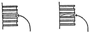
Gently place the retainer jig (k) so that it covers the stepped section of the wedge inside the chuck assembly jig (f). 1) Point the large-diameter section (flange section) (l) of the retainer jig (k) upwards and place it as shown in the right diagram. 2) Clean the top of the press (n) work platform and be careful that the bottom surface section of the chuck assembly jig (f) will not get scratched due to foreign matter such as dirt or shavings and that it will not tilt.
[6] Retightening
Press the top part of the retainer jig (k) little by little so that the chuck assembly jig (f) blade section meshes with the bushing surface.
Make the press (n) load 2 - 3 t.
Make sure to press using the retainer jig (k).
m Wedge
[7] Block jig (o) preparation
Prepare the block jig (o) and place the cylinder head (b) on top of it while aligning it with the center axis.
Select the appropriate block shape and dimensions from the table below.
[8] For bushing removal 1) Move the block jig (o) and cylinder head assembly (with the retainer jig (k) and chuck assembly jig (f)) directly under the press. 2) Press the top surface of the retainer jig (k) little by little until the bushing comes out from the cylinder head (b) (until the sound of the bottom surface of the chuck assembly jig (f) falling to the work platform is heard).
Normally, removal can be done at a load of less than 3 t.
The stroke of the press ram (p) differs depending on the size of the cylinder head (b), but it is about 32 - 52 mm. 1) Make sure to press using the retainer jig (k). 2) If the center axis of the block jig (o) and the cylinder head assembly do not match, halt the press operation and move the block jig (o). Start work again after aligning the center axis.
[9] Removal of chuck assembly jig (f) with bushing 1) After pulling both the cylinder head assembly (with the retainer jig (k) and chuck assembly jig (f)) and block jig (o) out from directly under the press, pull the retainer jig (k) out of the cylinder head (b), lift the cylinder head (b) with both hands, and move it to a separate location. 2) Pull out the chuck assembly jig (f) with bushing from inside the block jig (o), and move it to the work platform.
To prevent danger, never work directly under the press.
[10]Removal of bushing 1) Place the chuck assembly jig (f) with bushing sideways on the work platform and fit the hexagon wrench (j) on the adjuster head section on the end of the chuck assembly jig (f), and insert the lever (i) into the circular hole of the chuck assembly jig (f) rear section at the same time. 2) Insert so that the hexagon wrench (j) and lever (i) can be pressed back and forth and loosen the adjuster. 3) Move the chuck assembly jig (f) to a vertical position and rotate the adjuster with the fingers until the wedge (m) is elevated by about 5 mm. 4) After confirming that the bushing (q) is separated form the chuck blade section, gently remove the bushing from the chuck assembly jig (f).
Clean the top of the work platform and be careful that the bottom surface section or outer circumference surface of the chuck assembly jig (f) will not get scratched due to foreign matter such as dirt or shavings and that it will not tilt.
[11]Return tightening of adjuster (s)
Tighten the chuck assembly jig (f) with the bushing removed until there is no gap between the adjuster (s) and top surface of the wedge (m) while rotating the adjuster (s) with the fingers.
Do not remove the adjuster (s) and wedge (m) from the chuck assembly jig (f) and store them in a state similar to their original state.
Other cautions [1] This specialty jig will vary depending on the specified piston rod diameter, so select the corresponding jig from the list on the separate sheet to perform work. [2] The chuck blade section is an important part, so use sufficient caution when handling and storing. 3)Bushing press-fit procedures [1] Setting of cylinder head (b) Set the cylinder head (b) on top of the press work platform with the cylinder head tube connection surface (a) facing up. 1) Clean the top of the work platform and be careful that the bottom surface section of the cylinder head (b) will not get scratched due to foreign matter such as dirt or shavings and that it will not tilt. 2) Perform work after sufficiently removing foreign matter using air.
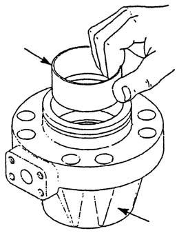
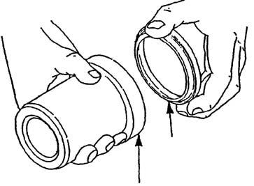
[2] Temporary placement of bushing (c)
Temporarily place the bushing (c) horizontally in the inner diameter section of the cylinder head (b).
Check that there is no adhered foreign matter on the inner and outer circumference of the bushing (c).
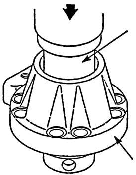
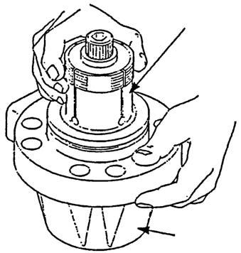
[3] Mounting of chuck assembly jig (d)
Mount the chuck assembly jig (d) little by little in the cylinder head (b) while supporting the jig with the fingers.
In the area (g) between the adjuster (i) and wedge (h) of the chuck assembly jig (d), check that tightening has been done to a degree to where there is no gap.
[4] Mounting of retainer jig (e)
Gently place the retainer jig (e) so that the end is aligned with the wedge stepped section (f) of the chuck assembly jig (d).
Point the large-diameter section (flange section) of the retainer jig (e) upwards and place it as shown in the left diagram.
[5] Press-fit preparation
Move the cylinder head, with the retainer jig (e) and chuck assembly jig (d) mounted on it, directly under the press.
Adjust so that the press (ram) (j) center axis is aligned with the center axes of the retainer jig (e) and chuck assembly jig (d).
[6] Bushing (c) press fitting
Press the bolt head section of the adjuster section with the press, and press fit the bushing (c) on to the specified position on the cylinder head (b) little by little.
Keep the press load at 5 t or lower.
Check that the bushing end surface is below the snap ring groove (k) and perform press fitting again if it is too shallow.

[7] Removal of retainer jig (e) and chuck assembly jig (d)
After press fitting of the bushing is complete, remove the retainer jig (e) and chuck assembly jig (d) from the cylinder head (b).Next, perform mounting of seals and press fitting of the wiper ring.
Check that the bushing (c) is correctly press fit.
Other cautions [1] This specialty jig will vary depending on the specified piston rod diameter, so select the corresponding jig from the list on the separate sheet to perform work. [2] The chuck blade section is an important part, so use sufficient caution when handling and storing. 4)Wiper ring press fitting procedures [1] Setting of cylinder head (a) Set the cylinder head (a) on top of the work platform with the cylinder head (a) tube connection surface facing up.
Clean the top of the work platform and be careful that the bottom surface section of the cylinder head (a) will not get scratched due to foreign matter such as dirt or shavings. [2] Insertion of wiper ring (b)
Insert the wiper ring (b) with the lip side facing the inside of the groove of the retainer jig (c).
Sufficiently check that there is no dirt or foreigner matter inside the wiper ring (b) insertion groove of the retainer jig (e). Perform work after sufficiently removing foreign matter using air.

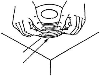
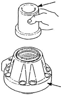
[3] Mounting of retainer jig (c)
Gently mount the retainer on the top of the cylinder head (a) with the wiper ring insertion side (d) facing down.
Gently place the retainer jig (c) on the cylinder head (a) while making sure it is horizontal on the work platform.
[4] Press-fit preparation
Move the cylinder head (a), with the retainer jig (c) mounted on it, directly under the press.
Adjust so that the press (ram) (e) center axis is aligned with the center axis of the retainer jig (c).
[5] Press fitting of wiper ring (b)
Press the head section of the retainer jig (c) with the press and press fit the wiper ring (b) on to the specified position on the cylinder head (a).
Keep the press load at 1 t or lower.
Press fit until the flange of the retainer jig (c) touches the end surface of the cylinder head.
[6] Removal of retainer jig (c)
After press fitting of the wiper ring (b) is complete, remove the retainer jig (c) from the cylinder head (a).
Check that the wiper ring (b) is correctly press fit.
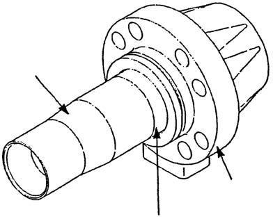
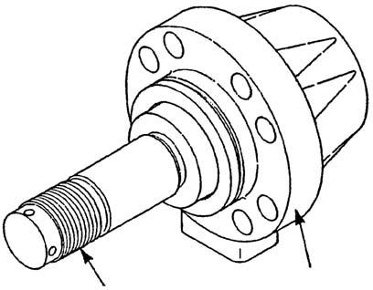
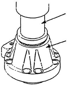
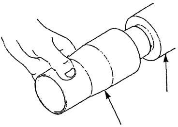
5)Cylinder head insertion procedures [1] Securing the piston rod (e)
Face the piston rod threaded section (a) in a direction convenient to work and secure it. Be very careful with handling to prevent scratching of the piston rod outer circumference (b).
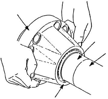
[2] Mounting of guide jig (d)
Point the large diameter side of the guide jig (d) in front and insert it onto the piston rod (e) up to the tip of the stepped section (c).
1)When inserting the guide jig (d) onto the piston rod (e), be careful to not scratch the threaded section of the piston rod (a). 2) Be careful that the threaded section (a) and outer circumference of the stepped section of the piston rod are not scratched due to foreign matter such as dirt or shavings.
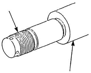
Piston rod (e) tip section

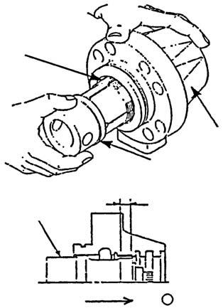
[3] Insertion of cylinder head assembly (f)
Put the wiper ring mounting side (g) of the cylinder head assembly (f) in front facing the head side of the piston rod and push the cylinder head assembly (f) onto the specified position of the piston rod (e) in such a way that the outer circumference surface of the guide jig (d) slides.
1)Support the cylinder head assembly (f) firmly with both hands and be careful that it does not fall on the feet. 2) Lightly coating the outer circumference surface of the guide jig (d) and piston rod (e) allows it to slide smoothly. [4] Removal of guide jig (d)
After checking that the cylinder head assembly (f) is completely inserted into the piston rod (e), remove the guide from the piston rod (e).Next, assembly the piston sections, etc. in the piston rod (e).
When removing the guide jig (d), be very careful not to scratch the threaded section of the piston rod (a).