1 minute read
2. Procedures for Assembly and Disassembly of Overload Relief Valve


2.Procedures for Assembly and Disassembly of Overload Relief Valve
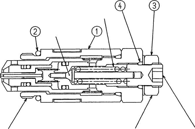
"*" on the side of codes give O-ring part numbers. a Poppet b Spring c Lock nut Hexagon diameter: 17 mm d Adjuster Hexagon diameter: 6 mm
[1]Disassembly
This part is replaced as an assembly.
When replacing, loosen the cap (1) (hexagon diameter: 24 mm) with a wrench and remove the
O-ring (2).Also, if oil leaks from the adjuster kit section (3), loosen the adjuster kit and replace the
O-ring (4).
[2]Assembly
Check carefully that there is no debris, paint fragments, or the like around the thread section of the cap (1) and assemble a new O-ring (2).
Also clean the valve housing relief valve installation section well, install the relief valve, and tighten the cap (1). (Tightening torque: 59 - 69 N•m)
When the adjuster kit has been disassembled, clean around the thread sections well and adjust the pressure according to "3.Relief Valve Adjustment」(page135).
Be careful disassembling the adjuster kit. The spring may make parts fly out and the poppet could be lost.
All the tightening torque values indicated above are for the wet state (with hydraulic oil).