8 minute read
4. Assembly Procedures


4.Assembly Procedures
Precautions before assembly [1]Clean each part with clean oil and blow dry them. [2]Use sufficient caution in handling each cleaned part to prevent adherence of debris and to prevent dents and scratches. [3]Replace the seal sections with new ones. [4]Tighten each tightening section to the specified torque. [5]Coat oil seals and O-rings with lithium grease in advance. [6]There are many small accessories, so be very careful not to lose them. (In particular, be careful about them falling into holes.)
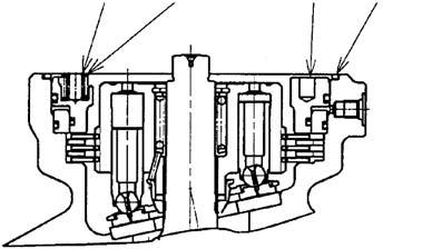
Assembly Perform assembly according to the following procedure. [1]Assembly of motor section 1)Install the collar (2-7), spring (2-8), and washer (2-9) on the cylinder block (2-6). Be careful to install the collar (2-7) in the correct direction.
2)Install the snap ring (2-10) while pushing the washer (2-9).
Check that the snap ring is securely held.
3)Coat the pin (2-11) with grease and install it on the cylinder block (2-6). 4)Install the retainer holder (2-13).
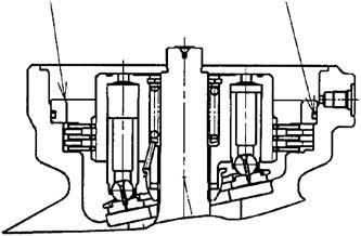
Cylinder block
a Tapered surface
5)Set the piston assembly (2-14) on the retainer plate (2-12) and install it on the cylinder block (2-6).
Attach after applying sufficient hydraulic oil to the sliding section.
Be careful to install the retainer plate in the correct direction.
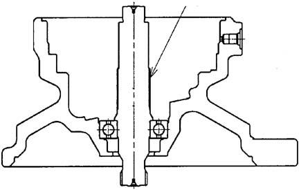
6)Press fit the ball bearing (2-3) to the shaft (2-4). (Reference jig No. 1)
7)Press fit the shaft (2-4) and the ball bearing (2-2) to the case (2-1).
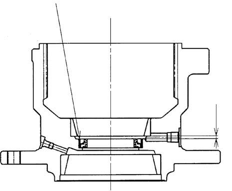
8)Coat the back surface of the thrust plate (25) with grease and install it.
The thrust plate has a specific direction.
b The side with the taper should face the motor case.
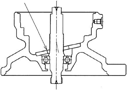
9)Coat the front surface of the thrust plate (25) with grease and install the cylinder block assembly.
Cylinder block assembly •Cylinder block (2-6) •Pin (2-11) •Retainer holder (2-13) •Retainer plate (2-12) •Piston assembly (2-14) 10)(*2: only parking brake specification machines)
Install the disks (2-15) and friction plates (2-16).
Be careful to install the disks and friction plates in the correct position.
Align the disks with the positions with no spline teeth and install them.
11)(*2 only machines with the parking brake)
Install the O-ring (2-18) coated with grease on the collar (2-17).
Make sure to press fit using the press.
If a plastic hammer is used, the cylinder block will bounce and the disk plates and friction plates will fall off.
12)(*2: only machines with the parking brake)
Coat the O-rings (2-20) and (2-21) with grease and install them on the brake piston (2-19). 13)(*2: only machines with the parking brake)
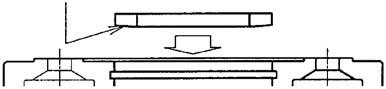
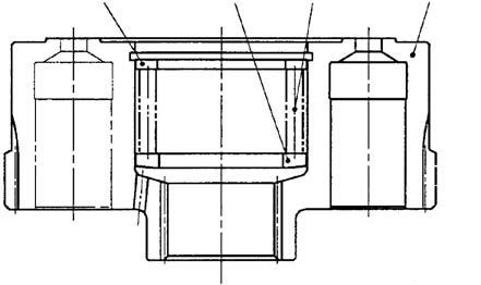
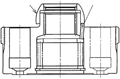
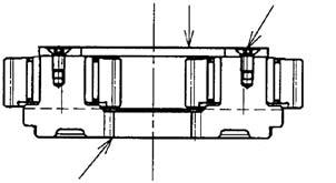
Install the brake piston (2-19) on the case (2-1).
Press fit the brake piston in the position shown in the right diagram. (This makes pin-joining with the cover impossible.)
Make sure to press fit using the press.
If a plastic hammer is used, the cylinder block will bounce and the disk plates will fall off.
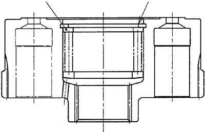
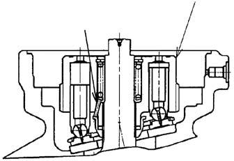
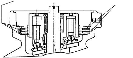
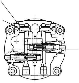
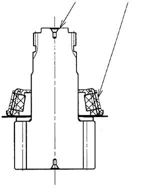
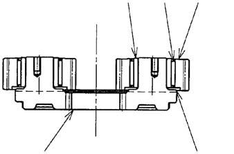
14)Coat the springs (2-22) (12 large springs), springs (2-23) (8 small springs), and O-ring (2-24) with grease and install them.
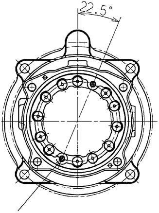
Install the springs (small) (2-23) in the positions shown below.
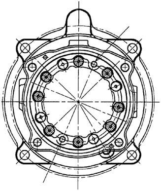
Spring (small) (2-23) installation positions
d Pin hole c Install so that the this position. φ8.5 pin hole is in
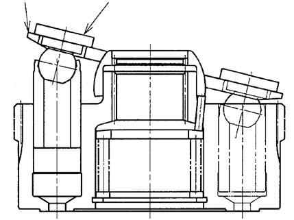
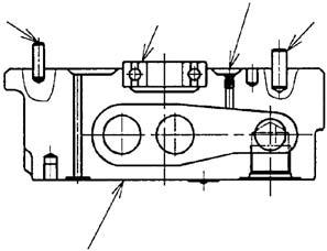
15)Install the O-rings (2-27-6-7, 15, 17) and backup rings (2-27-6-16, 18) coated with grease in the relief valve (2-27-6) and install on the cover (2-27-1).
Tightening torque: 37 ± 20 N•m (hexagon diameter: 27 mm)
The poppet seat (2-27-6-3) may be left in the cover at some times.
16)Install the check valve (2-27-2) and spring (2-27-5) on the cover (2-27-1).
17)Install the O-ring (2-27-4) coated with grease on the plug (2-27-3) and install it on the cover (2-27).
Tightening torque: 157 ± 10 N•m (hexagon socket diameter: 12 mm)
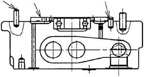
18)Press fit the ball bearing (2-28). (Reference jig No. 22)
Install the pins (2-31, 32) on the cover (227-1) and screw in the orifice (2-27-7).
After screwing in the orifice (2-27-7), perform caulking around the circumference.
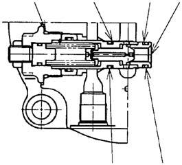
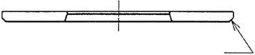
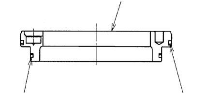
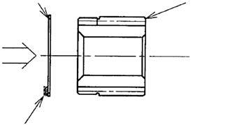
19)Install the pin (2-29) and then install the valve plate (2-30).
To prevent it from falling off, apply grease to the back surface.
After installing the pin (2-29), perform punch caulking at the position in the diagram below.
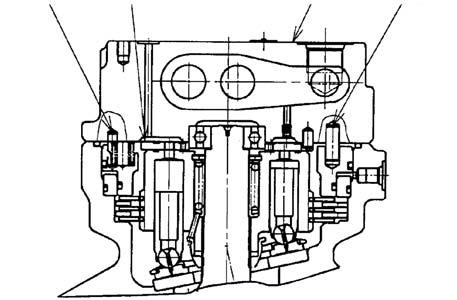
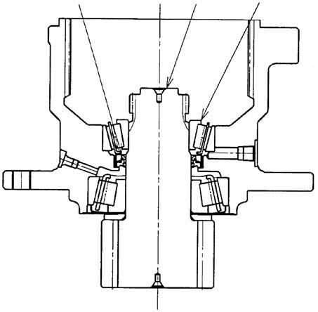
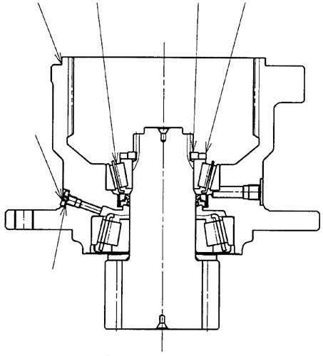
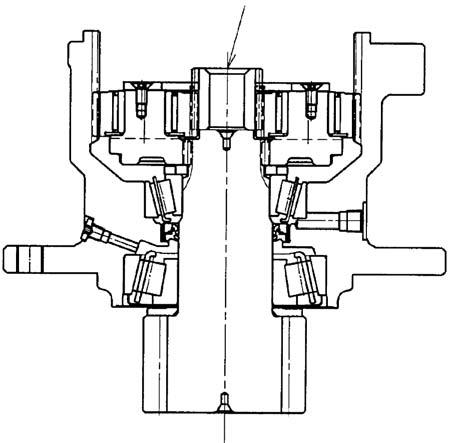
20)Install the cover assembly (2-27) on the case (2-1) while being careful about the positions of the pins (2-31) and (2-32).
Be careful of the pins and valve plate falling off.
See the note on brake piston assembly in 13) for the position of the pin (2-32).
21)After temporarily fastening the hexagon socket head bolts (2-33), tighten them to the specified torque.
Tightening torque: 177 ± 10 N•m (hexagon socket diameter: 12 mm)
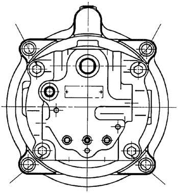
Pin (2-29) caulking position
e Punch caulking range f Punch caulking in 1 location g Center of motor side
[2]Assembly of reduction gear
The parts around the pinion shaft are replaced as part of the housing assembly (B6).
The following is indicated as reference. 1)Press fit the oil seal (1-7). (press fitting dimensions: 4.25 [shown in diagram]) Before press fitting, coat the oil seal installation section of the housing and the oil seal outer circumference with grease.(Reference jig No. 3)
2)Coat the inner race (1-6) of the tapered roller bearing installed on the pinion shaft (1-2) with grease.
Grease brand: Shell Alvania Grease 2
Grease fill quantity: 80 - 90 cm2 (about 66 75 g)
3)Install the pinion shaft (1-2), etc.
Install the inner race (1-8) of the tapered roller bearing.
Before installing the pinion shaft (1-2), etc., coat the lip section of the oil seal (1-7) with grease.
Before installing the pinion shaft, check that the plug (1-35) is not inserted.
If the pinion shaft is installed with the plug left inserted, internal air pressure will rise and the oil seal (1-7) will be damaged.
h Dimensions after oil seal press fitting
4)While applying a load of 11770 N to the inner race of the tapered roller bearing (18), install the collar (1-10).(Reference jig
No. 4) Install the O-ring (1-36) coated with grease on the plug (1-35), and install it on the housing (1-1).
Tightening torque: 15.7 ± 0.8 N•m (hexagon socket diameter: 5 mm)
5)Install the thrust washer (1-12), inner race (1-13), needle bearing (1-14), and planetary gear (1-15) on the holder (1-11).
6)Install the thrust plate (1-16) and screw (117) on the holder (1-11).
Coat the screw with Loctite #242 before tightening it.
Tightening torque: 24.5 ± 4.9 N•m (hexagon socket diameter)
7)Install the holder (1-11), etc.
8)Install the snap ring (1-26) on the sun gear (1-18).
9)Install the sun gear (1-18).

Snap ring installation direction
i Side with rounded section Snap ring installation direction
10)Install the holder (1-19).
11)Install the thrust washer (1-20), inner race (1-21), needle bearing (1-22), planetary gear (1-23), thrust plate (1-24), drive gear (1-25), and O-ring (1-37).
When replacing component parts from within the reduction gear, based on measurements of the dimensions below, select one of the thrust plates (1-24) from the thrust plate kit (B5) according to the selection table.
j Reference k Between inner race and housing
Thrust plate (1-24) selection table E dimensions (measured dimensions) 5.3 - lower than 5.8
Thrust plate (1-24) usage part No. (plate thickness) B0841-23031 (2.8 ± 0.14)
5.8 - lower than 6.5 6.5 - 7.0 B0841-23030 (2.3 ± 0.12) B0841-23029 (1.8 ± 0.10) F dimensions (measured dimensions) (7.96 - 8.74) (7.98 - 8.72) (8.2 - 8.9)

[3]Assembly of swing motor assembly 1)Check the direction of the reduction gear assembly and place it on the motor assembly. After temporarily tightening the hexagon socket head bolts (3), tighten them to the specified torque. Tightening torque: 177 ± 10 N•m (hexagon socket diameter: 12 mm)
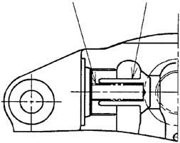
[4]Installation of reverse prevention valve (* only reverse prevention valve specification machines) 1)Install the O-rings (2-38) on the cover (227-1). 2)Place the valve assembly (2-34) on the cover (2-27-1) and tighten the hexagon socket head bolts (2-39). Tightening torque: 32.4 ± 2.0 N•m (hexagon socket diameter: 6 mm) (See the "Reverse Prevention Valve」 (page117) for the reverse prevention valve assembly and disassembly procedures.)