1 minute read
Assembly Diagram


8) Remove the 2 parallel pins [42] from the spindle [2].
9) Remove the 2 O-rings [43] and the O-ring [44] from the spindle [2].
Note •Do not reuse the removed O-rings [43] and [44].
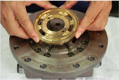
[9] Disassembly of parts mounted on rear flange 1) Place the rear flange [301] on the work platform so that the surface matching with the spindle [2] faces up. 2) Remove the rear flange [301] from the timing plate [109]. Note •Stiffness may occur during removal due to adherence of oil on the surface that matches with the rear flange. Inserting a scoop into the casting grooves of the rear flange side matching surface makes it possible to remove the timing plate by lightly lifting it. Do not use sharp tools such as a screwdriver for insertion into the matching surface, as these can cause scratches that can result in oil leaks. 3) Remove the parallel pin [342] from the rear flange [301].