1
2
3
5
4
7
6
RENR3445 July 2001
8
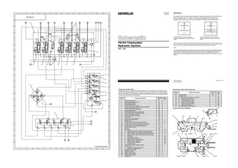
This publication shows the hydraulic system schematics for machines equipped with either of the films illustrated below for the joystick control. For full details of the joystick control arrangements refer to Operation and Maintenance Manual SEBU7017 or SEBU7111, or Operation and Maintenance Manual Joystick Control Supplement SEBU7100 (to be used in conjunction with SEBU7017 Operation and Maintenance Manual).
SCHEMATIC 2 A
A 22
8
23
40
11
17
12
18
33
19
33
19
Introduction
19
B
B 1234474
123-4474 Film (Boom Control). Installed on machines equipped with an early type of joystick control. 32
C
C
TH103 Telehandler Hydraulic System
Early type of joystick controls have a straight handle, with a pushbutton switch on the front and a rocker switch on the top. Later type of joystick controls have curved handles with pushbutton switches on the front and rear, and a rocker switch on top. The hydraulic valve section of the joystick control is the SAME on both types. Notes:
3PN1 - 2026
On early machines the spools in the implement section for boom raise/lower (24A) and the implement section for boom extend/retract section (25A) of bank valve (23) connects both work ports together and to tank when in the center position. On later machines the spools in the implement section for boom raise/lower (24) and the implement section for boom extend/retract (25) of bank valve (23) blocks the flow of oil to tank when in the center position.
31
D
141-8438 Film (Boom Control). Installed on machines equipped with a later type of joystick control.
D
40
24
26
25
41 27
29
28
41
30
E
E
44
BL JBL 45
BR
F
JBR 42
46
TL
47
JTL
1
Component Location Table
TR 48
JTR
G
4
2
50
PT
43
H
H
JS
43
51
I
P1
P2
37
Y
43
T A2
J
B2
A1
B1
X1
27
X2
J
39
K
K
ACCESS PLATFORM 1
2
3
4
5
6
Separate schematics in this publication are identified as Schematic 1 and Schematic 2. Components common to both schematics have the same item number. In Schematic 2, some item numbers are shown in boxes at the end of some of the hydraulic lines. This provides a reference to the component on Schematic 1 that connects to these lines. The schematics have borders with grids to locate the components. Identify both the cross reference and the number on the schematic from the following table. Component Item No.
T
I
G
49
3
Printed in U.S.A.
© 2001 Caterpillar All Rights Reserved
F
7
8
1 2 3 4 5 6 7 8 9 10 11 12 13 14 15 16 17 18 19 19A 20 21 22 23 24 24A 25 25A 26 27 28 29 30 31 32 33 34 35 36 37 38 39 39A 40 41
Component Description Front Steering Cylinder Selector Valve (steering mode) Rear Steering Cylinder Compensating Cylinder Work Tool Cylinder (if equipped) Load Control Valve for Work Tool Cylinder (if equipped) Boom Cylinder (boom raise/lower) Load control Valve for Boom Cylinder Compensating Cylinder Telescoping Cylinder (boom extend/retract) Load Control Valve for Telescoping Cylinder Valve (compensating cylinders) Load Control Valve for Tilt Cylinder Tilt Cylinder Work Tool Cylinder (if equipped) Couplers (quick disconnect) Diverter Valve Relief Valves (auxiliary services) (part of item 23) Control Valve for Frame Leveling (closed center spool) Control Valve for Frame Leveling (open center spool) Load Control Valve for Frame Leveling Cylinder Frame Leveling Cylinder Oil Filter Bank Valve Implement Section (boom raise/lower) (closed center spool) Implement Section (boom raise/lower) (open center spool) Implement Section (boom extend/retract) (closed center spool) Implement Section (boom extend/retract) (open center spool) Inlet Section Pressure Reducing Valve Implement Section (coupler tilt) Implement Section (auxiliary services) Implement Section (stabilizers) Implement Section (stabilizers) Signal Relief Valve Load Control Valves for Stabilizer Cylinders Control Valve Solenoid Valves (pilot control system) Solenoid valve (differential lock) Differential Lock Cylinder Stabilizer Cylinders Brake Cylinder (boost) Brake Cylinder (master) Metering Pump (steering) Piston Pump
Component Location Table (Continued) Component Item No. 42 43 44 45 46 47 48 49 50 51
Schematic Location No. 1 A1 A2 A2 A3 A8 A8 B3 C3 B5 B5 B5 B8 B8 B9 B11 B11 B11 C6 C10 E11 C11 C11 D2 E3 E3 C3 E4 C3 E5 E5 E6 E6 E7 E7 E8 E10 F5 F6 F8 F9 F10 F11 F11 F3 F3
No. 2 A6 A2 E2 E3 E3 E4 E4 E5 E5 D8 C8 -
Schematic Location
Component Description
No. 1 F11 H2 -
Joystick Control Hydraulic Tank Control Valve (Access Platform - if equipped) Solenoid Valve (boom lower) Solenoid Valve (boom raise) Solenoid Valve (boom retract) Solenoid Valve (boom extend) Solenoid Valve (boom speed) Solenoid Valve (on/off) Control Valve (lockout - if equipped)
No. 2 F2 E8 F8 F8 F8 G8 G8 H8 I4
Component Location Illustration
42 40
4, 9
11
10
7 39A
20, 21
13, 14 15 5, 6
12
3
34-36, 51
39
8
44-50
18, 23-32
37
2
22
43
19, 19A
1
33, 38
41
16, 17
33, 38