
MAINTENANCE SAFETY
Instructions are necessary before operating or servicing machine. Read and understand the Operation & Maintenance Manual, Handbook and signs (decals) on machine. Follow warnings and instructions in the manuals when making repairs, adjustments or servicing. Check for correct function after adjustments, repairs or service. Untrained operators and failure to follow instructions can cause injury or death. W-2003-0199
CORRECT
B-10731a
Never service the Massey Ferguson Telehandler without instruc-tions.
CORRECT
Cleaning and maintenance are required daily.
Safety Alert Symbol: This symbol with a warning statement, means: “Warning, be alert! Your safety is involved!” Carefully read the message that follows.
WRONG
Disconnecting or loosening any hydraulic tubeline, hose, fitting, component or a part failure can cause boom to drop. Do not go under boom when raised unless supported by an approved boom stop. Replace if damaged.
Never work on Telehandler with boom up unless boom is held by an approved boom stop. Replace if damged.
Never modify equipment or add attachments not approved by Massey Ferguson Company.
Have good ventilation when welding or grinding painted parts. Wear dust mask when grinding painted parts. Toxic dust and gas can be produced. Avoid exhaust fume leaks which can kill without warning. Exhaust system must be tightly sealed.
Keep body, jewelry and clothing away from moving parts, electrical contact, hot parts and exhaust.
Wear eye protection to guard from battery acid, compressed springs, fluids under pressure and flying debris when engines are running or tools are used. Use eye protection approved for type of welding.
Lead-acid batteries produce flammable and explosive gases. Keep arcs, sparks, flames and lighted tobacco away from batteries. Batteries contain acid which burns eyes or skin on contact. Wear protective clothing. If acid contacts body, flush well with water. For eye contact flush well and get immediate medical attention.
Maintenance procedures which are given in the Operation & Maintenance Manual can be performed by the owner/operator without any specific technical training. Maintenance procedures which are not in the Operation & Maintenance Manual must be performed ONLY BY QUALIFIED Massey Ferguson SERVICE PERSONNEL. Always use genuine Massey Ferguson replacement parts. The Service Safety Training Course is available from your Massey Ferguson dealer.
MSW12-0601
CLICK HERE TO DOWNLOAD THE COMPLETE MANUAL
• Thank you very much for reading the preview of the manual.
• You can download the complete manual from: www.heydownloads.com by clicking the link below

• Please note: If there is no response to CLICKING the link, please download this PDF first and then click on it.
CLICK HERE TO DOWNLOAD THE
SAFETY &
FOREWORD.
SAFETY INSTRUCTIONS
SERIAL NUMBER LOCATIONS.
DELIVERY REPORT
TELEHANDLER IDENTIFICATION.
HYDRAULIC SYSTEM
HYDROSTATIC MAIN FRAME SYSTEM SYSTEM DRIVE
ELECTRICAL MAINTENANCE SYSTEM & ANALYSIS
ENGINE SERVICE
SPECIFICATIONS HVAC SPECIFICATIONS
SPECIFICATIONS
FOREWORD
This manual is for the Massey Ferguson Telehandler mechanic. It provides necessary servicing and adjustment procedures for the Massey Ferguson Telehandler and its component parts and systems. Refer to the Operation & Maintenance Manual for operating instructions, starting procedure, daily checks, etc.
A general inspection of the following items must be made after the Telehandler has had service or repair.
1.Check that ROPS/FOPS (including right side window) is in good condition and is not modified.
2.Check that ROPS mounting hardware is tightened and is Massey Ferguson approved.
3.The seat belt must be correctly installed, functional and in good condition.
4.Check boom support device, replace if damaged.
9.Enclosure door latches must open and close freely.
10.Attachment locking pins must function correctly and be in good condition.
11.Safety treads must be in good condition.
12.Check for correct function of indicator lamps and gauges.
5.Machine signs must be legible and in the correct location.
6.Check tyres for wear and pressure. Use only approved tyrestyres.
7.Check for correct function of the work lights.
13.Check hydraulic fluid level, engine oil level and fuel supply.
14.Inspect for fuel, oil or hydraulic fluid leaks.
15.Lubricate the Telehandler.
8.The parking brake must function correctly.
16.Check the condition of the battery and cables.
17.Inspect the air cleaner for damage or leaks. Check the condition of the element.

18.Check the electrical charging system.
20.Operate the Telehandler and check all functions.
21.Check for any field modification not completed.
19.Inspect for loose or broken parts or connections.
22.Recommend to the owner that all necessary corrections be made before the machine is returned to service.
WARNING
Instructions are necessary before operating or servicing machine. Read and understand the Operation & Maintenance Manual, Handbook and signs (decals) on machine. Follow warnings and instructions in the manuals when making repairs, adjustments or servicing. Check for correct function after adjustments, repairs or service. Untrained operators and failure to follow instructions can cause injury or death.
W-2003-0199
The following publications provide information on the safe use and maintenance of the Telehandler and attachments:
•The Delivery Report is used to assure that complete instructions have been given to the new owner and that the machine is in safe operating condition.
•The Operation & Maintenance Manual delivered with the Telehandler gives operating information as well as routine maintenance and service procedures. It is a part of the Telehandler and must stay with the machine when it is sold. Replacement Operation & Maintenance Manuals can be ordered from your Massey Ferguson Telehandler dealer.
•The Telehandler has a plastic Operator’s Handbook fastened to the operator cab. Its brief instructions are convenient to the operator. The Handbook is available from your dealer in an English edition or one of many other languages. See your Massey Ferguson dealer for more information on translated versions.
•The EMI Safety Manual (available in Spanish) delivered with the Telehandler gives general safety information.
•The Service Manual and Parts Manual are available from your dealer for use by mechanics to do shoptype service and repair work.
•The Telehandler Operator Training Course is available through your local dealer. This course is intended to provide rules and practices for correct operation of the Massey Ferguson Telehandler. The course is available in English and Spanish versions.
•The Service Safety Training Course is available from your Massey Ferguson dealer. This course provides information for safe and correct service procedures for Massey Ferguson Telehandler.
•The Massey Ferguson Telehandler Safety Video is available from your Massey Ferguson Dealer.
WARNING
Warnings on the machine and in the manuals are for your safety. Failure to obey warnings can cause injury or death.
W-2044-1285
IMPORTANT
This notice identifies procedures which must be followed to avoid damage to the machine.
I-2019-0284
Safety Alert Symbol: This symbol with a warning statements, means: “Warning, be alert! Your safety is involved!” Carefully read the message that follows.
FIRE PREVENTION
The machine has components that are at high temperature under normal operating conditions. The primary source of high temperatures is the engine and exhaust system. The electrical system, if damaged or incorrectly maintained, can be a source of arcs or sparks.
Flammable debris (leaves, straw, etc.) must be removed regularly. If flammable debris is allowed to accumulate, it can cause a fire hazard. Clean often to avoid this accumulation. Flammable debris in the engine compartment is a potential fire hazard.
•Do not use the machine where exhaust, arcs, sparks or hot components can contact flammable material, explosive dust or gases.
•The operator cab, engine compartment and engine cooling system must be inspected every day and cleaned if necessary to prevent fire hazards and overheating.
•Check all electrical wiring and connections for damage. Keep the battery terminals clean and tight. Repair or replace any damaged part.
•Check fuel and hydraulic tubes, hoses and fittings for damage and leakage. Never use open flame or bare skin to check for leaks. Tighten or replace any parts that show leakage. Always clean fluid spills. Do not use gasoline or diesel fuel for cleaning parts. Use commercial nonflammable solvents.
•Do not use ether or starting fluids on any engine which has glow plugs. These starting aids can cause explosion and injure you or bystanders.
•Always clean the machine, disconnect the battery, and disconnect the wiring from the electronic controllers before welding. Cover rubber hoses, battery and all other flammable parts. Keep a fire extinguisher near the machine when welding. Have good ventilation when grinding or welding painted parts. Wear dust mask when grinding painted parts. Toxic dust or gas can be produced.
•Stop the engine and let it cool before adding fuel. No smoking!
•Use the procedure in the Operation & Maintenance Manual for connecting the battery and for jump starting.
•Know where fire extinguishers and first aid kits are located and how to use them. Fire extinguishers are available from your Massey Ferguson dealer,
SERIAL NUMBER LOCATIONS
Always use the serial number of the Telehandler when requesting service information or when ordering parts. Early or later models (identification made by serial number) may use different parts, or it may be necessary to use a different procedure in doing a specific service operation.
Telehandler Serial Number
The front, on the right side of the chassis [Figure 2]
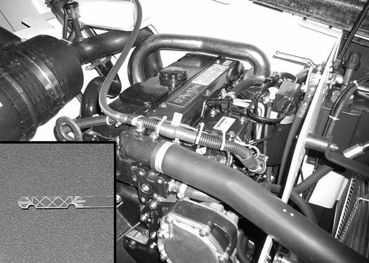
Engine Serial Number
The engine serial number is stamped on a plate near the injection pump or at the rear of the cylinder block Always use the full number when ordering replacement parts.
Other Serial Numbers
Some components may also have serial numbers. Always use these serial numbers when requesting parts.
CLICK HERE TO DOWNLOAD THE COMPLETE MANUAL
• Thank you very much for reading the preview of the manual.
• You can download the complete manual from: www.heydownloads.com by clicking the link below
• Please note: If there is no response to CLICKING the link, please download this PDF first and then click on it.
CLICK HERE TO DOWNLOAD THE
Delivery Report
Massey Ferguson Telehandler IDENTIFICATION
TELESCOPING BOOM BOOM TELESCOPING INDICATOR
The Delivery Report must be filled out by the dealer and signed by the owner or operator when the Telehandler is delivered. An explanation of the form must be given to the owner. Make sure it is filled out completely . B-15886 B-23131
BUCKET ATTACHMENT
BOOM ANGLE INDICATOR BOOM
MIRROR
OPERATOR HANDBOOK & LOAD CAPACITY CHARTS OPERATORS CAB (ROPS/FOPS)
SEAT BELT BOOM STOP
SAFETY TREAD (under boom, on top of frame)
LIGHT
TYRES (use only approved tyres at correct pressure)
ENGINE COVER LIGHTS
MIRROR
ALPHABETICAL INDEX
ACCUMULATOR.....................................................20-01
AIR CLEANER........................................................70-01
AIR CLEANER SERVICE.......................................10-01
AIR CONDITIONING SERVICE..............................80-01
AIR CONDITIONING SYSTEM FLOW...................80-01
ALTERNATOR.........................................................60-01
AXLE AND DIFFERENTIAL (FRONT)....................40-01
AXLE AND DIFFERENTIAL (REAR)......................40-01
AXLE PIVOT FRAME..............................................40-01
AXLE TOE-IN..........................................................40-01
AXLES (FRONT AND REAR).................................10-01
BASIC TROUBLESHOOTING...... .............80-01
BATTERY................................................................60-01
BOOM ASSEMBLY.................................................50-01
BOOM STOP..........................................................10-01
BRAKE LIGHT SWITCH .........................................60-01
BRAKE VALVE........................................................20-01
BUCKET POSITIONING CYLINDER......................20-01
GEAR PUMP...........................................................20-01
GENERAL AIR CONDITIONING SERVICE GUIDELINES.........................................................80-01
HEATER ASSEMBLY...............................................80-01
HYDRAULIC CONNECTION SPECIFICATION.SPEC-01 HYDRAULIC CONTROL VALVE..............................20-01
HYDRAULIC/HYDROSTATIC FLUID SPECIFICATIONS................ ...............SPEC-01
HYDRAULIC/HYDROSTATIC SYSTEM..................10-01
HYDRAULIC RESERVOIR......................................20-01
HYDRAULIC SYSTEM INFORMATION...................20-01
HYDROSTATIC DRIVE MOTOR..............................30-01
DASH COVERING/STEERING COLUMN COVER.50-01 DRIVE BOX.............................................................20-01
DRIVESHAFT........ ................40-01
ELECTRICAL SYSTEM INFORMATION................60-01
ENGINE AND ENGINE MOUNTS..........................70-01
ENGINE COMPONENTS AND TESTING..............70-01
ENGINE COOLING SYSTEM.................................10-01
ENGINE COVER..........................................10-01, 50-01
ENGINE/HYDROSTAT ASSEMBLY .............70-01
ENGINE LUBRICATION SYSTEM ..........................10-01
ENGINE SPECIFICATIONS...............................SPEC-01
ENGINE SPEED CONTROL...... ................70-01
EVAPORATOR/BLOWER UNIT..............................80-01
EXPANSION VALVE................................................80-01
EXTENSION CYLINDER........................................20-01
FAN MOTOR...........................................................20-01
FENDER.................................................................50-01
FLOW CONTROL VALVE.......................................20-01
FLYWHEEL AND HOUSING...................................70-01
FRAME LEVELING CYLINDER.... .............20-01
FRONT AUXILIARY HYDRAULIC PRESSURE RELEASE VALVE..................................................20-01
FRONT AXLE..........................................................40-01
FRONT AXLE WITH FRAME LEVELING...............40-01
FRONT WIPER MOTOR.........................................60-01
FUEL SYSTEM............. ................10-01
FUEL TANK.............................................................50-01
ALPHABETICAL INDEX (CONT’D)
SAFETY...................................................................80-01
SERVICE BRAKE....................................................40-01
SERVICE SCHEDULE.............................................10-01
STARTER.................................................................60-01
STEERING ANGLE ADJUSTMENTS......................40-01
STEERING CYLINDER (FRONT)...........................20-01
STEERING CYLINDER (REAR)..............................20-01
STEERING MODE VALVE BLOCK.........................20-01
STEERING VALVE..................................................20-01
SWITCH PANEL......................................................60-01
SYSTEM CHARGING & RECLAMATION................80-01
SYSTEM TROUBLESHOOTING.............................80-01
TEMPERATURE/PRESSURE...... .80-01
TIRE MAINTENANCE.............................................10-01
TILT CYLINDER.......................................................20-01
TOP WIPER MOTOR...............................................60-01
TORQUE SPECIFICATIONS FOR BOLTS........SPEC-01
TOW VALVE.............................................................20-01
TOWING THE TELEHANDLER...............................10-01
TRANSPORTING THE TELEHANDLER.................10-01
TRAVEL/SIGNAL LEVER........................................60-01
TROUBLESHOOTING..................................40-01, 70-01
TELEHANDLER SPECIFICATIONS..................SPEC-01
WEAR PADS (FRONT)............................................50-01
WEAR PADS (REAR)..............................................50-01
SAFETY AND MAINTENANCE
AIR CLEANER SERVICE
Replacing Filter Element
APPROVED BOOM STOP
Installing The Approved Boom Stop
Removing The Approved Boom Stop.
AXLES (FRONT AND REAR).
Checking Oil Level (Front Differential)
Checking Oil Level (Planetary Carrier)
Checking Oil Level (Rear Differential) .
Draining Oil (Front Differential)
Draining Oil (Planetary Carrier).
Draining Oil (Rear Differential).
ENGINE COOLING SYSTEM.
Checking The Coolant Level
Cleaning The Cooling System.
Replacing The Coolant
ENGINE COVER.
Opening And Closing The Engine Cover.
ENGINE LUBRICATION SYSTEM
Checking Engine Oil
Oil Chart.
Replacing Oil And Filter.
FUEL SYSTEM.
Filling The Fuel Tank
Fuel Filter.
Fuel Specifications.
HYDRAULIC/HYDROSTATIC SYSTEM
Checking And Adding Fluid
Replacing Hydraulic Fluid
Replacing Hydraulic/Hydrostatic Filter.
10-60-1
10-60-1
10-150-1
10-150-1
10-150-1
10-110-1
10-110-2
10-110-1
. 10-110-2
10-110-2
10-110-1
10-110-2
10-70-1
10-70-1
10-70-1
10-70-2
10-160-1
10-160-1
10-90-1
10-90-1
10-90-1
10-90-2
10-80-1
10-80-1
10-80-1
10-80-1
10-100-1
10-100-1
10-100-2
10-100-1
Continued On Next Page
LUBRICATION.
Procedure
OPERATOR CAB/CANOPY
Cab Door .
Cab Door Window
Emergency Exit
SERVICE SCHEDULE
SPARK ARRESTOR MUFFLER
Cleaning.
TYRE MAINTENANCE
Tyre Mounting
Tyre Rotation
Wheel Nuts
10-120-1
10-120-1
10-20-1
10-20-2
10-20-2
10-20-1
10-50-1
10-140-1
10-140-1
10-130-1
10-130-1
10-130-1
10-130-1
Procedure
Always park the machine on a level surface.
WARNING
Put jackstands under the front and rear axle before running the engine for service. Failure to use jackstands can allow the machine to fall or move and cause injury or death.
W-2461-0303
10-10-1

STOP the engine. Put the floor jack under the center of the front axle. Lift the Telehandler and install jackstands [Figure 10-10-1]
10-10-2

Put the floor jack under the center of the rear axle. Lift the Telehandler and install jackstands [Figure 10-10-2]
Figure
Figure
Figure 10-20-1
The TELEHANDLER has an operator cab or canopy (ROPS and FOPS) (Item 1) [Figure 10-20-1] to protect the operator from rollover and falling objects. Check with your dealer if the operator cab or canopy has been damaged. Never operate without right window. The seat belt must be worn for roll over protection.
ROPS/FOPS - Roll Over Protective Structure per SAE J1040 and ISO 3471, and Falling Object Protective Structure per SAE J1043 and ISO 3449 (FOPS Level II).
WARNING
Never modify operator cab or canopy by welding, grinding, drilling holes or adding attachments unless instructed to do so by Massey Ferguson. Do not operate without right window. Changes to the cab or canopy can cause loss of operator protection from rollover and falling objects, and result in serious injury or death.
W-2396-1202
Emergency Exit
Figure 10-20-2


Turn the handle (Inset) [Figure 10-20-2] and push the rear window open. (Models with enclosed cab only.) Exit through the rear window opening [Figure 10-20-2].
OPERATOR CAB/CANOPY (CONT’D)
Cab Door
Figure 10-20-3

Figure 10-20-4

The cab door can be opened from the outside of the cab using the latch (Item 1) [Figure 10-20-3] and open from the inside of the cab when you squeeze the latch (Item 1) [Figure 10-20-4] (as shown).
The cab door can be locked (Item 2) [Figure 10-20-3] with the start key.
Cab Door Window
Figure 10-20-5

Turn the handle (Item 1) [Figure 10-20-5] (as shown). Push open the window fully until it latches against the cab.
Figure 10-20-6

Pull the lever (Item 1) [Figure 10-20-6] inside the cab to disengage the latch and close the window.
P-47203
CLICK HERE TO DOWNLOAD THE COMPLETE MANUAL
• Thank you very much for reading the preview of the manual.
• You can download the complete manual from: www.heydownloads.com by clicking the link below
• Please note: If there is no response to CLICKING the link, please download this PDF first and then click on it.
CLICK HERE TO DOWNLOAD THE
Procedure
Always drive the Telehandler backwards (heavy end up) onto the transport vehicle.
Figure 10-30-1
The rear of the trailer must be blocked or supported [Figure 10-30-1] when loading or unloading the Telehandler to prevent the front end of the trailer from raising up.
Be sure the transport and towing vehicles are of adequate size and capacity. (See Contents Page Spec01 for weight of the Telehandler.
Fasten the Telehandler to the transport vehicle to prevent it from moving during sudden stops or when going up or down slopes.
•Block the wheels (Item 1) [Figure 10-30-1]
•Fasten the machine frame to the transport vehicle (Items 2 & 3) [Figure 10-30-1]
•Attach the forks or bucket attachment to the transport vehicle (Item 4) [Figure 10-30-1]
Adequately designed ramps of sufficient strength are needed to support the weight of the machine when loading onto a transport vehicle. Wood ramps can break and cause personal injury.
W-2058-0494
Procedure
The Telehandler can be towed a short distance such as removing it from mud or loading onto a transport vehicle.


Block the wheels to prevent the machine from rolling.
10-40-1

Releasing Brake Disks: To release the brake disks, turn each of the six (6) screws (Item 1) [Figure 10-40-1] in only one half turn at a time; then repeat until all six screws are all the way in. (It will take 4 & 1/2 to 5 turns to fully release the brakes.) Record the number of turns so that you can return them to the same position later.
NOTE: This procedure is required on the front axle only.
NOTE: If one screw is turned all the way in before you start turning the others, the brake can be damaged.
There are three screws on each side (right and left) located 120° apart [Figure 10-40-1]
Figure
TOWING THE TELEHANDLER (CONT’D)
Procedure (Cont’d)
Figure 10-40-2
OPERATING POSITION
POSITION

TOWING POSITION
Raise the engine cover.
Optional: Turn the tow valve counterclockwise 90° (Item 1) [Figure 10-40-2] to TOWING POSITION.
Tow the Telehandler at slow speed.
Engaging Brake Disks: After towing is completed, turn the tow valve (Item 1) [Figure 10-40-2] clockwise 90° to the OPERATING POSITION.
Turn all six screws out, 1/2 turn at a time, to their original position.
TOWING PROCEDURE
Before you tow a machine, you have to unscrew the by-pass for 2.5 turns.
Note : This action will not change the relief valve setting.

SERVICE SCHEDULE
Maintenance work must be done at regular intervals. Failure to do so will result in excessive wear and early failures. The service schedule is a guide for correct maintenance of the Massey Ferguson Telehandler.
WARNING
Instructions are necessary before operating or servicing machine. Read and understand the Operation & Maintenance Manual, Handbook and signs (decals) on machine. Follow warnings and instructions in the manuals when making repairs, adjustments or servicing. Check for correct function after adjustments, repairs or service. Untrained operators and failure to follow instructions can cause injury or death.
W-2003-0199
SERVICE SCHEDULE
Engine OilCheck the oil level and add oil as needed.
Hydraulic FluidCheck fluid level and add as needed.
Articulation PinsLubricate with multi-purpose lithium based grease.
Safety Signs, Safety Tread and Mirrors Check for damaged signs (decals), safety tread and mirrors. Replace if damaged or worn.
Fuel FilterClean the sediment bowl/water trap.
Nuts & BoltsCheck for loose nuts and bolts. Tighten as needed.
Seat Belt and Restraint Bar (if equipped)
Check the condition of the seat belt. Check the Restraint Bar (if equipped). Clean dirt and debris from moving parts.
BrakesCheck for function. Service as necessary.
Back-up AlarmCheck for function. Replace as necessary.
TyresCheck for wear or damage. Inflate to correct pressure. Be sure all tyres are inflated to the same pressure. Use only approved tyres.
Engine Air Filter And Air SystemCheck condition indicator, replace element when required and empty dust cup as needed. Check air system for leaks.
Engine Cooling SystemClean debris from oil cooler, radiator and air conditioner condenser. check coolant level cold in reservoir. Add premixed coolant as needed (See ENGINE COOLING SYSTEM, Page PM-16). Check cooling system for leaks.
King Pins, U-Joints, Axle Oscillation (Front/Rear), Attach. Frame
Pivot(s), Tilt/Lift Cyl., Boom Pivot, Leveling Cyl. (if equipped)
Lubricate with multi-purpose lithium based grease.
Telescopic Boom SlideLubricate with multi-purpose lithium based grease. Check wear blocks for adjustment or replacement.
Hydraulic Hoses, Tubelines & Connections Check condition of hoses, tubelines and connectors. Repair or replace as needed.
BatteryCheck electrolyte level. Add distilled water as needed.
Wheel NutsCheck wheel nut torque. Tighten as needed [221 ft.-lbs. (300 Nm)].
Restraint Bar Spring PivotLubricate with multi-purpose lithium based grease.
Alt. & Air Cond. Belt (if equipped)Check belt tension and adjust as needed.
Engine Oil and FilterReplace the engine oil and filter. See SPECIFICATIONS Page SPEC-01 for correct capacity. Use a genuine Massey Ferguson filter.
Engine Air FilterReplace the outer filter element. Use a genuine Massey FergusonMassey Ferguson filter.
Fuel FilterReplace the fuel filter element. Use a genuine Massey Ferguson filter.
Hydraulic Fluid FilterReplace the hydraulic filter element. Use a genuine Massey Ferguson filter.
Hydrostatic Fluid FilterReplace the hydraulic filter element. Use a genuine Massey Ferguson filter.
Hydraulic Fluid and Filter Replace the hydraulic fluid and filter element. See SPECIFICATIONS
Front & Rear Axle FluidReplace the axle fluid. See SPECIFICATIONS
Engine CoolantCheck freeze protection of antifreeze -34 F (-30 C). Flush cooling system and replace with premixed coolant (See ENGINE COOLING SYSTEM, PM-16).
Telescopic Boom Wear BlocksCheck for wear and adjust as needed. Replace as necessary.
Pivot Pins and BushingsCheck for wear on the pivot pins and bushings.
Check wheel nut torque every 8 hours for the first 24 hours. Perform service first time, then as indicated in chart. Check level.
Replace fluid first time, then as indicated in chart. Or every 6 months Or every 12 months
AIR CLEANER SERVICE
Replacing Filter Element
Figure 10-60-1

Replace the large (outer) filter element only when the red ring shows in the window of the condition indicator (Item 1) [Figure 10-60-1]
NOTE: Before replacing the filter element, push the button on the condition indicator (Item 2) [Figure 10-60-1]. Start the engine. If the red ring does not show, do not replace the filter element.
Replace the inner filter every third time the outer filter is replaced or when the red ring still shows in the indicator window after the outer filter has been replaced.
Figure 10-60-2

Loosen the filter housing clamps (Item 1) [Figure 10-602]
Release the fastener and remove the cover (Item 2) [Figure 10-60-2]
Figure 10-60-3

Pull the element straight out [Figure 10-60-3]
NOTE: Make sure all sealing surfaces are free of dirt and debris.
Install a new outer element.
Install the dust cover and fasten[Figure 10-60-3]
Connect the filter housing clamps.
P-50805
CLICK HERE TO DOWNLOAD THE COMPLETE MANUAL
• Thank you very much for reading the preview of the manual.
• You can download the complete manual from: www.heydownloads.com by clicking the link below
• Please note: If there is no response to CLICKING the link, please download this PDF first and then click on it.
CLICK HERE TO DOWNLOAD THE
AIR CLEANER SERVICE (CONT’D)
Replacing Filter Element (Cont’d)
Inner Filter
Remove the outer element.
NOTE: Make sure all sealing surfaces are free of dirt and debris.
Figure 10-60-4

Remove the inner filter (Item 1) [Figure 10-60-4] and install a new element.
Install the outer element.
Install the dust cover and fasten [Figure 10-60-4]
Connect the filter housing clamp (Item 1) [Figure 10-604]
ENGINE COOLING SYSTEM
Check the cooling system every day to prevent overheating, loss of performance or engine damage.
WARNING
Wear safety glasses to prevent eye injury when any of the following conditions exist:
•When fluids are under pressure.
•Flying debris or loose material is present.
•Engine is running.
•Tools are being used.
Cleaning The Cooling System
Figure 10-70-1
W-2019-1285
Checking The Coolant Level
Open the engine cover.
Check the coolant level in the coolant reservoir.
Figure 10-70-3

The coolant level must be between the MIN and MAX marks (Item 1) [Figure 10-70-3] on the coolant reservoir when the engine is cold.
Close the engine cover.
IMPORTANT
AVOID ENGINE DAMAGE
Always use the correct ratio of water to antifreeze.
Open the engine cover (Item 1) [Figure 10-70-1]
Figure 10-70-2

Use low air pressure or water pressure to clean the radiator and oil cooler [Figure 10-70-2]
To much antifreeze reduces cooling system efficiency and may cause serious premature engine damage.
Too little antifreeze reduces the additives which protect the internal engine components; reduces the boiling point and freeze protection of the system.
Always add a premixed solution. Adding full strength concentrated coolant can cause serious premature engine damage.
ENGINE COOLING SYSTEM (CONT’D)
Replacing The Coolant WARNING
AVOID BURNS
Do not remove radiator cap when the engine is hot. You can be seriously burned.
W-2070-1203
Figure 10-70-5
Open the engine cover.
Figure 10-70-4
Remove the cap (Item 1) [Figure 10-70-4] from the coolant reservoir.
Remove the fan shield.
IMPORTANT
AVOID ENGINE DAMAGE
Always use the correct ratio of water to anti freeze. Too much antifreeze reduces cooling system efficiency and may cause serious premature engine damage. Too little antifreeze reduces the additives which protect the internal engine compo nents; reduces the boiling point and freeze protection of the system. Always add a premixed solution. Adding full strength concentrated coolant can cause serious premature engine damage.
I-2124-0497

Remove the engine block drain plug (Item 1) [Figure 1070-5]
Open the drain valve (Item 2) [Figure 10-70-5] and drain all of the coolant into a container. Dispose of used coolant in an environmentally safe manner.
Close the drain valve.
Mix the coolant in a separate container.
NOTE: The Telehandler is factory filled with ethylene glycol coolant.
Add premixed coolant, 50% water and 50% ethylene glycol to the reservoir if the coolant level is low.
One gallon (3,8 L) of ethylene glycol mixed with one gallon (3,8 L) of water is the correct mixture of coolant to provide a -34° F (-37° C) freeze protection.
Use a refractometer to check the condition of ethylene glycol in your cooling system.
Fill the radiator with the premixed coolant. Install the radiator cap.
Add coolant to the reservoir. The coolant level must be between the MIN and MAX marks (Item 2) [Figure 1070-4] on the coolant reservoir.
Run the engine until it is at operating temperature. Stop the engine.
Check the coolant level (cold) in the reservoir when cool.
Add coolant as needed.
FUEL SYSTEM
Fuel Specifications
Use only clean, high quality diesel fuel, Grade No. 2 or Grade No. 1.
The following is one suggested blending guideline which should prevent fuel gelling problems in cold temperatures:
Fuel Filter
See the SERVICE SCHEDULE Content Page 10-01 for the service interval when to clean the sediment bowl.
Figure 10-80-2
Down to -20° (-29°)50%50%
Below -20° (-29°)0%100%
See your fuel supplier for local recommendations.
Filling The Fuel Tank
WARNING
Stop and cool the engine before adding fuel. NO SMOKING! Failure to obey warnings can cause an explosion or fire.
W-2063-0887

See the SERVICE SCHEDULE Page 10-01 for the service interval when to replace the fuel filter.
Remove the filter element (Item 1) [Figure 10-80-2]
Clean the area around the filter housing.
Put oil on the seal of the new filter element.
Figure 10-80-1

Remove the fuel fill cap (Item 1) [Figure 10-80-1]
Use a clean, approved safety container to add fuel of the correct specifications. Add fuel only in an area that has free movement of air and no open flames or sparks. NO SMOKING!
Install and tighten the fuel fill cap [Figure 10-80-1]
Install the fuel filter, and hand tighten.
WARNING
Always clean up spilled fuel or oil. Keep heat, flames, sparks or lighted tobacco away from fuel and oil. Failure to use care around combustibles can cause explosion or fire which can result in injury or death.
W-2103-1285
ENGINE LUBRICATION SYSTEM
Checking Engine Oil
Check the engine oil level every day before starting the engine for the work shift.
Figure 10-90-1

Open the engine cover and remove the dipstick (Item 1) [Figure 10-90-1].
Keep the oil level between the marks on the dipstick (Inset) [Figure 10-90-1]
Use a good quality motor oil that meets API Service Classification of CD or better. (See Oil Chart , [Figure 10-90-2].)
Oil Chart
Figure 10-90-2
RECOMMENDED SAE VISCOSITY NUMBER (LUBRICATION OILS FOR DIESEL ENGINE CRANKCASE)

P-52253
ENGINE LUBRICATION SYSTEM (CONT’D)
Replacing Oil And Filter
See the SERVICE SCHEDULE Page 10-01 for the service interval for replacing the engine oil and filter.
Run the engine until it is at operating temperature. Stop the engine.
Figure 10-90-3

Remove the access panel at the rear of the engine compartment. Route the hose (Item 1) [Figure 10-90-3] out through the access hole. Remove the cap.
Drain the oil into a container and recycle or dispose of used oil in an environmentally safe manner.
Install cap and put the drain hose into the engine compartment, install the access cover.
WARNING
Always clean up spilled fuel or oil. Keep heat, flames, sparks or lighted tobacco away from fuel and oil. Failure to use care around combustibles can cause explosion or fire which can result in injury or death. W-2103-1285
Figure 10-90-4

Open the engine cover.
Remove the oil filter (Item 1) [Figure 10-90-4]
Clean the filter housing surface.
Put clean oil on the new oil filter gasket. Install the filter and hand tighten.
Figure 10-90-5
Remove the filler cap (Item 1) [Figure 10-90-5].
Put oil in the engine. (See SPECIFICATIONS Page SPEC-01, for Capacity). (See Oil Chart, Page 10-90-1.)
Install fill cap, start the engine and let it run for several minutes.
Stop the engine, and check for leaks at the oil filter.
Remove the dipstick (Item 2) [Figure 10-90-5] and check the oil level. Add oil as needed if it is not at the top mark [Figure 10-90-5] on the dipstick.
HYDRAULIC/HYDROSTATIC SYSTEM
Checking And Adding Fluid
Use only recommended fluid in the hydraulic system. (See SPECIFICATIONS Page SPEC-01.)
Stop the machine on a level surface. Lower the boom all the way.
Stop the engine.
Figure 10-100-1

Check the fluid level at the sight gauge (Item 1) [Figure 10-100-1]
Remove the fill cap (Item 2) [Figure 10-100-1].
Figure 10-100-2

When adding oil, slowly pour the oil through the filter as needed, until visible in the sight gauge (Item 1) [Figure 10-100-2]
Replacing Hydraulic/Hydrostatic Filter
See the SERVICE SCHEDULE Page 10-01 for the correct service intervals.
Open the engine cover and remove the fill cap (Item 2) [Figure 10-100-1]
Figure 10-100-3

Remove the filter element (Item 1) [Figure 10-100-3].
Clean the surface of the filter housing where the seal contacts the housing.
Put clean oil on the seal of the new filter element.
Install and hand tighten the filter element.
WARNING
Diesel fuel or hydraulic fluid under pressure can penetrate skin or eyes, causing serious injury or death. Fluid leaks under pressure may not be visible. Use a piece of cardboard or wood to find leaks. Do not use your bare hand. Wear safety goggles. If fluid enters skin or eyes, get immediate medical attention from a physician familiar with this injury.
W-2072-0496
WARNING
Always clean up spilled fuel or oil. Keep heat, flames, sparks or lighted tobacco away from fuel and oil. Failure to use care around combustibles can cause explosion or fire which can result in injury or death.
W-2103-1285
HYDRAULIC/HYDROSTATIC SYSTEM (CONT’D)
Replacing Hydraulic Fluid
Figure 10-100-4
Remove the fill cap (Item 1) [Figure 10-100-4]
Figure 10-100-5

Remove the reservoir drain plug (Item 1) [Figure 10-1005] behind the right front wheel and drain the fluid into a container. Recycle or dispose of the fluid in an environmentally safe manner. Reinstall the drain plug and tighten.
Add fluid until it is at the center of the sight gauge (Item 2) [Figure 10-100-4]
Install the fill cap.
CLICK HERE TO DOWNLOAD THE COMPLETE MANUAL
• Thank you very much for reading the preview of the manual.
• You can download the complete manual from: www.heydownloads.com by clicking the link below
• Please note: If there is no response to CLICKING the link, please download this PDF first and then click on it.
CLICK HERE TO DOWNLOAD THE
AXLES (FRONT AND REAR)
Checking Oil Level (Planetary Carrier)
Figure 10-110-1

Put the machine on a level surface with the plug (Item 1) [Figure 10-110-1] positioned as shown.
Remove the plug (Item 1) [Figure 10-110-1]. The oil level should be at the bottom edge of the plug hole.
Add gear lube through the hole if the oil level is below the hole. (See FUEL, COOLANT AND LUBRICANT Chart, Content Page SPEC-01 for capacity and type.)
Install and tighten the plug.
Repeat the procedure for the other side.
Draining Oil (Planetary Carrier)
See the SERVICE SCHEDULE Content Page 10-01 for the correct service interval.
Figure 10-110-2

Put the machine on a level surface with the plug (Item 1) [Figure 10-110-2] positioned as shown.
Remove the plug (Item 1) [Figure 10-110-2] and drain into a container. Recycle or dispose of the used lubricant in an environmentally safe manner.
Reposition the plug hole and add gear lube until the lube level is at the bottom edge of the plug hole (Item 1) [Figure 10-110-1]. (See FUEL, COOLANT AND LUBRICANT Chart, Content Page SPEC-01 for capacity and type.)
Install and tighten the plug.
Repeat the procedure for the other side.
AXLES (FRONT AND REAR) (CONT'D)
Checking Oil Level (Rear Differential)
Figure 10-110-3

With the machine on a level surface, remove the plug (Item 1) [Figure 10-110-3]. The oil level should be at the bottom edge of the plug hole.
Add oil through the hole if the oil level is below the hole. (See FUEL, COOLANT AND LUBRICANT Chart, Content Page SPEC-01 for capacity and type.)
Install and tighten the plug.
Draining Oil (Rear Differential)
See the SERVICE SCHEDULE Content Page 10-01 for the correct service interval.
Figure 10-110-4

With the machine on a level surface remove the plug (Item 1) [Figure 10-110-4] and drain into a container. Recycle or dispose of the used lubricant in an environmentally safe manner.
Checking Oil Level (Front Differential)
Figure 10-110-5

Put the machine on a level surface with the plugs (Item 1) [Figure 10-110-5] positioned as shown.
Remove the plugs (Item 1) [Figure 10-110-5]. The oil level should be at the bottom edge of the plug hole.
Add oil through the hole if the oil level is below the hole. (See FUEL, COOLANT AND LUBRICANT Chart, Content Page SPEC-01 for capacity and type.)
Install and tighten the plug.
Draining Oil (Front Differential)
See the SERVICE SCHEDULE Content Page 10-01 for the correct service interval.
Figure 10-110-6

With the machine on a level surface, remove the plug (Item 1) [Figure 10-110-6] and drain into a container. Recycle or dispose of the used lubricant in an environmentally safe manner.
LUBRICATION
Procedure
Lubricate as specified in the SERVICE SCHEDULE, See Contents Page 10-01 for the best performance of the machine.
Record the operating hours each time you lubricate so that it is performed at the correct interval.
Always use a good quality lithium based multi-purpose grease. Apply lubricant until extra grease shows.
Lubricate the following locations on the Telehandler:
10-120-1

Figure 10-120-2
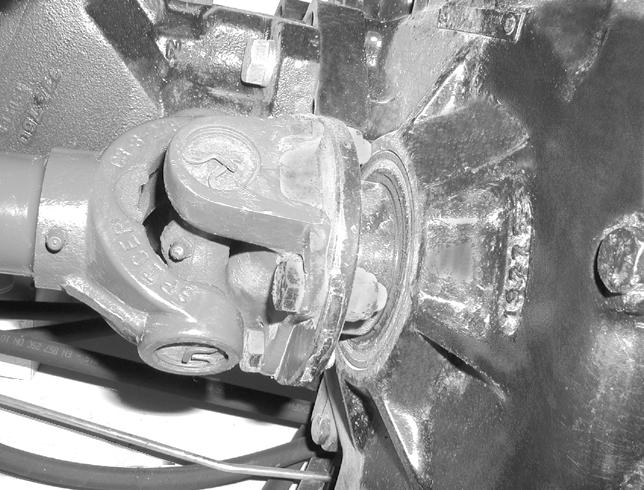

Figure 10-120-3


Figure
1.Axle Pivots - Top and bottom (Item 1) [Figure 10-1201] all four wheels.
2.UniTELEl Joints - Front and Rear (Item 1) [Figure 10120-2]
3.Axle Oscillation - Rear Axle (Item 1) [Figure 10-1203]
Figure 10-120-4
4.Attachment Frame Pivot (Item 1) [Figure 10-120-4] P-24167
LUBRICATION (CONT'D)
Procedure (Cont’d)
Figure 10-120-5

5.Lower Pivot Link (Item 1) [Figure 10-120-5]
Figure 10-120-6

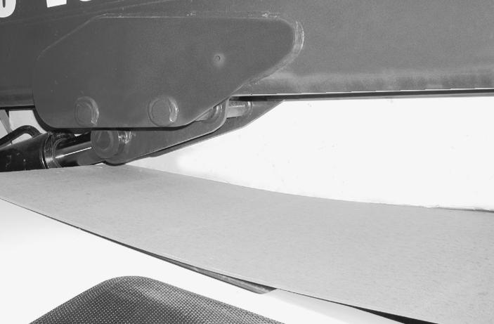
6.Remove the two cover bolts (Item 1) and cover (Item 2) [Figure 10-120-6]
Figure 10-120-7

7.Main Pivot Link (Item 1) [Figure 10-120-7].
10-120-8

8.Extension Cylinder Rod End (Item 1) [Figure 10-1208].
Figure
LUBRICATION (CONT'D)
Procedure (Cont’d)
Figure 10-120-9

NOTE: Raise the boom and install the boom stop (See Boom Stop Installation Content Page 10-01) before lubricating the boom cylinder.
9.Lift Cylinder Rod End (Item 1) [Figure 10-120-9].
Figure 10-120-10

10.Lift Cylinder Base End (Item 1) [Figure 10-120-10]
NOTE: The rear cover must be removed.
Figure 10-120-11

NOTE: The rear cover must be removed.
Figure 10-120-12

NOTE: The rear cover must be removed.
11.Base End Slave Cylinder (Item 1) [Figure 10-120-11]
12.Slave Cylinder Pivot Bracket (Item 1) [Figure 10-12012]
LUBRICATION (CONT'D)
Procedure (Cont’d)
Figure 10-120-13

13.Boom Pivot (Item 1) [Figure 10-120-13] (Four Places).
Figure 10-120-14

14.Boom Slide [Figure 10-120-14] (Four Places).
10-120-15

15.Axle Oscillation - Front Axle (Item 1) [Figure 10-12015] (With Frame Leveling Only)
Figure
P-34461A
TYRE
Wheel Nuts
Figure 10-130-1

See the SERVICE SCHEDULE Content Page 10-01 for the service interval to check the wheel nuts. The correct torque is 221 ft.-lbs. (300 Nm) torque [Figure 10-130-1]
Tyre Rotation
Check the tyres regularly for wear, damage and pressure. (See Content Page SPEC-01 for the correct tyre pressure.)
Rear tyres usually wear faster than front tyres. To keep the wear even, move the front tyres to the rear and rear tyres to the front.
It is important to keep the same size tyres on each side of the loader. If different sizes are used, each tyre will be turning at a different rate and cause excessive wear. The tread bars of all the tyres must face the same direction.
Recommended tyre pressure must be maintained to avoid excessive tyre wear and loss of stability and handling capability. Check for the correct pressure before operating the loader.
Tyre Mounting
Do not inflate tyres above specified pressure. Failure to use correct tyre mounting procedure can cause an explosion which can result in injury or death.
W-2078-1285
Tyres are to be repaired only by an authorized person using the correct procedures and type of equipment.
Tyres and rims must always be checked for correct size before mounting. Check rim and tyre bead for damage. The rim flange must be cleaned and free of rust. The tyre bead and rim flange must be lubricated with a rubber lubricant before mounting the tyre.
Avoid excessive pressure which can rupture the tyre and cause serious injury or death.
During inflation of the tyre, check the tyre pressure frequently to avoid over inflation.
Cleaning
See the SERVICE SCHEDULE Content Page 10-01 for the service interval for cleaning the spark arrestor muffler.
Do not operate the machine with a defective exhaust system.
Stop the engine.
Figure 10-140-2

Remove the plug (Item 1) [Figure 10-140-2] from the bottom of the muffler.
WARNING
When the engine is running during service, the Travel Direction Lever must be in neutral and the parking brake engaged. Failure to do so can cause injury or death.
W-2397-0301
Start the engine and run for about 10 seconds while a second person, wearing safety glasses, holds a piece of wood over the outlet of the muffler.
This will force contaminants out through the clean out hole.
Stop the engine.
Install and tighten the plug.
IMPORTANT
This loader is factory equipped with a U.S.A.. Forestry Service approved spark arrestor muffler. It is necessary to do maintenance on this spark arrestor muffler to keep it in working condition. The spark arrestor muffler must be serviced by dumping the spark chamber every 100 hours of operation. If this machine is operated on flammable forest, brush or grass covered land, it must be equipped with a spark arrestor attached to the exhaust system and maintained in working order. Failure to do so will be in violation of California State Law, Section 4442 PRC.
Make reference to local laws and regulations for spark arrestor requirements.
I-2022-0595
CLICK HERE TO DOWNLOAD THE COMPLETE MANUAL
• Thank you very much for reading the preview of the manual.
• You can download the complete manual from: www.heydownloads.com by clicking the link below
• Please note: If there is no response to CLICKING the link, please download this PDF first and then click on it.
CLICK HERE TO DOWNLOAD THE
APPROVED BOOM STOP
If the boom is raised for service or maintenance, use the following procedure to install and remove the boom stop.
Installing The Approved Boom Stop
•Put the Telehandler on a flat, solid and level surface.
•With the operator in the seat, the restraint bar lowered, (if equipped) seat belt fastened, Travel Direction Control in neutral and the parking brake engaged, start the engine and raise the boom. Stop the engine.
10-150-1

•Have a second person remove the boom stop (Item 1) [Figure 10-150-1] from the storage position.
Figure 10-150-2
•Install the boom stop over the rod of the boom cylinder [Figure 10-150-2]
•Install the pins and secure the fasteners [Figure 10150-2].
•Start the engine and lower the boom slowly [Figure 10-150-2] so that the boom stop is held securely.
Removing The Approved Boom Stop
•Start the engine lower the restraint bar (if equipped) and raise the boom. Stop the engine.
•Remove the fasteners, pins and boom stop.
•Put the boom stop in the storage position and secure with pins and fasteners.
•Start the engine lower the restraint bar (if equipped) and lower the boom
Figure
AVOID INJURY OR DEATH
Never service or adjust the machine when the engine is running unless instructed to do so in the manual.
W-2012-0497
Opening And Closing The Engine Cover
Figure 10-160-1

Pull up on the latch handle (Item 1) [Figure 10-160-1] and rotate counterclockwise to release latch.
ACCUMULATOR.
HYDRAULIC SYSTEM
Removal And Installation.
BRAKE VALVE
Disassembly And Assembly. .
Removal And Installation.
BUCKET POSITIONING CYLINDER
Assembly.
Disassembly.
Parts Identification.
Removal And Installation.
DRIVE BOX.
Assembly.
Disassembly.
Inspection.
Parts Identification.
EXTENSION CYLINDER
Assembly.
Cylinder Group Removal And Installation
Disassembly.
Extension Cylinder Removal And Installation
Parts Identification.
Tubeline Tray Assembly.
Tubeline Tray Disassembly.
Upper Tubeline Installation.
Upper Tubeline Removal
FAN MOTOR.
Not Available At Time Of Printing.
FLOW CONTROL VALVE
Removal And Installation.
FRAME LEVELING CYLINDER
Assembly.
Disassembly.
Parts Identification.
Removal And Installation.
GEAR PUMP.
Not Available At Time Of Printing.
Continued On Next Page
20-210-1
20-210-1
20-120-1
20-120-2
20-120-1
20-30-1
20-30-9
20-30-5
20-30-4
20-30-1
20-70-1
20-70-8
20-70-2
20-70-7
20-70-1
20-40-1
20-40-18
20-40-1
20-40-14
20-40-5
20-40-13
20-40-9
20-40-7
20-40-3
20-40-3
20-140-1
20-140-1
20-172-1
20-172-1
20-100-1
20-100-9
20-100-4
20-100-3
20-130-1
HYDRAULIC SYSTEM
HYDRAULIC CONTROL VALVE.
20-170-1
Auxiliary/Frame Leveling Valve Section Disassembly And Assembly . . . 20-170-31
Disassembly And Assembly.
End Housing Disassembly And Assembly.
Inlet-Outlet Valve Section Disassembly And Assembly
Lifting Valve Section Disassembly And Assembly
Parts Identification. .
Removal And Installation.
Telescoping Valve Section Disassembly And Assembly
Tilting Valve Section Disassembly And Assembly
HYDRAULIC RESERVOIR
Not Available At Time Of Printing
HYDRAULIC SYSTEM INFORMATION
Tightening Procedures.
Troubleshooting Chart
JOYSTICK.
Disassembly And Assembly.
Handle Removal And Installation.
Joystick Removal And Installation
Parts Identification.
LIFT CYLINDER
Assembly.
Disassembly.
Parts Identification.
Removal And Installation.
MAIN RELIEF VALVE
Removal and Installation
Testing And Adjustment.
PARKING BRAKE.
Parking Brake Valve Disassembly And Assembly
Parking Brake Valve Removal And Installation
Pressure Switch Disassembly And Assembly
Pressure Switch Removal And Installation
PORT RELIEF VALVES.
Adjustment Procedure.
Continued On Next Page
20-170-6
20-170-7
20-170-41
20-170-8
20-170-5
20-170-1
20-170-18
20-170-13
20-150-1
20-150-1
20-10-1
20-10-5
20-10-4
20-180-1
20-180-5
20-180-1
20-180-2
20-180-4
20-20-1
20-20-11
20-20-6
20-20-5
20-20-1
20-80-1
20-80-2
20-80-1
20-190-1
20-190-5
20-190-4
20-190-3
20-190-1
20-171-1
20-171-1
HYDRAULIC SYSTEM (CONT’D)
PRESSURE REDUCING VALVE
Disassembly And Assembly.
Removal And Installation.
Testing
QUICK TACH CYLINDER
Assembly. .
Disassembly.
Parts Identification.
Removal And Installation.
STEERING CYLINDER (FRONT).
Assembly.
Disassembly.
Parts Identification.
Removal And Installation.
STEERING CYLINDER (REAR).
Assembly.
Disassembly.
Parts Identification.
Removal And Installation.
STEERING MODE VALVE BLOCK.
Assembly.
Disassembly.
Parts Identification.
Removal And Installation.
Solenoid Testing.
STEERING VALVE
Assembly.
Disassembly.
Inspection.
Parts Identification.
Removal And Installation.
TILT CYLINDER
Assembly.
Disassembly.
Parts Identification.
Removal And Installation.
TOW VALVE
Not Available At Time Of Printing.
20-200-1
20-200-3
20-200-2
20-200-1
20-90-1
20-90-7
20-90-4
20-90-3
20-90-1
20-60-1
20-60-7
20-60-4
20-60-3
20-60-1
20-61-1
20-61-7
20-61-4
20-61-3
20-61-1
20-110-1
20-110-6
20-110-4
20-110-3
20-110-1
20-110-6
20-160-1
20-160-9
20-160-3
20-160-9
20-160-2
20-160-1
20-50-1
20-50-7
20-50-3
20-50-2
20-50-1
20-220-1
20-220-1
CLICK HERE TO DOWNLOAD THE COMPLETE MANUAL
• Thank you very much for reading the preview of the manual.
• You can download the complete manual from: www.heydownloads.com by clicking the link below
• Please note: If there is no response to CLICKING the link, please download this PDF first and then click on it.
CLICK HERE TO DOWNLOAD THE
Troubleshooting Chart
The following troubleshooting chart is provided for assistance in locating and correcting problems which are most common. Many of the recommended procedures must be done by authorized Massey Ferguson Service Personnel only.
Check for correct function after adjustments, repairs or service. Failure to make correct repairs or adjustments can cause injury or death. W-2004-1285
PROBLEMCAUSE
The hydraulic system will not operate.1, 2, 3, 6 The hydraulic oil temperature warning light comes ON when hydraulics are operating.1, 2 Slow hydraulic system action.1, 2, 4, 8 Hydraulic action is not smooth.1, 3, 4, 5 Boom goes up slowly at full engine RPM.1, 2, 4, 5, 6, 7 The boom comes down with the lever in neutral position.7, 8, 9
KEY TO CORRECT THE CAUSE
1. The fluid level is not correct..
2. The hydraulic pump has damage.
3. Relief valve is not at the correct pressure.
4. Suction leak on the inlet side of the hydraulic pump.
5. Fluid is cold. Wrong viscosity fluid. (See Section SPEC-01.)
6. Using the machine for more than its rated capacity.
7. Internal leak in the lift cylinder.
8. External leak from the cylinder(s).
9. Damaged lift spool.
Tightening Procedures
IMPORTANT
When repairing hydrostatic and hydraulic systems, clean the work area before disassembly and keep all parts clean. Always use caps and plugs on hoses, tubelines and ports to keep dirt out. Dirt can quickly damage the system.
I-2003-0888
To tighten the hydraulic fittings, tubelines etc. See Spec Section - Hydraulic Connection Specifications, for the correct procedure and torque.
WARNING
Hydraulic fluid escaping under pressure can have sufficient force to enter a person’s body by penetrating the skin. This can cause serious injury and possible death if proper medical treatment by a physician familiar with this injury is not received immediately.
W-2145-0290
LIFT CYLINDER
Removal And Installation
Figure 20-20-1

Lower the boom onto adequate stands or blocks as shown [Figure 20-20-1]
Remove the rear cover from the machine.
Figure 20-20-2

Place a wood block (Item 1) [Figure 20-20-2] under the lift cylinder.
20-20-3

Remove the pivot pin retainer bolt (Item 1) [Figure 20-203] from the rod end.
Figure
P-29763
P-29765
P-29764
Removal And Installation (Cont'd)
Figure 20-20-4

Remove the upper pivot pin using a pin removal tool (Item 1) [Figure 20-20-4]
NOTE: If a nut must be welded onto the pin for removal the following three steps must be performed.
Figure 20-20-5

1.Rotate the battery disconnect switch (Item 1) [Figure 20-20-5] to the right to disconnect the power supply from the battery.
20-20-6
2.The side window (Item 1) and frame opening (Item 2) [Figure 20-20-6] must be protected from sparks.
20-20-7

3.The cylinder rod must be wrapped with a damp welding blanket (Item 1) [Figure 20-20-7] to prevent damage.
Figure
Figure
LIFT CYLINDER (CONT'D)
Removal And Installation (Cont'd)
Figure 20-20-8

After the upper pivot pin has been removed, the rod end of the cylinder should be lowered onto the center frame with a pipe (Item 1) [Figure 20-20-8] positioned as shown.
Figure 20-20-9

Remove the two hoses (Item 1) [Figure 20-20-9] from the lift lock on the lift cylinder.
NOTE: Mark all hoses for correct installation.
IMPORTANT
When repairing hydrostatic and hydraulic systems, clean the work area before disassembly and keep all parts clean. Always use caps and plugs on hoses, tubelines and ports to keep dirt out. Dirt can quickly damage the system.
I-2003-0888
Figure 20-20-10

Remove the base end pivot pin snap ring (Item 1) [Figure 20-20-10]
Figure 20-20-11

Remove the bolt (Item 1) (both sides) and remove the cross brace (Item 2) [Figure 20-20-11]
Installation: Tighten the bolt to 255 ft.-lbs. (345 Nm) torque.
P-50974
P-50973
CLICK HERE TO DOWNLOAD THE COMPLETE MANUAL
• Thank you very much for reading the preview of the manual.
• You can download the complete manual from: www.heydownloads.com by clicking the link below
• Please note: If there is no response to CLICKING the link, please download this PDF first and then click on it.
CLICK HERE TO DOWNLOAD THE
LIFT CYLINDER (CONT'D)
Removal And Installation (Cont'd)
Figure 20-20-12

Lift and support the base end of the cylinder [Figure 2020-12]
Figure 20-20-13

Remove the base end pivot pin (Item 1) [Figure 20-2013]
20-20-14

Lift and remove the cylinder [Figure 20-20-14]
Figure
P-50975 P-29776
P-29779A
LIFT CYLINDER (CONT'D)
Parts Identification
1.Housing
2.Bushing
3.Spacer
4.Grease Fitting
5.Wiper
6.Wear Ring
7.Seal
8.O-ring
9.Rod
10.Head
11.Piston
12.Lock Washer
13.Nut

LIFT CYLINDER (CONT'D)
Disassembly
Figure 20-20-15

Use the following tools to disassemble the cylinders:
MEL1354-Spanner Wrench
MEL1076-Cylinder Wrench
Put the cylinder in a vise [Figure 20-20-15].
Figure 20-20-16

Remove the four bolts (Item 1) and remove the lift lock (Item 2) [Figure 20-20-16].
Figure 20-20-17

Carefully peen the lock ring from the head gland [Figure 20-20-17]
Figure 20-20-18

Use a spanner wrench to loosen the head gland [Figure 20-20-18]
P-29903 P-29904
P-29905
P-29906
LIFT CYLINDER (CONT'D)
Disassembly (Cont'd)
Figure 20-20-19

Remove the rod assembly (Item 1) [Figure 20-20-19] from the housing.
Figure 20-20-20

Put the rod end of the cylinder in a vise [Figure 20-2020]
Figure 20-20-21

Support the cylinder rod on a wood block [Figure 20-2021]
Figure 20-20-22

Carefully peen the lock ring tab (Item 1) [Figure 20-2022] up and out of the lock nut groove.
P-29907
P-29909
P-29910
P-29923
LIFT CYLINDER (CONT'D)
Disassembly (Cont'd)
Figure 20-20-23

Remove the lock nut from the cylinder rod [Figure 20-2023] using a cylinder wrench.
Figure 20-20-24

Remove the lock ring (Item 1) [Figure 20-20-24]
Figure 20-20-25

Remove the piston (Item 1) [Figure 20-20-25] from the rod.
Figure 20-20-26

Remove the two wear rings (Item 1) and seal (Item 2) [Figure 20-20-26] from the piston.
P-29914
P-29915
LIFT CYLINDER (CONT'D)
Disassembly (Cont'd)
Figure 20-20-27

Remove the expander O-ring (Item 1) [Figure 20-20-27]
Figure 20-20-28

Remove the O-ring (Item 1) [Figure 20-20-28] from the piston.
Figure 20-20-29

Remove the head gland (Item 1) [Figure 20-20-29] from the rod.
Figure 20-20-30

Remove the two O-rings (Item 1) [Figure 20-20-30] from the head gland.
P-29918
P-29919
LIFT CYLINDER (CONT'D)
Disassembly (Cont'd)
Figure 20-20-31

Remove the wear ring (Item 1) [Figure 20-20-31]
Figure 20-20-32

Remove seal (Item 1) wear ring (Item 2) and wiper (Item 3) [Figure 20-20-31] from the head gland.
P-29920
P-29921
CLICK HERE TO DOWNLOAD THE COMPLETE MANUAL
• Thank you very much for reading the preview of the manual.
• You can download the complete manual from: www.heydownloads.com by clicking the link below
• Please note: If there is no response to CLICKING the link, please download this PDF first and then click on it.
CLICK HERE TO DOWNLOAD THE