BI001570
A6474X393
September 2012

BI001570
A6474X393
September 2012
A6474X393 (Obelix Control System Display)
This manual is intended to provide GENERAL product information. The illustrations, descriptions and procedures contained in this publication apply only to THIS machine. Caterpillar reserves the right to revise models and designs without prior notice.
This machine was manufactured under the guidelines, procedures and requirements of the appropriate government regulatory agencies.
At the completion of the manufacturing process, this unit was issued the appropriate approval numbers and nameplates indicating it met the technical requirements of these regulatory agencies. Any change to the design or structure of this unit, without the consent of Caterpillar and these regulatory agencies, or any repair or replacement of parts contrary to the instructions, may invalidate these approvals and render this unit unsafe to operate.
Strict compliance with all laws, regulations and practices regarding the safe operation and maintenance of underground mining equipment and strict adherence to the instructions in this manual is necessary for the personal safety of those working on or around this unit.
While this manual attempts to anticipate the most important operations and maintenance needs for this unit, unforeseen circumstances may arise that have not been addressed in this manual. If any concerns or questions arise, please contact your service representative immediately
This work contains information protected under trade secret and other intellectual property laws, and is protected under the U. S. Copyright Act of 1976, as amended. This work is provided under license and the license is non-transferable. Distribution and access is limited only to authorized personnel. Disclosure, reproduction, distribution or unauthorized use may be a violation of federal and state laws and may subject the unauthorized user to criminal liability.
Safety Precautions The following safety precautions should be observed whenever operating or performing any maintenance, repair, or adjustment procedure on this machine. Additional precautions may appear in each section of this book. All precautions listed applicable to this machine, as well as all applicable regulatory agency rules and regulations, must be followed at all times.
WARNING !
IMPORTANT
Radio remote control systems are dangerous. The continuous miner operator cannot operate a remote system until he is properly trained in the operation of the system. Remote control systems sometimes have automatic features of which untrained operators and workers may not be aware.
Refer to the radio remote control operation manual supplied with your machine for information regarding the operation of your specific remote control.
Information priority is given to the graphics display unless the graphics display becomes unhealthy. The two monitors will not necessarily display the same information at the same time.
IMPORTANT
IMPORTANT All functions and motors are shut down and disable when the system menu is selected.
IMPORTANT
It is not recommended that the fault log be cleared unless the machine controller has been replaced. Retaining the faults is very helpful in troubleshooting a problem when a machine controller is sent for service. Faults cannot be retrieved once they have been cleared. Use caution and only clear the log if it is absolutely necessary.
Introduction
Power Supply
Control Module (hub)
Input/Output Modules
A multi-component system is used to control and monitor the functions of the machine. This system consists of the following main components:
1. Power supply
2. Control module (hub)
3. Input/Output modules
4. Radio remote
5. Graphics display
This information is presented as a general guide to the capabilities and functions of the control system. Before attempting to operate, service, or troubleshoot the continuous miner, training must be completed.
There is a 24VDC power supply located inside the controller that provides power to the control and input/output modules in the control system.
The control module, also known as the hub, is the “brain” of the control system and is located inside the controller. The application software for the machine is stored on the control module. When the system is powered up, the software is used to control the machine. It monitors inputs and controls outputs to other modules.
Input/Output modules, located in the controller, are used to read data from and send commands to the following machine functions:
1. Cutter motors (left and right)
2. DC electric traction motors (left and right)
3. Gathering head motors (left and right)
4. Scrubber motor
5. Pump motor
6. Hydraulic oil level
7. Methane monitoring
Based on the parameters set and the input received, the control system has the ability to issue error messages, fault messages, and/or shutdown the machine
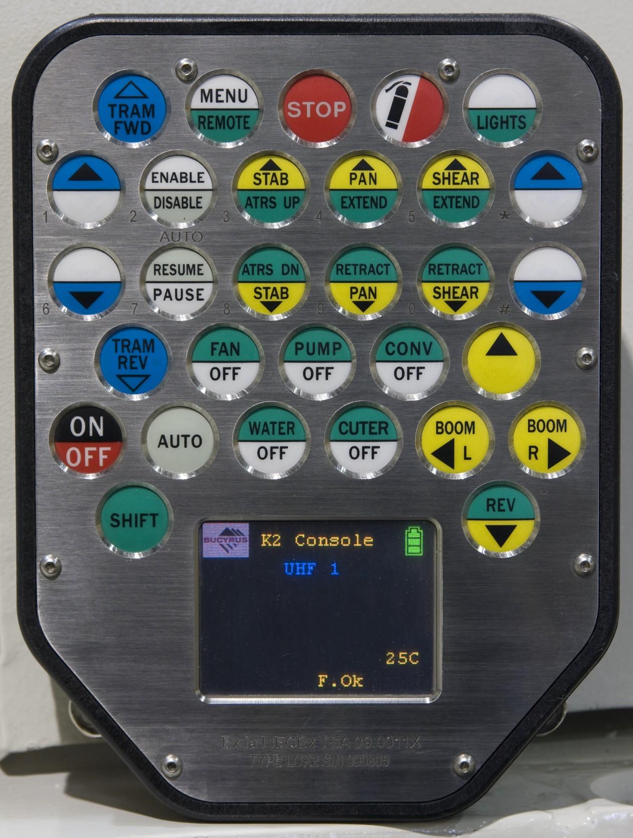
Radio Remote
The radio remote (Fig. 1) is used to control the continuous miner during normal mining operations.
Radio remote control systems are dangerous. The continuous miner operator cannot operate a remote system until he is properly trained in the operation of the system. Remote control systems sometimes have automatic features of which untrained operators and workers may not be aware. WARNING
Displays
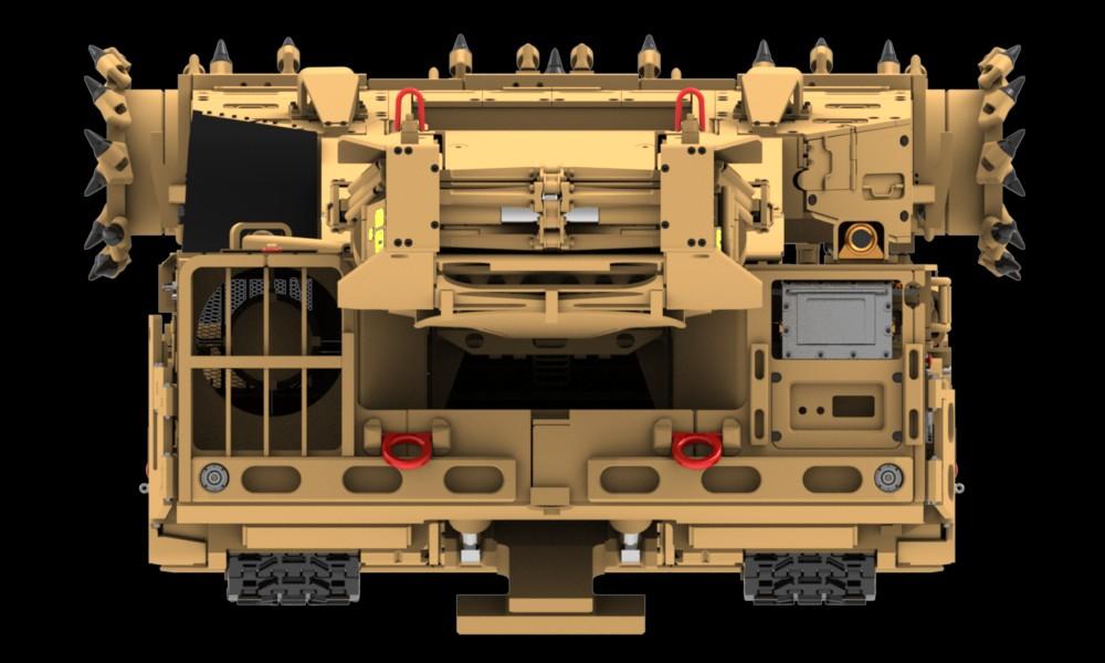
There are two displays located on the machine: a graphics display located at the operator’s case and a text display located near the back right hand side of the machine (Fig. 2). Both screens are used to display diagnostic information on the miner.
Fig. 2: Control system display location (typical)
Displays
Graphics display
Information priority is given to the graphics display unless the graphics display becomes unhealthy. The two monitors will not necessarily display the same information at the same time.
The graphics display, generally located on the rear bumper of the machine, is used to monitor machine operating parameters, for diagnosing error and fault codes, and for input of operating parameters.
The text display, located on the rear right bumper of the machine, has the same functions as the graphics display. If the control system loses power, the text display will remain powered through the battery back up.
There are different screens that can be displayed: production monitoring, function monitoring, diagnostic, motor hours, and fault pages. A system halt message can appear as a pop-up dialog box in the middle of any screen. A message will appear when a critical conditions has occurred that prevents continued operation of the machine in a safe manner. The message box cannot be cleared and it is necessary to recycle power to the control system to restore machine operation.
The LED display (Fig. 3), located on the rear bumper, gives pictorial representation of the following situations:
■ E-Stop
■ Methane Trip
■ Water Trip
■ Key Switch Off
■ Motor Overload Trip
■ Low Oil Trip
■ Radio Signal Loss
■ Earth Leakage
■ Low Oil Warning
■ Scrubber Filter Blocked
■ Boom Lower Limit
■ Boom Upper Limit
■ No Fault
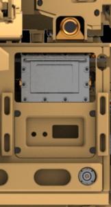
Fig. 4 shows some examples of the typical displays.
Fig. 4: Typical LED displays
Boom lower limit

Operator key switch off
Water trip
Emergency stop
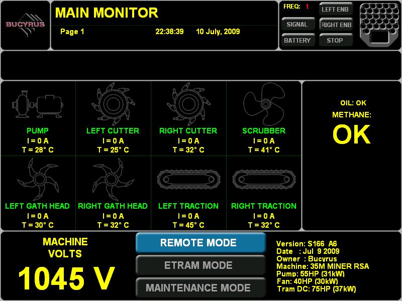
When the system is turned on, the main page (Fig. 5) is displayed. The operator can toggle between three (3) different types of screens in normal operation mode: the main page, the production monitor, and the individual monitor pages (boom, pump, scrubber, cutters, and gathering head. To page left, press [SHIFT] and “CONV LEFT” on the radio remote. To page right, press [SHIFT] and “CONV RIGHT” on the radio remote.
The main page consists of an alarm banner, methane status, oil level status, and input current and temperature readings from the pump, left and right cutter motors, scrubber motor, left and right gathering head motors, and left and right traction motors. It also display voltage on the machine and mode of operation (remote, etram, or maintenance).
A status message is typically only displayed on the main page. It is a brief text description of a event or function that is currently active. A status message is typically not used to indicate any fault or warning condition and are not numbered.

Radio remote information
Mode of operation
System Menu
The system menu (Fig. 6) allows access to different functions of the control system.
Fig. 6: System menu
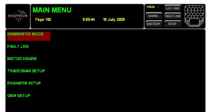
Diagnostic mode
Using the radio remote:
1. To enter the system menu screen, press the [MENU] key.
2. To move the cursor, press the CONV LEFT or CONV RIGHT key.
3. To select an option, press the [MENU] key.
4. To exit or go back, press the TRAM FORWARD key.
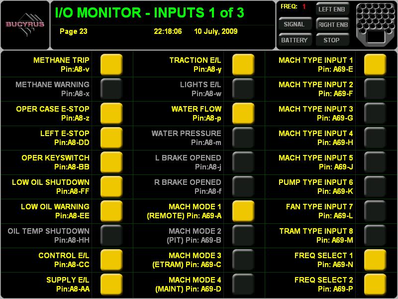
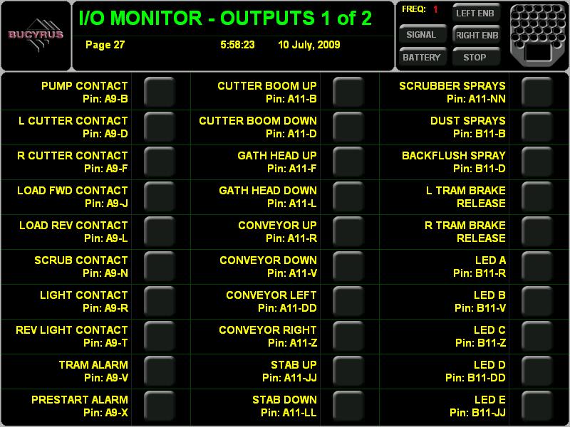
Diagnostic mode allows a large number of monitoring screens to be displayed and selected while the machine is operating and includes the following pages:
■ Main monitor page
■ Production monitor page
■ Boom monitor page
■ Pump Monitor page
■ Scrubber monitor page
■ Cutters monitor page
■ Gathering head monitor page
■ Traction motor monitor page
■ I/O monitor pages - three (3) inputs pages
■ I/O monitor pages - two (2) outputs pages
■ Network monitor page
■ RMS drive monitor page
See Fig. 7 for examples of various diagnostic pages.
Fault Log
The fault log (Fig. 8) stores the last one hundred (100) faults that have occurred on the machine. The faults are stored in a First In First Out basis (as a new fault is added, the oldest fault is deleted). Each possible fault event is identified by a unique number. Individual faults can be selected to view more detail.
To select a fault from the fault log, from the radio remote:
1. To move the cursor up, press the CONV UP key.
2. To move the cursor down, press the CONV DOWN key.
3. To move up one page, press the [SHIFT] and CONV UP keys.
4. To move down one page, press the [SHIFT] and CONV DOWN keys.
5. To select a fault, press the [MENU] key.
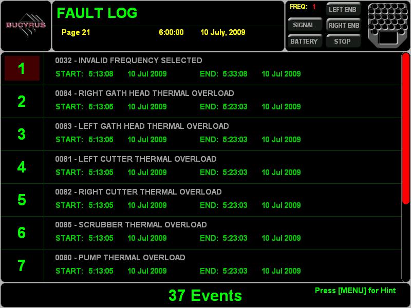
An error message is used by the control system to indicated warning conditions that are currently active but do not necessarily shutdown machine operation. Error messages are set and cleared by the control system automatically in response to real-time system background monitoring. Error messages are typically only visible during normal machine operation on the main page of the control system graphic display screen. Error messages are numbered and use number less than 200.
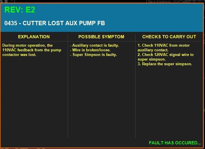
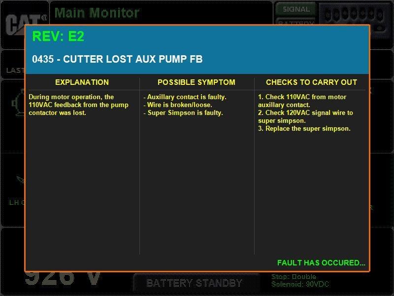
A fault message is a condition that shuts down a motor or function or that prevents a function from being started. When a fault is detected, a fault screen (Fig. 9) will display over top of the current monitoring screen. The fault message, explaining what is keeping the machine from running, will be displayed. The operator must clear the fault by pressing [SHIFT] and RESUME on the radio remote unless the system is set to Auto Fault Clear. If the system is set to Auto Fault Clear, the fault is automatically cleared by the next key press.
Fault messages are logged in the control system fault log and are number using numbers greater than 200.
For a complete list of error and fault codes, please see the Troubleshooting Guide.
Fig. 9: Individual fault detail

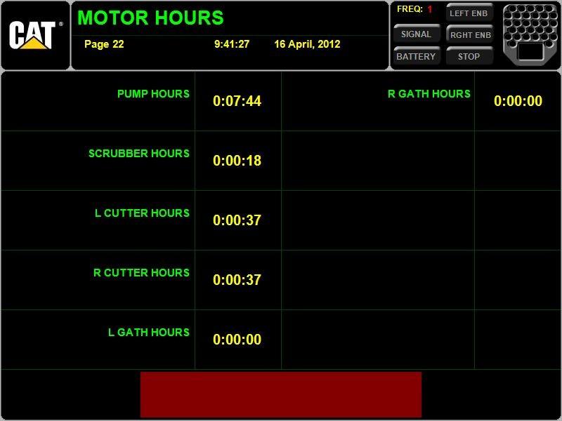
The motor hours screen (Fig. 10) allows the running time for all hour meters to be viewed. Hour meters are stored in the processor’s non-volatile memory (NVRAM). If the processor is changed, the correct motor hours must be configured into the system.
The control system provides three levels of access to machine configuration parameters: Tradesman, Engineer, and OEM. Each level has its own password that must be entered in order to view or change parameters.
Tradesman Setup
Engineer Setup
The following parameters are available from the Tradesman Setup screen with the Tradesmen password:
1. Test Menu
a. Solenoid test page
b. Console test page
2. Inclinometer Menu
a. Boom inclinometer enable/disable
b. Body inclinometer enable/disable
c. Inclinometer roof limits
1. Cutter in coal
2. Roof limit
3. Top air overshoot
4. Top cutting overshoot
5. Floor limit
6. Bottom air overshoot
7. Bottom cutting overshoot
The following parameters are available from the Engineer Setup screen with the Engineer password:
1. Test Menu - Same as Tradesman
2. Inclinometer Menu
a. Zero boom height
b. Boom inclinometer enable/disable
c. Body inclinometer enable/disable
d. Boom raw milliamps percentage
e. Geometry Settings
1. Boom length
2. Boom pivot height
3. Cutter drum radius
f. Inclinometer roof limits
1. Cutter in coal
2. Roof limit
3. Top air overshoot
4. Top cutting overshoot
5. Floor limit
6. Bottom air overshoot
7. Bottom cutting overshoot
3. Clear Motor Hours Page
4. Data Logging
a. Data logging enabled
b. Data logging baud rate
c. Data logging refresh rate
5. Machine Config Menu
a. Fan/cutter menu
1. Fan/cutter mode - fan first/cutter first/either
2. Fan/cutter stagger delay
3. Fan auto off delay
4. Cutter ratchet start timer
5. Cutter water flow delay
6. Blocked scrubber detection enabled
7. Blocked scrubber filter
8. Back flush spray
9. Back flush spray time
10. Back flush cycle time
b. Interlock Menu
1. Oil level shutdown
2. Oil level warning
3. Water flow
c. Verbose Fault Alert
d. Module Diagnostic Mode
e. EStop trip
f. Machine voltage max
g. Machine voltage min
h. Machine voltage brownout
i. Brake release delay
j. Auto fault clear
6. RTD Settings
a. Enable RTD monitoring
b. Enable pump RTD
c. Enable left cutter RTD
d. Enable right cutter RTD
e. Enable scrubber RTD
f. Enable left conveyor RTD
g. Enable right conveyor RTD
h. Enable tram transformer RTD
i. Enable left tram RTD
j. Enable right tram RTD
7. Offline Checks
a. Methane warning
b. Operator key switch
c. Oil shutdown
d. Oil warning
e. Control earth leakage
f. Supply earth leakage
g. Traction earth leakage
h. Water flow
8. Pre-Start Timers
a. Pump
b. Scrubber
c. Cutters
d. Conveyors
e. Mode change
9. Motor Config
a. Motor full load current settings (viewing only)
1. Pump
2. Scrubber
3. Cutter
4. Conveyor
5. Traction
b. Shear max cutter current
c. Shear min cutter current
d. Motor trip timers
1. Cutter imbalance run-time
2. Cutter imbalance startup
3. Traction undercurrent time
4. Traction illegal current time
10. Traction Config
a. Left hand trim
b. Right hand trim
c. Sump settings
1. Max cutter current
2. Min cutter current
3. Sump speed delta
4. Left hand max sump speed
5. Right hand max sump speed
6. Left hand min sump speed
7. Right hand min sump speed
d. Left tram speeds
1. Speed 1
2. Speed 2
3. Speed 3
e. Right tram speeds
1. Speed 1
2. Speed 2
3. Speed 3
f. Tram start delay
11. Auto Stab Config
a. Auto stab enable
b. Auto stab in coal seam current
c. Auto stab down timer
12. Password Setup
a. Tradesman Password
13. Date/Time Config
14. Clear Fault Log Page
15. Reset Defaults Page