Pages 001 0100 Massey Ferguson 200 300 cc Agtv Model Service & Maintenance Manual
Table of Contents
CLICK HERE TO DOWNLOAD THE COMPLETE MANUAL
• Thank you very much for reading the preview of the manual.
• You can download the complete manual from: www.heydownloads.com by clicking the link below
• Please note: If there is no response to CLICKING the link, please download this PDF first and then click on it.
CLICK HERE TO DOWNLOAD THE
General Information
SPECIFICATIONS 250/300 CC
This manual contains service, maintenance, and troubleshooting information for the 2001 MASSEY FERGUSON AgTV models. The manual is designed to aid service personnel in service-oriented applications and may be used as a textbook for service training.
This manual is divided into sections. Each section covers a specific AgTV component or system and, in addition to the standard service procedures, includes disassembling, inspecting, and assembling instructions. When using this manual as a guide, the technician should use discretion as to how much disassembly is needed to correct any given condition. A troubleshooting section is also included in this manual.
The service technician should become familiar with the operation and construction of each component or system by carefully studying this manual. This manual will assist the service technician in becoming more aware of and efficient with servicing procedures. Such efficiency not only helps build consumer confidence but also saves time and labour.
All MASSEY FERGUSON AgTV publications and decals display the words Warning, Caution andNote, to emphasise important information. The symbol WARNING identifies personal safety-related information. Be sure to follow the directive because it deals with the possibility of severe personal injury or even death. The symbol CAUTION identifies unsafe practices which may result in AgTV-related damage. Follow the directive because it deals with the possibility of damaging part or parts of the AgTV. The symbol NOTE identifies supplementary information worthy of particular attention. At the time of publication, all information, photographs, and illustrations were technically correct. Some photographs used in this manual are used for clarity purposes only and are not designed to depict actual conditions. MASSEY FERGUSON constantly refines and improves its products, no retroactive obligation is incurred.
All materials and specifications are subject to change without notice.
Keep this manual accessible in the shop area for reference.
VALVES AND GUIDES
Valve Face Diameter (intake)33 mm (1.3 in.) (exhaust)28 mm (1.1 in.)
Valve/Tappet Clearance (cold engine) (intake)0.03-0.08 mm (0.001-0.003 in.) (exhaust)0.08-0.13 mm (0.003-0.005 in.)
ValveGuide/Stem Clearance (intake)0.010-0.037 mm (0.0004-0.0015 in.) (exhaust)0.030-0.057 mm (0.0012-0.0024 in.)
ValveGuide/ValveStem Deflection Wobble method (max)0.35 mm (0.014 in.)
Valve Guide Inside Diameter5.500-5.512 mm (0.2165-0.2170 in.)
ValveStemOutside Diameter (intake)5.475-5.490 mm (0.2156-0.2161 in.) (exhaust) 5.455-5.470 mm (0.2148-0.2154 in.)
Valve Stem Runout (max)0.05 mm (0.002 in.)
ValveHead Thickness (max)0.5 mm (0.02 in.)
Valve Stem End Length (max)2.7 mm (0.11 in.)
Valve Face/Seat Width0.9-1.1 mm (0.035-0.043 in.)
Valve Seat Angle (intake)45° (exhaust)45°
Valve Face Radial Runout (max)0.03 mm (0.001 in.)
Valve Spring Free Length (max) (inner)35.1 mm (1.38 in.) (outer)39.9 mm (1.57 in.)
Valve Spring Tension @ 32.5 mm (1.28 in.) (inner)7.1-9.2 kg (15.7-20.3 lb.)
Valve Spring Tension @ 36.0 mm (1.42 in.) (outer)17.3-21.3 kg (38.1-47.0 lb.)
CAMSHAFT AND CYLINDER HEAD
Cam Lobe Height (min.) (intake)33.820 mm (1.331 in.) (exhaust)33.490 mm (1.318 in.)
Camshaft Journal Oil Clearance (max)0.15 mm (0.0059 in.)
CamshaftJournal HolderInside Diameter22.012-22.025 mm (0.8666-0.8671 in.)
* Specifications subject to change without notice.
BREAK-IN PROCEDURE
A new AgTV and an overhauled AgTV engine require a break-in period. The first 10 hours (or 200 miles) are most critical to the life of this AgTV. Proper operation during this break-in period will help assure maximum life and performance from the AgTV.
During the first 10 hours (or 200 miles) of operation, always use less than 1/2 throttle. Varying the engine RPM during the break-in period allows the components to “load” (aiding the mating process) and then “unload” (allowing components to cool). Although it is essential to place some stress on the engine components during break-in, care should be taken not to overload the engine too often. Do not pull a trailer or carry heavy loads during the 10-hour break-in period.
When the engine starts, allow it to warm up properly. Idle the engine several minutes until the engine has reached normal operating temperature. Do not idle the engine for excessively long periods of time.
During the break-in period, a maximum of 1/2 throttle is recommended; however, brief full-throttle accelerations and variations in driving speeds contribute to good engine break-in.
During the break-in period (or whenever the brake pads are replaced), the hydraulic brake pads must be burnished. Slow disc-speed hydraulic brakes must be properly burnished in order to achieve maximum stopping power.
CAUTION: Brake pads must be burnished to achieve full braking effectiveness. Braking distance will be extended until brake pads are properly burnished.
To properly burnish the brakes, use following procedure:
• Choose an area sufficiently large to safely accelerate AgTV to 30 mph and to brake to a stop.
• Using third gear, accelerate to 30 mph; then compress brake lever to decelerate to 0-5 mph.
• Repeat procedure 20 times until brakes are burnished.
• This procedure burnishes the brake pads, stabilizes the pad material, and extends the life of the brake pads.
WARNING: Do not attempt sudden stops or put the AgTV into a situation where a sudden stop will be required until the brake pads are properly burnished.
NOTE: Do not be reluctant to heat up the brake pads during the burnishing procedure.
NOTE: After the completion of the break-in period, the engine oil and oil filter should be changed. Other maintenance after break-in should include checking of all prescribed adjustments and tightening of all fasteners.
PETROL-OIL-LUBRICANT
Recommended fuel
The recommended petrol to use in this AgTV is 87 minimum octane regular unleaded. In many areas, oxygenates (either ethanol or MTBE) are added to the petrol. Oxygenated petrol containing up to 10% ethanol, 5% methane, or 5% MTBE are acceptable petrols. When using ethanol blended petrol, it is not necessary to add a petrol antifreeze since ethanol will prevent the accumulation of moisture in the fuel system.
Recommended engine/transmission oil
CAUTION: Any oil used in place of the recommended oil could cause serious engine damage. Do not use oils which contain graphite or molybdenum additives. These oils can adversely affect clutch operation. Also, not recommended are racing, vegetable, non-detergent, and castor-based oils.
The recommended oil to use in this AgTV is MASSEY FERGUSON Engine Oil SAE 10W/40 (ATV0436-005) or an equivalent oil which is rated SE, SF, or SG under API service classification. These oils meet all of the lubrication requirements of the MASSEY FERGUSON AgTV engine. The recommended engine oil viscosity is SAE 10W-40. Ambient temperature should determine the correct weight of oil. See the viscosity chart for details, (Fig. 1).
Fig. 1
General Information
Recommended front differential/rear drive lubricant
The recommended lubricant is MASSEY FERGUSON (ATV0436-007) or an equivalent gear lube which is SAE approved 80W-90 hypoid. This lubricant meets all of the lubrication requirements of the MASSEY FERGUSON AgTV differentials.
CAUTION: Any lubricant used in place of the recommended lubricant could cause serious front differential/rear drive damage.
Filling petrol tank
WARNING: Always fill the petrol tank in a wellventilated area. Never add fuel to the AgTV petrol tank near any open flames or with the engine running. DO NOT SMOKE while filling the petrol tank, (Fig.2).
Since petrol expands as its temperature rises, the petrol tank must be filled to its rated capacity only. Expansion room must be maintained in the tank particularly if the tank is filled with cold petrol and then moved to a warm area.
WARNING: Do not over-flow petrol when filling the petrol tank. A fire hazard could materialise. Always allow the engine to cool before filling the petrol tank. Tighten the petrol tank cap securely after filling the tank.
WARNING: Do not over-fill the petrol tank.
GENUINE PARTS
When replacement of parts is necessary, use only genuine MASSEY FERGUSON AgTV parts. They are precision-made to ensure high quality and correct fit. Refer to the appropriate Illustrated Parts Manual for the correct part number, quantity, and description.
Fig.2
General
LOAD CAPACITY RATINGS CHARTS
MASSEY FERGUSON Load capacity ratings 250/300 cc
ItemSpecifications (lb)(Kg)*
Max load capacity1050477
Calculation
Operator20091
Front rack (max)7534
Rear rack (max)15068
Accessories (i.e, winch, gun brackets, etc) 3515
Maximum AgTV load capacity (w/ trailer & cargo) 1050477
* Rounded off
PREPARATION FOR STORAGE
CAUTION: Prior to storing the AgTV, it must be properly serviced to prevent rusting and component deterioration. MASSEY FERGUSON recommends the following procedure to prepare the AgTV for storage.
1.Clean the seat cushion with a damp cloth and allow it to dry.
2.Clean the AgTV thoroughly by hosing dirt, oil, grass, and other foreign matter from the entire AgTV. Allow the AgTV to dry thoroughly. DO NOT get water into any part of the engine.
3.Either drain the petrol tank or add Fuel Stabilistyreer (AgTV 0638-165) to the petrol in the tank. Remove the air cleaner cover and air filter. Start the engine and allow it to idle; then using MASSEY FERGUSON Engine Storage Preserver (ATV 0636-177), rapidly inject the preserver into the air filter opening for a period of 10 to 20 seconds; then stop the engine. Install the air filter and cover.
4.Plug the exhaust hole in the muffler with a clean cloth.
5.Apply light oil to the upper steering post bushing, plungers of the shock absorbers, and cable ends.
6.Tighten all nuts, cap screws, and screws. Make sure rivets holding components together are tight. Replace all loose rivets. Care must be taken that all calibrated nuts, cap screws, and screws are tightened to specifications.
7.On liquid cooled models, fill the cooling system to 1/2 in. above the radiator core with properly mixed coolant.
8.Polish the AgTV thoroughly.
9.Disconnect the battery cables; then clean the battery posts and cables. Remove the battery and store in a clean, dry area.
10.Store the AgTV indoors in a level position.
CAUTION: Avoid storing outside in direct sunlight and avoid using a plastic cover as moisture will collect on the AgTV causing rusting.
PREPARATION AFTER STORAGE
Taking the AgTV out of storage and correctly preparing it will assure many miles and hours of trouble-free riding. MASSEY FERGUSON recommends the following procedure to prepare the AgTV.
1.Clean the AgTV thoroughly.
2.Clean the engine. Remove the cloth from the muffler.
3.Check all control wires and cables for signs of wear or fraying. Replace if necessary.
4.Change the engine/transmission oil and filter and the front differential/rear drive lubricant.
5.On liquid cooled models, check the coolant level and add properly mixed coolant as necessary.
6.Charge the battery; then install. Connect the battery cables; then coat the terminals with grease.
7.Check the entire brake systems (fluid level, pads, etc.), all controls, headlight, taillight, brakelight, and headlight aim; adjust or replace as necessary.
8.Tighten all nuts, cap screws, and screws making sure all calibrated nuts, cap screws, and screws are tightened to specifications.
9.Make sure the steering moves freely and does not bind.
10.Check the spark plug. Clean or replace as necessary.
11.Inspect the air filter and air cleaner housing for obstructions.
12.Check and inflate tyres to recommended pressure.
General Information
Page left blank intentionally
General Information
General Information
Table of Contents
General Information
SPECIFICATIONS*(400 CC)
VALVES AND GUIDES
Valve face diameter (intake)30.6 mm (1.20 in.) (exhaust)27.0 mm (1.06 in.)
Valve/tappet clearance (cold engine) (intake)0.05-0.10 mm (0.002-0.004 in.) (exhaust)0.17-0.22 mm (0.007-0.009 in.)
Valve guide/Stem clearance (intake)0.010-0.037 mm (0.0004-0.0015 in.) (exhaust)0.030-0.057 mm (0.0012-0.0022 in.)
Valveguide valvestemdeflection(wobblemethod)(max) 0.35 mm (0.014 in.)
Valve guide inside diameter5.000-5.012 mm (0.1969-0.1973 in.)
Valve stem outside diameter (intake)4.975-4.990 mm (0.1959-0.1965 in.) (exhaust)4.955-4.970 mm (0.1951-0.1957 in.)
Valve stem runout (max)0.05 mm (0.002 in.)
Valveheadthickness (max)0.5 mm (0.02 in.)
Valvestemend length (max)1.8 mm (0.07 in.)
Valve face/Seat width 0.9-1.1 mm (0.035-0.043 in.)
Valve seat angle (intake)45° (exhaust)45°
Valve face radial runout (max)0.03 mm (0.001 in.)
Valve spring free Length (max) (inner)35 mm (1.38 in.) (outer)37.8 mm (1.49 in.)
Valve spring tension @ 28 mm (1.10 in.) (inner) 5.3-6.5 kg (11.7-14.3 lb.)
Valve spring tension @ 31.5 mm (1.24 in.) (outer)13.1-15.1 kg (28.9-33.3 lb.)
CLICK HERE TO DOWNLOAD THE COMPLETE MANUAL
• Thank you very much for reading the preview of the manual.
• You can download the complete manual from: www.heydownloads.com by clicking the link below
• Please note: If there is no response to CLICKING the link, please download this PDF first and then click on it.
CLICK HERE TO DOWNLOAD THE
CAMSHAFT AND CYLINDER HEAD
Cam lobe height (min.)
(intake)33.150 mm (1.305 in.) (exhaust)33.220 mm (1.308 in.)
Camshaft journal oil clearance (max)0.15 mm (0.0059 in.)
Camshaftjournal holderinside diameter
(right and centre)21.959-21.980 mm (0.8645-0.8654 in.) (left)17.512-17.525 mm (0.6894-0.6900 in.)
Camshaft journal outside diameter (right and centre)21.959-21.980 mm (0.8645-0.8654 in.)
(left)7.465-17.484 mm (0.6876-0.6883 in.)
Camshaft runout (max)0.10 mm (0.004 in.)
Rockerarminside diameter12.000-12.018 mm (0.472-0.473 in.)
Rockerarmshaft outside diameter11.973-11.984 mm (0.4714-0.4718 in.)
Cylinder head distortion (max)0.05 mm (0.002 in.)
Cylinderheadcoverdistortion (max)0.05 mm (0.002 in.)
CYLINDER,PISTON AND RINGS
Piston skirt/Cylinder clearance0.045-0.120 mm (0.0018-0.0047 in.)
Cylinder bore84.000-84.085 mm (3.3071-3.3104 in.)
Pistondiameter 15mm(0.6in.)from Skirt End83.880-83.965 mm (3.3024-3.3057 in.)
Piston ring freeendgap (approx.) (1st Ring)8.4-10.5 mm (0.33-0.41 in.) (2nd Ring)9.5-11.8 mm (0.37-0.46 in.)
Bore x Stroke84 x 67 mm (3.30 x 2.64 in.)
Cylinder trueness (max)0.05 mm (0.002 in.)
Ring end gap (max)0.50 mm (0.020 in.)
Piston ring to groove clearance (max)
(1st)0.180 mm (0.0071 in.) (2nd)0.150 mm (0.0059 in.)
A new AgTV and an overhauled AgTV engine require a break-in period. The first 10 hours (or 200 miles) are most critical to the life of this AgTV. Proper operation during this break-in period will help assure maximum life and performance from the AgTV.
During the first 10 hours (or 200 miles) of operation, always use less than 1/2 throttle. Varying the engine RPM during the break-in period allows the components to “load” (aiding the mating process) and then “unload” (allowing components to cool). Although it is essential to place some stress on the engine components during break-in, care should be taken not to overload the engine too often. Do not pull a trailer or carry heavy loads during the 10-hour break-in period.
When the engine starts, allow it to warm up properly. Idle the engine several minutes until the engine has reached normal operating temperature. Do not idle the engine for excessively long periods of time.
During the break-in period, a maximum of 1/2 throttle is recommended; however, brief full-throttle accelerations and variations in driving speeds contribute to good engine break-in.
During the break-in period (or whenever the brake pads are replaced), the hydraulic brake pads must be burnished. Slow disc-speed hydraulic brakes must be properly burnished in order to achieve maximum stopping power.
CAUTION: Brake pads must be burnished to achieve full braking effectiveness.Braking distance will be extended until brake pads are properly burnished.
To properly burnish the brakes, use following procedure:
• Choose an area sufficiently large to safely accelerate AgTV to 30 mph and to brake to a stop.
• Using third gear, accelerate to 30 mph; then compress brake lever to decelerate to 0-5 mph.
• Repeat procedure 20 times until brakes are burnished.
• This procedure burnishes the brake pads, stabilises the pad material, and extends the life of the brake pads.
WARNING: Do not attempt sudden stops or put the AgTV into a situation where a sudden stop will be required until the brake pads are properly burnished.
NOTE: Do not be reluctant to heat up the brake pads during the burnishing procedure.
1
NOTE: After the completion of the break-in period, the engine oil and oil filter should be changed. Other maintenance after break-in should include checking of all prescribed adjustments and tightening of all fasteners.
PETROL-OIL-LUBRICANT
Recommended petrol
The recommended petrol to use in this AgTV is 87 minimum octane regular unleaded. In many areas, oxygenates (either ethanol or MTBE) are added to the petrol. Oxygenated petrols containing up to 10% ethanol, 5% methane, or 5% MTBE are acceptable petrols. When using ethanol blended petrol, it is not necessary to add a petrol antifreeze since ethanol will prevent the accumulation of moisture in the fuel system.
Recommended engine/transmission oil
CAUTION: Any oil used in place of the recommended oil could cause serious engine damage. Do not use oils which contain graphite or molybdenum additives. These oils can adversely affect clutch operation. Also, not recommended are racing, vegetable, non-detergent, and castor-based oils.
The recommended oil to use in this AgTV is MASSEY FERGUSON Engine Oil SAE 10W/40 (ATV0436-005) or an equivalent oil which is rated SE, SF, or SG under API service classification. These oils meet all of the lubrication requirements of the MASSEY FERGUSON AgTV engine. The recommended engine oil viscosity is SAE 10W-40. Ambient temperature should determine the correct weight of oil. See the viscosity chart for details, (Fig. 1).
Fig.
Recommended front differential/rear drive lubricant
The recommended lubricant is MASSEY FERGUSON (ATV0436-007) or an equivalent gear lube which is SAE approved 80W-90 hypoid. This lubricant meets all of the lubrication requirements of the MASSEY FERGUSON AgTV differentials.
CAUTION: Any lubricant used in place of the recommended lubricant could cause serious front differential/rear drive damage.
Filling petrol tank
WARNING: Always fill the petrol tank in a wellventilated area. Never add fuel to the AgTV petrol tank near any open flames or with the engine running. DO NOT SMOKE while filling the petrol tank.
Since petrol expands as its temperature rises, the petrol tank must be filled to its rated capacity only, (Fig.2). Expansion room must be maintained in the tank particularly if the tank is filled with cold petrol and then moved to a warm area.
WARNING: Do not over-flow petrol when filling the petrol tank. A fire hazard could materialise. Always allow the engine to cool before filling the petrol tank. Tighten the petrol tank cap securely after filling the tank.
WARNING: Do not over-fill the petrol tank.
GENUINE PARTS
When replacement of parts is necessary, use only genuine MASSEY FERGUSON AgTV parts. They are precision-made to ensure high quality and correct fit. Refer to the appropriate Illustrated Parts Manual for the correct part number, quantity, and description.
Maximum AgTV load capacity (w/trailer & cargo) 12505681220554
* Rounded off
**For the 400 cc only; there is no 500cc 2x4 model
PREPARATION FOR STORAGE
CAUTION: Prior to storing the AgTV, it must be properly serviced to prevent rusting and component deterioration. MASSEY FERGUSON recommends the following procedure to prepare the AgTV for storage.
1.Clean the seat cushion with a damp cloth and allow it to dry.
2.Clean the AgTV thoroughly by hosing dirt, oil, grass, and other foreign matter from the entire AgTV. Allow the AgTV to dry thoroughly. DO NOT get water into any part of the engine.
3.Either drain the petrol tank or add Fuel Stabiliser (ATV 0638-165) to the petrol in tank. Remove the air cleaner cover and air filter. Start the engine and allow it to idle; then using MASSEY FERGUSON Engine Storage Preserver (ATV 0636-177), rapidly inject the preserver into the air filter opening for a period of 10 to 20 seconds; then stop the engine. Install the air filter and cover.
4.Plug the exhaust hole in the muffler with a clean cloth.
5.Apply light oil to the upper steering post bushing, plungers of the shock absorbers, and cable ends.
6.Tighten all nuts, cap screws, and screws. Make sure rivets holding components together are tight. Replace all loose rivets. Care must be taken that all calibrated nuts, cap screws, and screws are tightened to specifications.
7.On liquid cooled models, fill the cooling system to 1/2 in. above the radiator core with properly mixed coolant.
8.Polish the AgTV thoroughly.
9.Disconnect the battery cables; then clean the battery posts and cables. Remove the battery and store in a clean, dry area.
10.Store the AgTV indoors in a level position.
CAUTION: Avoid storing outside in direct sunlight and avoid using a plastic cover as moisture will collect on the AgTV causing rusting.
PREPARATION AFTER STORAGE
Taking the AgTV out of storage and correctly preparing it will assure many miles and hours of trouble-free riding.
MASSEYFERGUSONrecommendsthefollowing procedure to prepare the AgTV.
1.Clean the AgTV thoroughly.
2.Clean the engine. Remove the cloth from the muffler.
3.Check all control wires and cables for signs of wear or fraying. Replace if necessary.
4.Change the engine/transmission oil and filter and the front differential/rear drive lubricant.
5.On liquid cooled models, check the coolant level and add properly mixed coolant as necessary.
6.Charge the battery; then install. Connect the battery cables; then coat the terminals with grease.
7.Check the entire brake systems (fluid level, pads, etc.), all controls, headlight, taillight, brakelight, and headlight aim; adjust or replace as necessary.
8.Tighten all nuts, cap screws, and screws making sure all calibrated nuts, cap screws, and screws are tightened to specifications.
9.Make sure the steering moves freely and does not bind.
10.Check the spark plug. Clean or replace as necessary.
11.Inspect the air filter and air cleaner housing for obstructions.
12.Check and inflate tyres to recommended pressure.
CLICK HERE TO DOWNLOAD THE COMPLETE MANUAL
• Thank you very much for reading the preview of the manual.
• You can download the complete manual from: www.heydownloads.com by clicking the link below
• Please note: If there is no response to CLICKING the link, please download this PDF first and then click on it.
CLICK HERE TO DOWNLOAD THE
Maintenance
Section 2-A 250/300
Table of Contents
PERIODIC
MAINTENANCE CHART
A = AdjustI = Inspect
C = CleanL = Lubricate
D = DrainR = Replace
ItemInitial service after breakin(First monthor 200 miles)
Air filter/Drain tube
Valve/tappet clearance
Muffler/spark arrester
hoses
Steering components
Front axle
Boots/ driveshaft Universal joint
Suspension/ shock absorbers/ bushings
Nuts/cap screws/ screws
Ignition timing
Headlight/ taillightbrakelight
Switches
Frame/Welds/ Racks
Electrical connections
Complete brake system (Hydraulic & Mechanical)
Brake padsII*R
Brake fluid IIR (2yrs)
Brake hosesII R (4 yrs.)
Coolant/ Cooling system IIR (2 yrs.)
Upper arm/ knuckle (rear)
* Service/Inspect more frequently when operating in adverse conditions.
** If a rear arm grease fitting does not accept grease, do not force grease into fitting.
LUBRICATION POINTS
It is advisable to lubricate certain components periodically to ensure free movement. Apply light oil to the components using the following list as reference.
A -Throttle Lever Pivot/Cable Ends.
B - Brake Lever Pivot/Cable Ends.
C - Mechanical Brake Cable Ends.
D - Choke Cable Upper End.
E - Reverse Lever Cable End
F - Idle RPM Screw (carburettor)
G - Upper/Lower Rear Arms (6 Locations - 250/300 cc)
NOTE: If a rear arm grease fitting does not accept grease, do not force grease into the fitting.
Maintenance
BATTERY
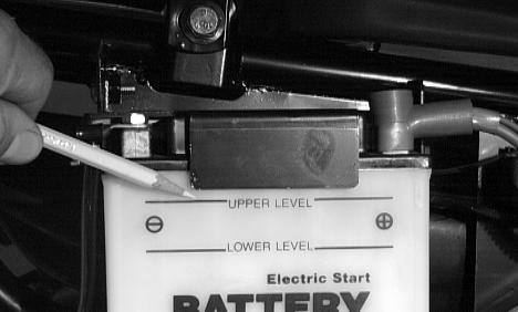
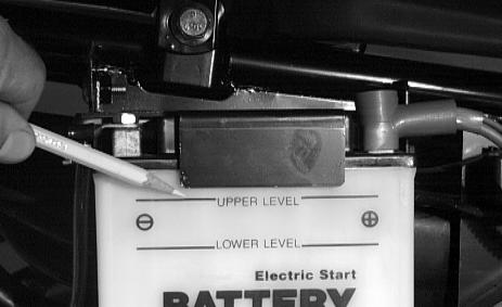
The battery is located under the right rear fender. The level of the battery fluid must be kept between the upper and lower level lines at all times. If the level drops below the lower level line, add only distilled water until it reaches upper level line.
WARNING: Battery acid is harmful if it contacts eyes, skin, or clothing. Care must be taken whenever handling a battery.
If the battery is discharged, remove the battery from the AgTV and charge the battery at the standard charging rate of 1.4A x 10 hr.
WARNING: Anytime service is performed on a battery, the following must be observed: keep sparks, open flame, cigarettes, or any other flame away. Always wear safety glasses. Protect skin and clothing when handling a battery. When servicing battery in enclosed space, keep the area well-ventilated. Make sure battery venting is not obstructed.
To remove and charge the battery, use the following procedure;
1.Remove the battery hold-down bracket.
2.Remove the negative battery cable; then remove the positive cable and the battery vent tube. Remove the battery from the AgTV. Care should be taken not to damage the vent tube.
WARNING: Avoid spillage and contact with skin, eyes, and clothing.
CAUTION: Do not charge the battery while it is in the AgTV with the battery terminals connected.
3.Remove the vent plugs; then (if necessary) fill the battery with distilled water to the upper level indicated on the battery.
4.Trickle charge the battery at 1.4 amps for 10 hours.
CAUTION: Never exceed the standard charging rate.
5.After charging, check fluid level and fill with distilled water as necessary; then install vent plugs.
CAUTION: Before installing the battery, make sure the ignition switch is in the OFF position.
Fig. 1
Fig.2
Fig.3
6. Place the battery into position in the AgTV and secure with the hold-down bracket.
7.Attach the vent tube and check the vent tube to make sure it is not crimped or obstructed in any way and that it is properly routed through and secured to the frame.
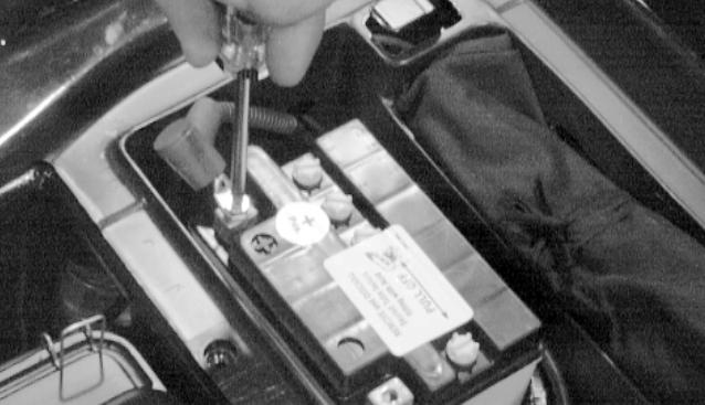
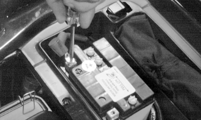
8.Connect cables to the proper terminals: positive cable to the positive terminal (+) and negative cable to the negative terminal (-). Connect the negative cable last, (Fig.4).
CAUTION: Connecting cables in reverse (positive to negative and negative to positive) can cause serious damage to the electrical system.
FUSES
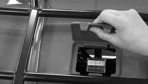
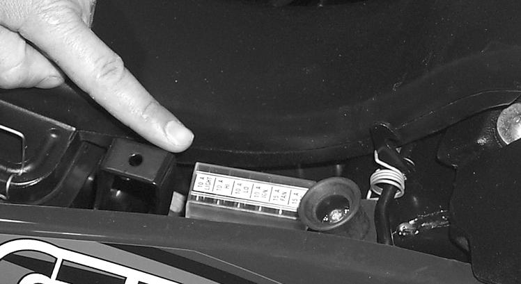
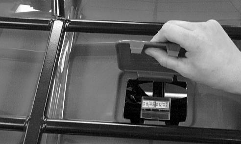
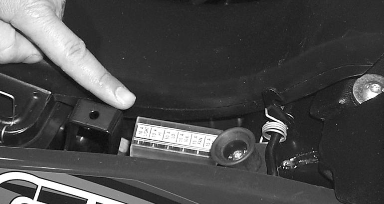
On the 250/300 cc, the fuses are located in the centre of the front fender beneath a snap-on cover, (Fig.5).
NOTE: To remove the fuse, compress the locking tabs on either side of the fuse case and lift out.
CAUTION: Always replace a blown fuse with a fuse of the same type and rating.
Fig.4
Fig.5
Fig.6
Maintenance
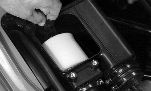
AIR CLEANER
The two-part air filter inside the air cleaner must be kept clean to provide good engine power and petrol mileage. If the AgTV is used under normal conditions, service the filter at the intervals specified. If operated in dusty, wet, or muddy conditions, inspect and service the filter more frequently.
Cleaning and inspecting filter
CAUTION: Failure to inspect the air filter frequently if the AgTV is used in dusty, wet, or muddy conditions can damage the AgTV engine.
1.Remove the seat.
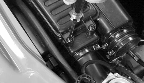
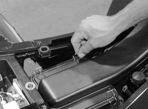
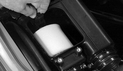
2.Remove the two machine screws securing the air cleaner housing cover, (Fig.7).
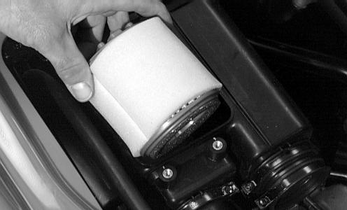
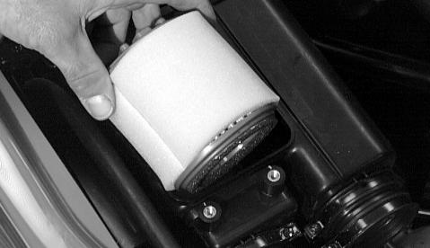
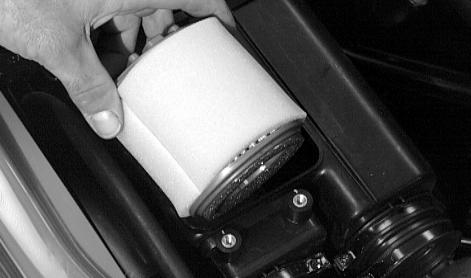
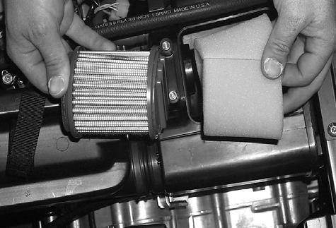
3.Pull the retainer out and remove the filter with foam wrap, (Fig.8).
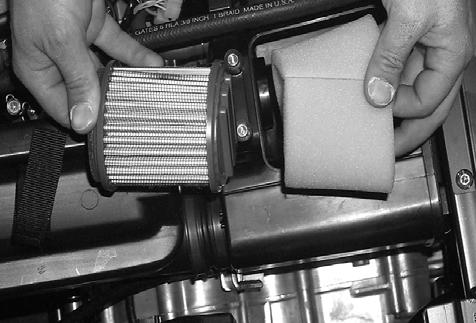
4.Remove the foam wrap from the filter, (Fig.10).
5.Wash the polyester filter and the foam wrap with warm soapy water and rinse.
6.Allow the foam wrap to air dry thoroughly.
NOTE: Either allow the polyester filter to air dry or blow dry using low-pressure compressed air. Direct the compressed air through the filter from the opposite direction as normal operation air flow.
CAUTION: Do not put oil on either the filter or the foam wrap.
7.Place the foam wrap around the air filter; then install the filter with wrap into the air cleaner making sure it is properly in position and properly seated and secure with the retainer.
Fig.7
Fig.8
Fig.9
Fig.10
8.Install the air cleaner housing cover and secure with the machine screws; then install the seat making sure the seat is properly secured.
9.Check the drain tube for petrol or oil accumulation. If noticed, remove the drain tube cap from beneath the cleaner, drain the petrol or oil into a suitable container, and install and secure the tube cap.
10.Inspect “duck bill” drain beneath the air cleaner for debris and sealing, (Fig.11).
Fig.11
Maintenance
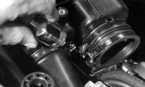
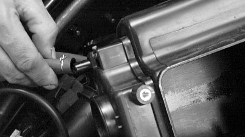
REMOVING AIR CLEANER
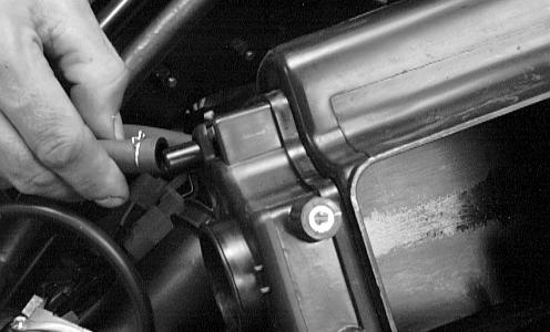
Fig.12 - Remove the seat; then remove the air-intake snorkel.
Fig.13
Fig.14 - Remove the two machine screws securing the air cleaner housing cover.
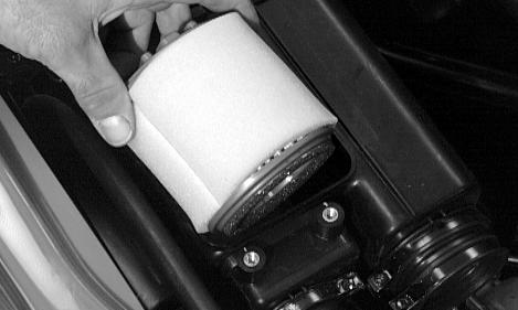
Fig.15 - Pull the retainer out and remove the filter with foam wrap.
Fig.16
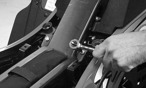
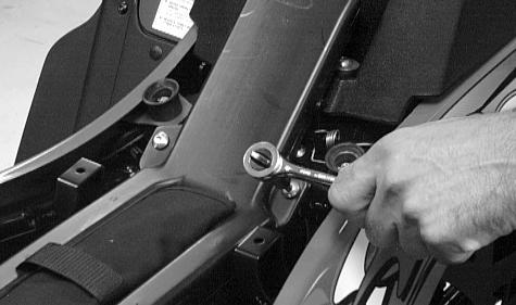
Fig.17 - Remove the machine screws securing the air cleaner to the frame.
Fig.18 - Remove the air cleaner from the frame (not shown).
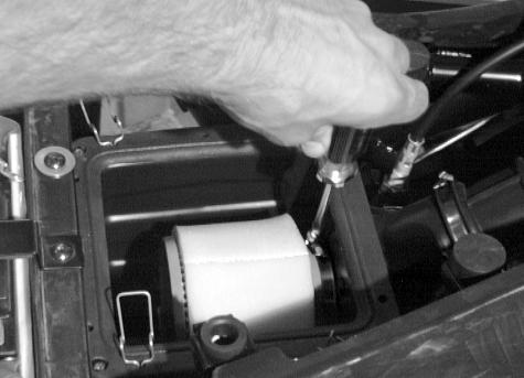
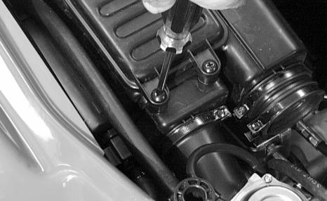
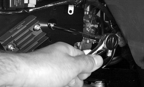
Fig.20 - Loosen the clamp securing the air cleaner to the carburettor boot.
Fig.21 - Remove the crankcase breather hose from the air cleaner.
Fig.19
Fig.20
Fig.21
Maintenance
Fig.22 - 250/300 cc
1. Air cleaner assy8. Clamp15. Clamp
2. Retainer9. Drain plug16. Snorkel
3. Filter w/sleeve10. Valve17. Lock washer
4. Cap11. Clamp18. Strap
5. Cap screw12. Hose assy19. Plastic rivet
6. Joint13. Clamp20. Tool kit
7. Clamp14. Boot21. Cap screw
INSTALLING AIR CLEANER
1.Place the air cleaner into the frame; then connect the crankcase breather hose.
2.Secure the carburettor boot to the air cleaner.
3.Install the machine screws securing the air cleaner to the frame.
4.Install the filter with foam wrap into the air cleaner; then secure with the retainer.
5.Install the air cleaner housing cover and secure with the machine screws.
6.Install the air-intake snorkel.
7.Install the seat making sure it is properly secured.
AIR CLEANER/FILTER
The air filter inside the air filter housing must be kept clean to provide good engine power and petrol mileage. If the AgTV is used under normal conditions, service the filter at the intervals specified. If operated in dusty, wet, or muddy conditions, inspect and service the filter more frequently. Use the following procedure to remove the filter and inspect and/or clean it.
Cleaning and inspecting filter
CAUTION: Failure to inspect the air filter frequently if the vehicle is used in dusty, wet, or muddy conditions can damage the engine.
1.Remove the seat.
2.Remove the air filter housing cover from the retaining clips.
3.Loosen the clamp; then remove the filter.
4.Fill a wash pan larger than the filter with a nonflammable cleaning solvent; then dip the filter in the solvent and wash it.
NOTE: Foam Filter Cleaner (ATV0436-194) and Foam Filter Oil (ATV0436-195) are available from MASSEY FERGUSON.
5.Dry the filter.
6.Put the filter in a plastic bag; then pour in air filter oil and work the filter.
CAUTION: A torn air filter can cause damage to the AgTV engine. Dirt and dust may get inside the engine if the element is torn. Carefully examine the element for tears before and after cleaning it. Replace the element with a new one if it is torn.
7.Clean any dirt or debris from inside the air cleaner. Be sure no dirt enters the carburettor.
8.Place the filter in the air filter housing making sure it is properly in position and properly seated and secure with the clamp.
9.Install the air filter housing cover and secure with the retaining clips; then install the seat making sure the seat is properly secured.
Fig.23
Fig.24
Fig.25
Maintenance
Checking/draining drain tube
1.Periodically check the drain tube for petrol or oil accumulation. If noticed, remove the drain tube cap from beneath the front housing, drain the petrol or oil into a suitable container, and install and secure the tube cap.
2.Inspect “duck bill” drain beneath the main housing for debris and for proper sealing, (Fig.27).
Fig.26
Fig.27
Removing air cleaner
1.Remove the seat.
2.Remove the air cleaner cover from the retaining clips.
3.Loosen the clamp and remove the filter, (Fig.29).
4.Loosen the clamp securing the air cleaner to the front boot; then loosen the clamp securing the air cleaner to the rear filter sleeve.
5.Remove the machine screws securing the air cleaner to the flange support and frame.
6.Remove the air cleaner from the frame.
Fig.28
Fig.29
Maintenance
1. Clamp8. Clamp15. Valve
2. Boot9. Spring16. Drain cap
3. Clamp10. Machine screw17. Clamp
4. Housing11. Expansion nut18. Clamp
5. Self-tapping screw12. Vent hose19. Support
6. Gasket13. Filter20. Heat plate
7. Snorkel14. Sleeve21. Clamp
Fig.30
Installing
1.Place the air cleaner into the frame.
2.Install the machine screws securing the air cleaner to the flange support and frame.
3.Install the rear filter sleeve onto the air cleaner; then tighten the clamp securely.
4.Install the front boot onto the air cleaner; then tighten the clamp securely.
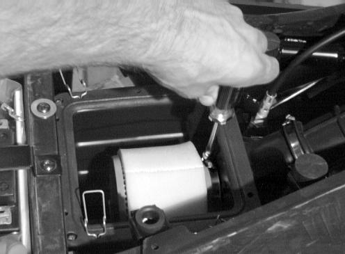
5.Install the filter with foam wrap into the air cleaner; then tighten the clamp securely, (Fig.31).
6.Place the air cleaner cover into position and secure with the retaining clips, (Fig.32).
7.Install the seat making sure the seat is properly secured.
Fig.31
Fig.32
Maintenance
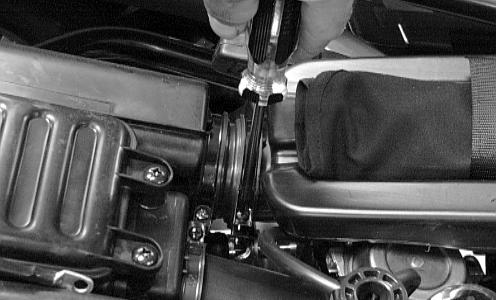
VALVE/TAPPET CLEARANCE
Feeler Gauge Procedure
To check and adjust valve/tappet clearance, use the following procedure.
NOTE: On the 250/300 cc, the seat and air-intake snorkel must be removed for this procedure.
1.Remove the timing inspection plug; then remove the tappet covers (for more detailed information, see Section 3A - Servicing Top-Side Components).
2.Rotate the crankshaft to the TDC position on the compression stroke.
NOTE: At this point, the rocker arms and adjuster screws must not have pressure on them.
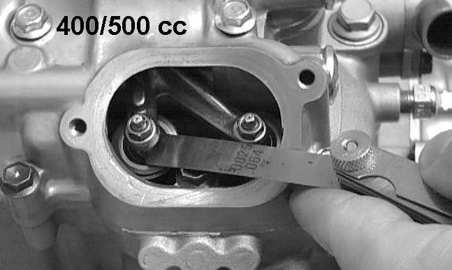
3.Using a feeler gauge, check each valve/tappet clearance. If clearance is not within specifications, loosen the jam nut and rotate the tappet adjuster screw until the clearance is within specifications. Tighten each jam nut securely after completing the adjustment.
CAUTION: The feeler gauge must be positioned at the same angle as the valve and valve adjuster for an accurate measurement of clearance. Failure to measure the valve clearance accurately could cause valve component damage.
4.Install the timing inspection plug.
5.Place the two tappet covers into position making sure the proper cap screws are with the proper cover. Tighten the cap screws securely.
Valve/Tappet Clearance (250/300) cc (Fig.33)
Intake0.13 mm (0.005 in)
Exhaust0.25 mm (0.010 in)
Fig.33
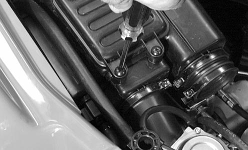
VALVE/TAPPET CLEARANCE
Valve Adjuster Procedure
To check and adjust valve/tappet clearance, use the following procedure.
NOTE: On the 250/300 cc, the seat and air-intake snorkel must be removed for this procedure.
1.Remove the timing inspection plug; then remove the tappet covers (for more detailed information, see Section 3A - Servicing Top-Side Components).
2.Rotate the crankshaft to the TDC position on the compression stroke.
NOTE: At this point, the rocker arms and adjuster screws must not have pressure on them.
NOTE: Use Valve Gap Adjuster (ATV0444-092) for the 250/300 cc.
3.Place the valve adjuster onto the jam nut securing the tappet adjuster screw; then rotate the valve adjuster dial clockwise until the end is seated in the tappet adjuster screw.
4.While holding the valve adjuster dial in place, use the valve adjuster handle and loosen the jam nut; then rotate the tappet adjuster screw clockwise until friction is felt.
5.Align the valve adjuster handle with one of the marks on the valve adjuster dial.
6.While holding the valve adjuster handle in place, rotate the valve adjuster dial counter clockwise until proper valve/tappet clearance is attained.
NOTE: Refer to the appropriate Specifications for the proper valve/tappet clearance.
NOTE: Rotating the valve adjuster dial counter clockwise will open the valve/tappet clearance by 0.05 mm (0.002 in.) per mark.
7.While holding the adjuster dial at the proper clearance setting, tighten the jam nut securely with the valve adjuster handle.
8.Place the two tappet covers with O-rings into position; then tighten the covers securely (Fig.34).
9.Install the spark plug; then install the timing inspection plug (Fig.35).
Fig.34
Fig.35
CLICK HERE TO DOWNLOAD THE COMPLETE MANUAL
• Thank you very much for reading the preview of the manual.
• You can download the complete manual from: www.heydownloads.com by clicking the link below
• Please note: If there is no response to CLICKING the link, please download this PDF first and then click on it.
CLICK HERE TO DOWNLOAD THE
Maintenance
TESTING ENGINE COMPRESSION
To test engine compression, use the following procedure.
1.Remove the high tension lead from the spark plug.
2.Using compressed air, blow any debris from around the spark plug.
WARNING: Always wear safety glasses when using compressed air.
3.Remove the spark plug; then attach the high tension lead to the plug and ground the plug on the cylinder head well away from the spark plug hole.
4.Attach the Compression Gauge (ATV0444-096).
NOTE: The engine must be warm and the battery must be fully charged for this test.
5.While holding the throttle lever in the full-open position, crank the engine over with the electric starter until the gauge shows a peak reading (five to 10 compression strokes).
NOTE: For the 250/300 cc, the compression should be within a range of 157.5-192.5 Ibf/in2 in the full-open throttle position.
6.If compression is abnormally low, inspect the following items.
A - Verify starter cranks engine over.
B - Gauge is functioning properly.
C - Throttle lever in the full-open position.
D - Valve/tappet clearance correct.
E - Valve bent or burned.
F - Valve seat burned.
NOTE: To service valves, see Section 3A.
7.Pour 29.5 ml (1 fl oz) of oil into the spark plug hole, reattach the gauge, and retest compression.
8.If compression is now evident, service the piston rings, (see Section 3A).
SPARK PLUG
A light brown insulator indicates that the plug is correct. A white or dark insulator indicates that the engine may need to be serviced or the carburettor may need to be adjusted. To maintain a hot, strong spark, keep the plug free of carbon, (Fig.36).
CAUTION: Before removing the spark plug, be sure to clean the area around the spark plug. Dirt could enter engine when removing or installing the spark plug. Adjust the gap to 0.6 - 0.7 mm (0.024 - 0.028 in.) on the 250/300 cc, (Fig.37).
When installing the spark plug, be sure to tighten it securely. A new spark plug should be tightened 1/2 turn once the washer contacts the cylinder head. A used spark plug should be tightened 1/8 - 1/4 turn once the washer contacts the cylinder head.
Fig.36
Fig.37
Maintenance
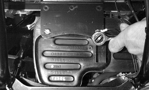
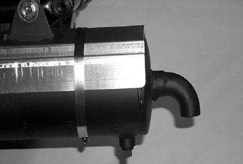
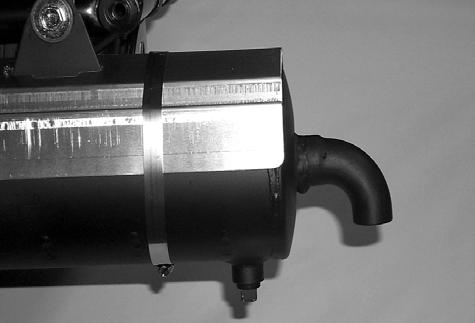
MUFFLER/SPARK ARRESTER
The muffler has a spark arrester which must be periodically cleaned. At the intervals shown in the Periodic Maintenance Chart, clean the spark arrester using the following procedure.
WARNING: Wait until the muffler cools to avoid burns.
1.Elevate the front of the AgTV on a safety stand until the muffler is horizontal.
2.Shift the transmission into neutral and set the parking brake.
3.Remove the plug from the bottom of the muffler, Fig.38.
4.Start the engine and increase RPM to blow out the accumulated carbon particles.
5.Stop the engine. Wait until the muffler cools; then install the plug and tighten securely.
FUEL/VENT HOSES
Replace the fuel hose every two years. Damage from aging may not always be visible. Do not bend or obstruct the routing of the carburettor vent hose. Make certain that the vent hose is securely connected to the carburettor and the opposite end is always open.
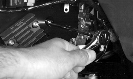
ADJUSTING THROTTLE CABLE
To adjust the throttle cable free-play, follow this procedure.
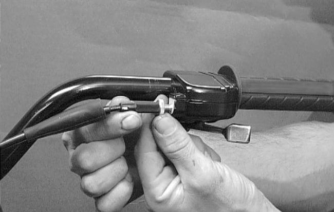
1.Slide the rubber boot away; then loosen the jam nut from the throttle cable adjuster, (Fig.39).
2.Slide the rubber boot away and turn the adjuster until the throttle cable has proper free-play of 3-6 mm (1/8 - 1/4 in.) at the lever, (Fig.40).
3.Tighten the jam nut against the throttle cable adjuster securely; then slide the rubber boot over the adjuster.
Fig.38
Fig.39
Fig.40
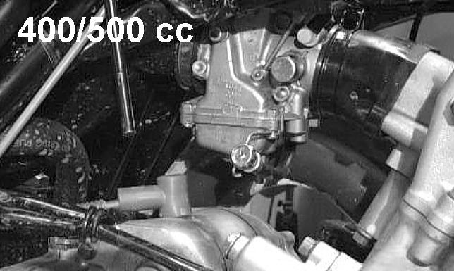
ADJUSTING ENGINE RPM (IDLE)
To properly adjust the idle RPM, a tachometer is necessary. To adjust idle RPM, use the following procedure.
1.With the transmission in neutral, start the engine and warm it up to normal operating temperature.
2.Turn the idle adjustment screw clockwise one turn past the recommended RPM setting; then turn it counter clockwise to the correct RPM setting, (Fig.41).
WARNING: Adjust the idle to the correct RPM. Make sure the engine is at normal operating temperature before adjusting the idle RPM.
Fig.41
Maintenance
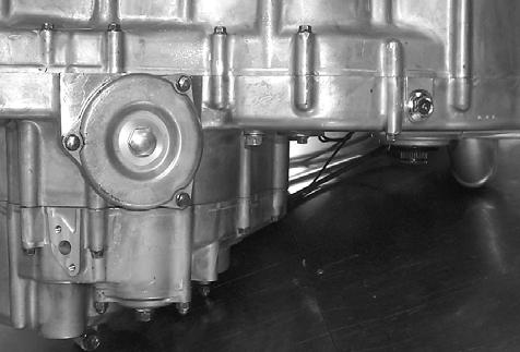
ENGINE/TRANSMISSION
Oil - Filter - Strainer(250/300 cc)
Oil - filter
Change the engine oil and oil filter at the scheduled intervals. The engine should always be warm when the oil is changed so the oil will drain easily and completely.
1.Park the AgTV on level ground.
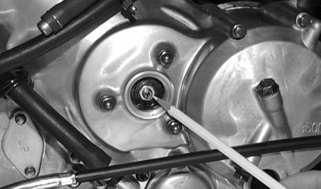
2.Remove the oil filler plug, (Fig.42).
3.Remove both drain plugs from the bottom of the engine and drain the oil into a drain pan, (Fig.43).
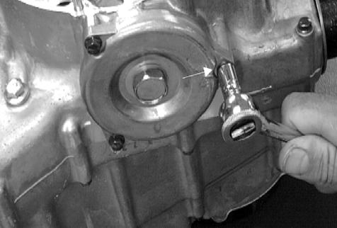
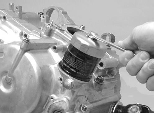
4.Remove the nuts securing the filter cover.
5.Noting the position of the arrow on the oil filter cover, remove the oil filter cover; then pull out the oil filter element (Fig.44).
6.Apply oil to the O-rings and check to make sure they are positioned correctly in the cover and crankcase; then with the open end of the filter element directed toward the centre of the engine, install the element making sure the spring is between the cover and the element, (Fig.45).
NOTE: Clean up any excess oil after removing the filter.
CAUTION: If the oil filter element is installed backwards, engine damage will occur due to lack of oil flow.
7.Place the filter cover in position and secure with the nut. Tighten securely.
8.Install the engine drain plug and tighten to 2.2 kg-m (16 Ibf/ft.). Pour 3.9 L of the recommended oil in the filler hole; then install the filler plug.
CAUTION: Any oil used in place of the recommended oil could cause serious engine damage. Do not use oils which contain graphite or molybdenum additives. These oils can adversely affect clutch operation. Also, not recommended are racing, vegetable, non-detergent, and castor-based oils.
9.Start the engine (while the AgTV is outside on level ground) and allow it to idle for a few minutes.
10.Turn the engine off and wait approximately one minute. Recheck the oil level in the engine oil inspection window. The oil level should be visible through the window. If oil is not visible, add recommended oil until the oil level is visible between the lines of the window, (Fig.46).
Fig.42
Fig.43
Fig.44
1. Engine oil pump9. O - ring16. Check plug
2. Driven gear10. Cap screw17. Gasket
3. Pin11. Drain plug18. Cap O - ring
4. Circlip12. Gasket19. Spring
5. Cap screw13. Filter20. Stud bolt
6. Strainer14. Filter O - ring21. Stud bolt
7. Cap screw15. Cap22. Nut
8. Cap
- Inspect the area around the drain plug and oil filter for leaks
Fig.45
Fig.46
Maintenance
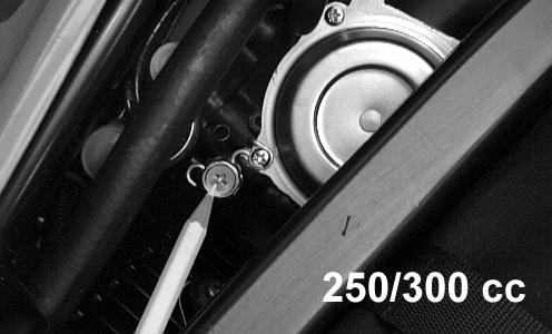
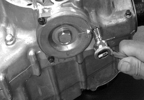
STRAINER
To check the oil strainer, use the following procedure.
1.Remove the skid plate.
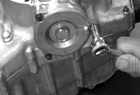
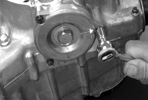
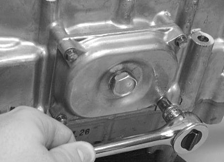
2.Remove the Phillips-head cap screws securing the oil strainer cap; then remove the cap. Note the directional arrow on the cap for assembly purposes, (Fig.47).
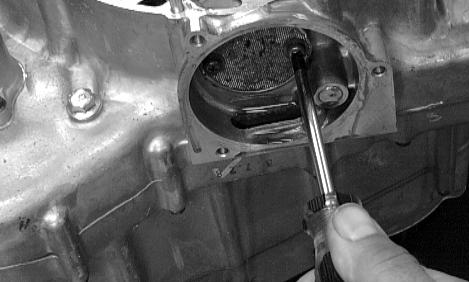
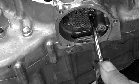
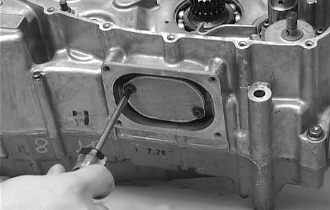
3.Remove the Phillips-head screws securing the strainer; then remove the strainer, (Fig.48).
NOTE: To service the oil strainer, see Section 3A.
4.Place the oil strainer into position and secure with the Phillips-head screws.
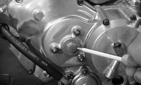
5.Place the strainer cap into position on the crankcase; then secure with the Phillips-head cap screws (coated with red Loctite 271).Tighten securely, (Fig.49).
6.Install the skid plate.
Fig.47
Fig.48
Fig.49
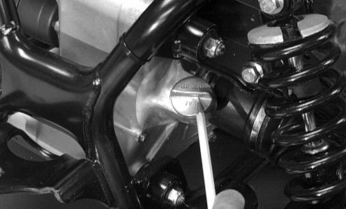
FRONT DIFFERENTIAL/REAR DRIVE LUBRICANT
Inspect and change the lubricant according to the Periodic Maintenance Chart. When changing the lubricant, use approved SAE 80W-90 hypoid gear lube. To change lubricant, use the following procedure.
1.Place the AgTV on level ground.
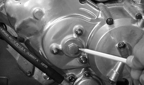
2.Remove the filler plug, (Fig.50).
3.Drain the lubricant into a drain pan by removing the drain plug from the bottom of the case, (Fig.52).
4.After all the lubricant has been drained, install the drain plug and tighten to 2.2 kg-m (16 Ibf/ft).
5.Pour the correct amount of recommended lubricant into the filler hole.
6.Install the filler plug.
NOTE: If the differential lubricant is contaminated with water, inspect the drain plug, filler plug, and/or bladder.
CAUTION: Water entering the outer end of the axle will not be able to enter the rear drive unless the seals are damaged.
Fig.50
Fig.51
Fig.52
Maintenance
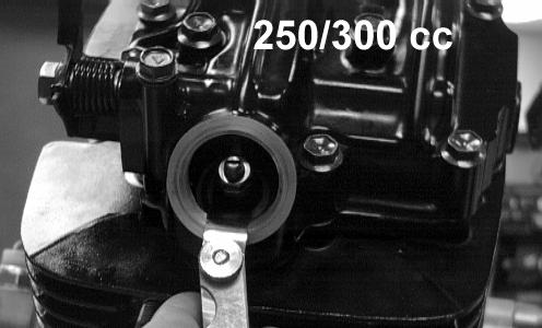
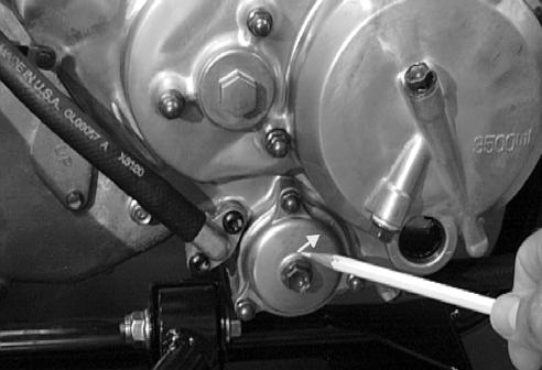
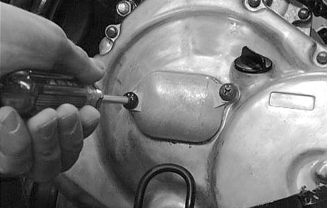
ADJUSTING CLUTCH (250/300 CC)
To adjust the clutch, use the following procedure.
1.Using an impact driver, remove the cover. Account for the O-ring, (Fig.53).
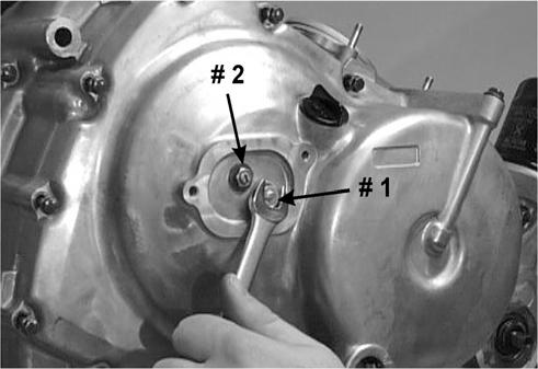
2.Loosen the jam nut securing the adjustment screw ().
3.Rotate the adjustment screw clockwise until it stops.
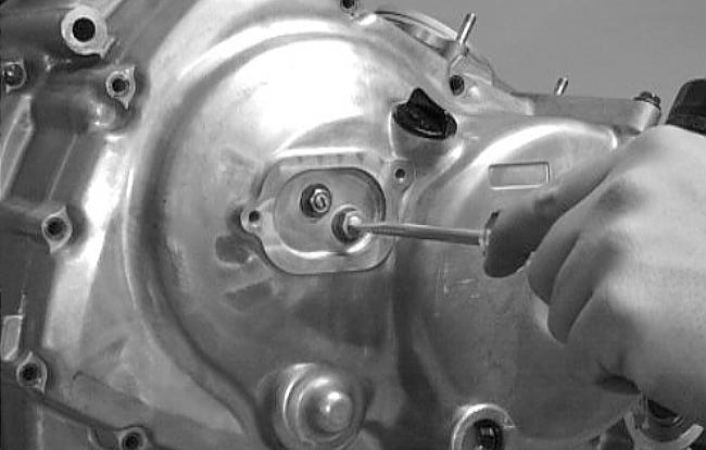
4.Rotate the adjustment screw counterclockwise 1/8 turn; then lock the jam nut securing the adjustment screw, (Fig.54).
NOTE: At this point the clutch should be adjusted correctly. Test ride the AgTV to ensure accurate adjustment.
5.Secure the cover making sure the O-ring is properly positioned, (Fig.55).
Fig.53
Fig.54
Fig.55
TYRES
Tyre sizes
The AgTV is equipped with low-pressure tubeless tyres of the size and type listed. Do not under any circumstances substitute tyres of a different type or size.
250 ccFront Rear
SizeAT23 x 8-12AT24 x 9-12
300 ccFrontRear
Size (4x4)AT24 x 9-12AT25 x 10-12
Size (2x4)AT23 x 8-12AT25 x 10-12
WARNING: Always use the size and type of tyres specified. Always maintain proper tyre inflation pressure.
Tyre inflation pressure
On all models, front and rear tyre inflation pressure should be 0.35 kg-cm2 (5.0 Ibf/in2 ).
A low-pressure gauge is provided in the tool kit to measure the air pressure in the tyres. Check the air pressure in all tyres before each use of the AgTV.
STEERING COMPONENTS
The following steering components should be inspected periodically to ensure safe and proper operation.
A - Handlebar grips worn, broken, or loose.
B - Handlebar bent, cracked, and equal and complete fullleft and full-right capability.
C - Steering post bearing assembly/bearing housing broken, worn, or binding.
D - Ball joints worn, cracked, or damaged.
E - Tie rods bent or cracked.
F - Knuckles worn, cracked, or damaged.
G - Cotter pins damaged or missing.
DRIVESHAFT/COUPLING
The following drive system components should be inspected periodically to ensure proper operation.
A - Spline lateral movement (slop).
B - Rubber coupling cracked, damaged, or worn.
SUSPENSION/SHOCK ABSORBERS/ BUSHINGS
The following suspension system components should be inspected periodically to ensure proper operation.
A - Shock absorber rods bent, pitted, or damaged.
B - Rubber damper cracked, broken, or missing.
C - Shock absorber body damaged, punctured, or leaking.
D - Shock absorber eyelets broken, bent, or cracked.
E - Shock absorber eyelet bushings worn, deteriorated, cracked, or missing.
F - Shock absorber spring broken or sagging.
NUTS/CAP SCREWS
Tighten all nuts and cap screws. Make sure rivets holding components together are tight. Replace all loose rivets. Care must be taken that all calibrated nuts and cap screws are tightened to specifications.
IGNITION TIMING
The ignition timing cannot be adjusted; however, verifying ignition timing can aid in troubleshooting other components. To verify engine timing, use the following procedure.
1.Attach the engine Timing Light (ATV0644-197) to the spark plug high tension lead; then remove the timing inspection plug from the left-side crankcase cover.
2.Using the AgTV Tachometer (ATV0644-275), start the engine and run at the recommended RPM; ignition timing should be the recommended degrees BTDC.
Ignition Timing
ModelTiming/RPM
250 cc5° below 1800 35° above 3800
3.Install the timing inspection plug.
If ignition timing cannot be verified, the rotor may be damaged, the key may be sheared, the trigger coil bracket may be bent or damaged, or the CDI unit may be faulty.
CLICK HERE TO DOWNLOAD THE COMPLETE MANUAL
• Thank you very much for reading the preview of the manual.
• You can download the complete manual from: www.heydownloads.com by clicking the link below
• Please note: If there is no response to CLICKING the link, please download this PDF first and then click on it.
CLICK HERE TO DOWNLOAD THE
Maintenance
HEADLIGHT/TAILLIGHT/BRAKELIGHT
Each time the AgTV is used, lights should be checked for proper function. Rotate the ignition switch to the lights position; the headlights and taillight should illuminate. Test the brakelight by compressing the brake lever. The brakelight should illuminate.
Headlight
To replace the headlight bulb, use the following procedure.
CAUTION: The bulb portion of the headlight is fragile. HANDLE WITH CARE. When replacing the headlight bulb, do not touch the glass portion of the bulb. If the glass is touched, it must be cleaned with a dry cloth before installing.
1.Remove the machine screw from beneath the headlight housing; then remove the lens cover.
NOTE: It may be necessary to carefully pull a certain amount of wiring harness slack through the housing for socket removal.
2.Push in on the wiring harness socket and turn it counterclockwise to free the bulb; then remove the bulb.
3.Place the new bulb into position making sure the tab on the bulb base aligns with the recess in the housing.
4.Install the wiring harness socket making sure the tab in the socket aligns with its recess. Turn clockwise to lock socket in place.
NOTE: If wiring harness slack was established for removing the socket, carefully pull the wiring harness back through the housing.
5.Place the headlight into the housing and install the lens cover.
6.Install the machine screw and tighten until snug.
Taillight - brakelight
To replace the taillight-brakelight bulb, use the following procedure.
1.Remove the two screws and remove the lens cover.
2.Push the bulb in and turn it counter clockwise.
3.Install the new bulb by turning it clockwise while pushing in.
4.Install the lens cover.
CAUTION: Tighten the lens cover screws only until they are snug.
Checking/adjusting headlight aim
The headlights can be adjusted vertically and horizontally. The geometric centre of the MAIN beam light zone is to be used for vertical and horizontal aiming.
Fig.56
1.Position the AgTV on a level floor so the headlights are approximately 6.1 m (20 ft) from an aiming surface (wall or similar aiming surface).
NOTE: There should be an average operating load on the MF AgTV when adjusting the headlight aim.
2.Measure the distance from the floor to the mid-point of each headlight.
3.Using the measurements obtained in step 2, make horizontal marks on the aiming surface.
4.Make vertical marks which intersect the horizontal marks on the aiming surface directly in front of the headlights.
5.Switch on the lights. Make sure the MAIN BEAM is on. DO NOT USE DIPPED BEAM.
6.Observe each headlight beam aim. Proper aim is when the most intense beam is centered on the vertical mark 5 cm (2 in.) below the horizontal mark on the aiming surface, (Fig.56).
7.Adjust each headlight until correct aim is obtained.
A - Horizontal: Loosen the nut beneath the headlight mounting grommet; then adjust for proper aiming. Tighten the nut securely.
B - Vertical: Loosen the nut on the side of the headlight housing; then adjust for proper aiming. Tighten the nut securely.
SWITCHES
Each time the AgTV is used, switches should be checked for proper operation. Use the following list for reference.
Ignition switch — engine will start.
A - Emergency stop switch - engine will stop.
B - Reverse switch - reverse indicator light illuminates.
C - Hi/Lo switch - headlight beam bright and dim.
D - Brake switches - rear brakelight illuminates.
ADJUSTING REVERSE SHIFT LEVER (MANUAL TRANSMISSION)
To shift into reverse gear, stop the AgTV completely and shift the transmission into neutral. Pull the reverse shift lever fully rearward. When the AgTV is in reverse gear, the gearshift pedal will not function and the reverse gear indicator light should be illuminated.
WARNING: Never shift the AgTV into reverse gear when it is moving as it could cause it to stop suddenly throwing the operator from the vehicle.
If the reverse lever light does not illuminate when shifted to the reverse position, the switch may be faulty, the fuse may be blown, the bulb may be faulty, a connection may be loose or corroded, or the lever may need adjusting. To adjust, use the following procedure.
1.Shift the lever to the forward position.
2.Disconnect the cable from the reverse shift arm by removing the clevis pin/clip.
3.At the adjuster, loosen the upper jam nut and thread it to the middle of the adjuster.
4.Shift the lever to the reverse position.
5.At the reverse shift arm, attempt to line the cable connector with the engine arm and install the clevis pin/clip.
6.If the clevis pin/clip cannot be installed, adjust the “lower” jam nut until it can be installed.
7.Tighten the lower jam nut and the upper jam nut to secure the adjustment.
NOTE: At this point the reverse lever should be adjusted correctly. If the indicator light does not illuminate, troubleshoot the other possible reasons.
Place the shift lever in the Reverse position. The reverse gear indicator light should illuminate.
WARNING: Never shift the AgTV into reverse gear when it is moving as it could cause it to stop suddenly throwing the operator from the vehicle.
If the reverse gear indicator light does not illuminate when shifted to the reverse position, the switch may be faulty, the fuse may be blown, the bulb may be faulty, a connection may be loose or corroded, or the lever may need adjusting. To adjust, use the following procedure.
1.Shift the lever to the Neutral position.
2.Disconnect the cable from the shift select arm (located on the left side of the engine) by removing the E-ring.
3.At the adjuster (located under the right-front fender), loosen the front jam nut and thread it to the middle of the adjuster.
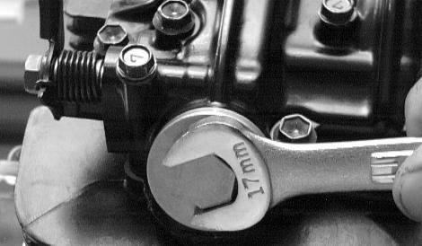
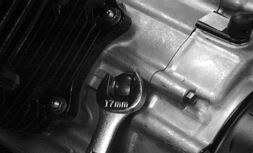
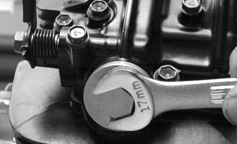
4.With both the shift select arm and shift lever in the neutral position, adjust the front and rear jam nuts using two 3/4 in. open-end wrenches.
NOTE: Adjust the jam nuts until the cable eye can be installed on the shift select arm without moving the shift lever or the shift select arm out of the neutral position.
5.Secure the cable to the shift select arm with the existing E-ring.
6.Tighten the front and rear jam nuts to secure the adjustment.
NOTE: At this point the lever should be adjusted correctly. If the indicator light does not illuminate, troubleshoot the other possible reasons.
Fig.57
Fig.58
Maintenance
INDICATOR/GEAR POSITION LIGHTS
Each time the AgTV is used, the lights should be checked for proper function. Use the following for reference.
Indicator lights (250 cc/300 cc) (Fig.59)
1.High Beam Indicator - A blue light will illuminate when the lights are on high beam. The light will not be illuminated when the lights are switched to low beam.
2.Temperature Indicator - A red light will illuminate if the engine overheats. The light should be off during normal operation.
CAUTION: Continued operation of the AgTV with high engine temperature may result in engine damage or premature wear.
3.Neutral Indicator - A green light will illuminate when the transmission is in neutral and the ignition switch is on. The light will go out when shifted into any gear other than neutral.
4.Reverse Indicator - An orange light will illuminate when the transmission is shifted into reverse gear. The light will go off when shifted out of reverse.
CAUTION: Continued operation of the AgTV with high engine temperature may result in engine damage or premature wear.
NOTE: High engine RPM, low vehicle speed, or heavy load can raise engine temperature. Decreasing engine RPM, reducing load, and selecting an appropriate transmission gear can lower the temperature.
NOTE: Debris in front of the engine packed between the oil cooler cooling fins on the 300 cc can reduce cooling capability. Using a hose, pressure-wash the radiator (engine and oil cooler on the 300 cc) to remove any debris preventing air flow to the radiator.
Fig.60 - 300 cc 4x4
Gear position lights (300 cc 4x4 - Manual Transmission) Fig.60
1.High Beam Indicator - A blue light will illuminate when the lights are on high beam. The light will not be illuminated when the lights are switched to low beam.
2.Temperature Indicator - A red light will illuminate if the engine overheats. The light should be off during normal operation.
3.Neutral Indicator - A green light will illuminate when the transmission is in neutral and the ignition switch is on. The light will go out when shifted into any gear other than neutral.
4.Reverse Indicator - An orange light will illuminate when the transmission is shifted into reverse gear. The light will go off when shifted out of reverse.
5.Gear Position Indicator - A yellow light will illuminate to indicate which gear (1-5) the transmission is shifted into.
Fig.59 - 250 cc
FRAME/WELDS/RACKS
The frame, welds, and racks should be checked periodically for damage, bends, cracks, deterioration, broken components, and missing components. If replacement or repair constitutes removal, see Section 8.
ELECTRICAL CONNECTIONS
The electrical connections should be checked periodically for proper function. In case of an electrical failure, check fuses, connections (for tightness, corrosion, damage), and/or bulbs. If an electrical component needs to be tested for proper function, see Section 5.
HYDRAULIC HANDBRAKE SYSTEM
Checking/bleeding
The hydraulic brake system has been filled and bled at the factory. To check and/or bleed the hydraulic brake system, use the following procedure.
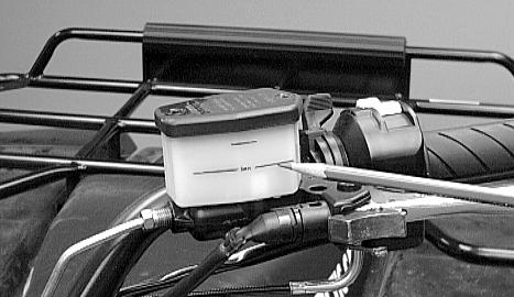
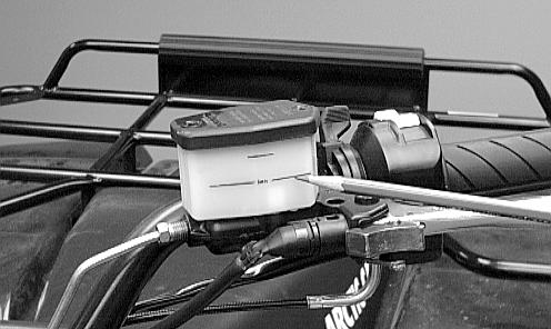
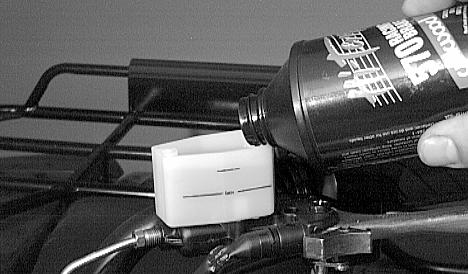
1.With the master cylinder in a level position, check the fluid level. It must be above the minimum line and below the maximum line, (Fig.61).
2.Compress the brake lever several times to check for a firm lever. If the lever is not firm, the brake system must be bled.
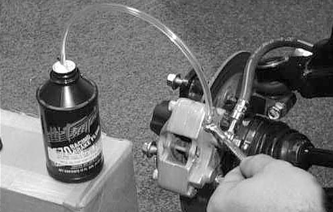
3.To bleed the brake system, use the following procedure, (Fig.62).
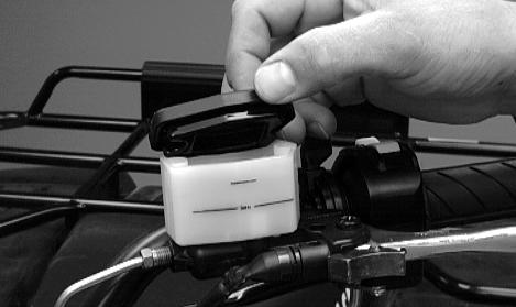
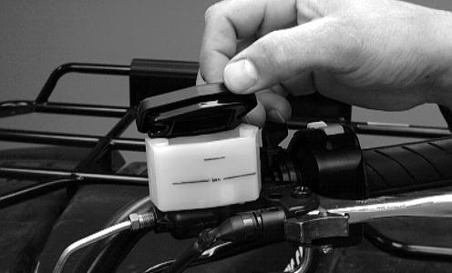
A - Remove the cover and fill the master cylinder to the maximum line of the reservoir with DOT 4 Hi-Temp Brake Fluid (ATV1639-799).
B - Install and secure the cover; then slowly compress the brake lever several times, (Fig.63).
C - Remove the protective cap, install one end of a clear hose onto one FRONT bleeder screw, and direct the other end into a container; then while holding slight pressure on the brake lever, open the bleeder screw and watch for air bubbles. Close the bleeder screw before releasing the brake lever. Repeat this procedure until no air bubbles are present.
NOTE: During the bleeding procedure, watch the master cylinder reservoir very closely to make sure there is always a sufficient amount of brake fluid. If the fluid level gets below the bottom line on the reservoir, refill the reservoir before the bleeding procedure is continued.
D - Repeat step C until the brake lever is firm.
E - At this point, perform step B, C, and D on the other FRONT bleeder screw; then move to the REAR bleeder screw and follow the same procedure.
Carefully check the entire hydraulic brake system that all hose connections are tight, the bleed screws are tight, the protective caps are installed, and no leakage is present.
Fig.61
Fig.62
Fig.63
Fig.64
Maintenance
CAUTION: This hydraulic brake system is designed to use high-temperature DOT 4 brake fluid only. If brake fluid must be added, care must be taken as brake fluid is very corrosive to painted surfaces.
WARNING: Using the Operator’s Manual as a guide, instruct the customer on the proper use, care, burnishing procedure, and maintenance of the hydraulic brake system.
Inspecting Hoses
Carefully inspect the hydraulic brake hoses for cracks or other damage. If found, the brake hoses must be replaced.
Checking/Replacing pads
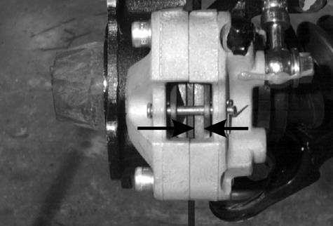
The clearance between the brake pads and brake discs is adjusted automatically as the brake pads wear. The only maintenance that is required is replacement of the brake pads when they show excessive wear. Check the thickness of each of the brake pads as follows.
1.Remove a front wheel.
2.Measure the thickness of each brake pad, (Fig.65).
3.If thickness of either brake pad is less than 3.2 mm (0.125 in.), the brake pads must be replaced.
NOTE: The brake pads should be replaced as a set.
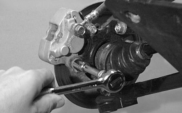
4.To replace the brake pads, use the following procedure.
A - Remove the wheel.
B - Remove the cap screws securing the calliper to the bracket; then remove the cotter pin securing the pads and remove the pads, (Fig.66).
C - Install the new brake pads; then secure with the pin and cotter pin. Spread the cotter pin.
D - Secure the calliper to the knuckle and/or axle housing with the cap screws. Tighten to 2.8 kg-m (20 Ibf/ft) (Fig.66).
E - Install the wheel. Tighten to 6.9 kg-m (50 lbf/ft).
5.Burnish the brake pads (see Burnishing Brake Pads in this section).
Fig.65
Fig.66
MECHANICAL FOOT BRAKE (MANUAL TRANSMISSION)
Checking
Although the rear brake has been adjusted at the factory, the brake should be checked for proper operation. The mechanical brake must be maintained to be fully functional.
1.With the engine off, transmission in neutral,and the reverse lever in the forward position, press the foot brake pedal and attempt to move the AgTV.
2.If the rear wheels are locked, it is adjusted properly.
3.If the rear wheels are not locked, it must be adjusted, (set up).
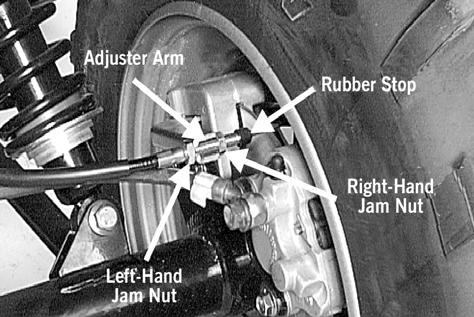
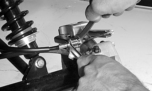
Adjusting
To adjust (set up) the mechanical brake, use the following procedure.
1.Loosen the right-hand jam nut (wheel-side when viewing from behind) of the adjuster arm.
2.Pull the brake cable to the left and push the adjuster arm to the right.
3.While holding the cable and adjuster arm in this position, finger-tighten the left-hand jam nut until it contacts the adjuster arm; then loosen it 1 1/2 turns.
4.Tighten the right-hand jam nut securely against the adjuster arm.
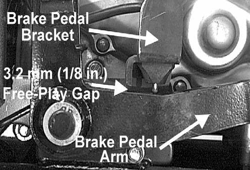
NOTE: At this point, there should be 3.2 mm (1/8in.) free-play gap between the brake pedal arm and the brake pedal bracket.
5.If the free-play gap is not within tolerance, readjust the jam nuts of the adjuster arm in 1/4 turn increments until the correct free-play gap is attained.
NOTE: Apply the foot brake a number of times to ensure the wheels lock and the brakelight illuminates properly.
6.If the rear cable adjustment is inadequate to attain the proper brake pedal arm free-play gap, make adjustment at the front cable adjuster jam nuts.
CAUTION: If adjusting the rear cable at both ends does not attain proper brake pedal arm free-play, the brake pads must be replaced.
Fig.67
Fig.68
Fig.69
Fig.70
Maintenance
MEASURING/REPLACING BRAKE PADS
Removing
1.Support the AgTV on a suitable stand.
2.Remove the right rear wheel and account for the cap screws.
3.Loosen the rear cable adjuster jam nuts; then remove the cap screws securing the mechanical brake to the axle housing.
4.Remove the brake pads from the calliper.
Inspecting and Measuring
1.Inspect the pads for gouges, chips, or wear.
2.Inspect the disc for gouges, grooves, cracks, and warpage.
3.Using a callipers, measure the thickness of each brake pad.
4.If the thickness of either brake pad is less than 3.2 mm (0.125 in.), the brake pads must be replaced.
NOTE: The brake pads should be replaced as a set.
Installing
1.Place the brake pads into the calliper.
NOTE: The metal backing of the pad will be facing the adjuster arms when installed properly.
2.Slide brake calliper assembly over the brake disc and into position; then secure the calliper with the cap screws (coated with blue Loctite 243) tightened to 2.8 kg-m (20 Ibf/ft).
3.Install the wheel and secure. Tighten to 6.9 kg-m (50 lbf/ft).
4.Adjust the brake, (see Adjusting in this chater).
5.Remove the AgTV from the support stand.
NOTE: Whenever installing new pads, the new pads must be burnished (see Burnishing Brake Pads in this section).
HYDRAULIC FOOT BRAKE SYSTEM (AUTOMATIC TRANSMISSION)
The foot brake must be maintained to be fully functional.
WARNING: Be sure to inspect the hydraulic foot brake system before each use. Always maintain brakes according to the Maintenance Schedule.
1.Check the brake fluid level in the reservoir. If the level in the reservoir is low, add DOT 4 brake fluid.
2.Press the foot brake pedal several times to check for firmness.
3.If the pedal is not firm, the system must be held.
NOTE: To bleed the hydraulic foot brake system, use the basic procedure in Hydraulic Hand Brake System in this section.
BURNISHING BRAKE PADS
Brake pads (both hydraulic and mechanical) must be burnished to achieve full braking effectiveness. Braking distance will be extended until brake pads are properly burnished. To properly burnish the brake pads, use the following procedure.
WARNING: Failure to properly burnish the brake pads could lead to premature brake pad wear or brake loss. Brake loss can result in severe injury.
1.Choose an area large enough to safely accelerate the AgTV to 30 m.p.h. and to brake to a stop.
2.Using third gear, accelerate to 30 m.p.h.; then compress brake lever or apply the mechanical foot brake to decelerate to 0-5 m.p.h.
3.Repeat procedure on each brake system 20 times until brake pads are burnished.
4.Adjust the mechanical brake, if necessary.
5.Verify that the brakelight illuminates when the hand lever is compressed or the brake pedal is depressed.
Section 2-B
Table of Contents
PERIODIC
MAINTENANCE CHART
A = Adjust I = Inspect
C = Clean L = Lubricate
D = Drain R = Replace
ItemInitial service after breakin(First monthor 200 miles)
Air filter/Drain tube
Valve/tappet clearance
Muffler/spark arrester
hoses
Carb float chamber (bowl)
(idle)
Front differential/ reardrive lubricant
Steering components
Front axle
Boots/ driveshaft Universal joint
CLICK HERE TO DOWNLOAD THE COMPLETE MANUAL
• Thank you very much for reading the preview of the manual.
• You can download the complete manual from: www.heydownloads.com by clicking the link below
• Please note: If there is no response to CLICKING the link, please download this PDF first and then click on it.
CLICK HERE TO DOWNLOAD THE
Suspension/ shock absorbers/ bushings
Nuts/cap screws/ screws
Ignition timing
Headlight/ taillightbrakelight
Switches
Frame/Welds/ Racks
Electrical connections
Complete brake system (Hydraulic & Mechanical)
Brake padsII*R
Brake fluid IIR (2yrs)
Brake hosesII R (4 yrs.)
Coolant/ Cooling system IIR (2 yrs.)
Upper arm/ knuckle (rear)
* Service/Inspect more frequently when operating in adverse conditions.
** If a rear arm grease fitting does not accept grease, do not force grease into fitting.
LUBRICATION POINTS
It is advisable to lubricate certain components periodically to ensure free movement. Apply light oil to the components using the following list as reference.
A -Throttle Lever Pivot/Cable Ends.
B - Brake Lever Pivot/Cable Ends.
C - Mechanical Brake Cable Ends.
D - Choke Cable Upper End.
E - Reverse Lever Cable End
F - Idle RPM Screw (carburettor)
G - Upper/Lower Rear Arms (6 Locations - 250/300 cc)
NOTE: If a rear arm grease fitting does not accept grease, do not force grease into the fitting.
Maintenance
BATTERY
The battery is located under the right rear fender. The level of the battery fluid must be kept between the upper and lower level lines at all times. If the level drops below the lower level line, add only distilled water until it reaches upper level line.
WARNING: Battery acid is harmful if it contacts eyes, skin, or clothing. Care must be taken whenever handling a battery.
If the battery is discharged, remove the battery from the AgTV and charge the battery at the standard charging rate of 1.4A x 10 hr.
WARNING: Any time service is performed on a battery, the following must be observed: keep sparks, open flame, cigarettes, or any other flame away. Always wear safety glasses. Protect skin and clothing when handling a battery. When servicing battery in enclosed space, keep the area well-ventilated. Make sure battery venting is not obstructed.
To remove and charge the battery, use the following procedure;
1.Remove the battery hold-down bracket.
2.Remove the negative battery cable; then remove the positive cable and the battery vent tube. Remove the battery from the AgTV. Care should be taken not to damage the vent tube.
WARNING: Avoid spillage and contact with skin, eyes, and clothing.
CAUTION: Do not charge the battery while it is in the AgTV with the battery terminals connected.
3.Remove the vent plugs; then (if necessary) fill the battery with distilled water to the upper level indicated on the battery.
4.Trickle charge the battery at 1.4 amps for 10 hours.
CAUTION: Never exceed the standard charging rate.
5.After charging, check fluid level and fill with distilled water as necessary; then install vent plugs.
CAUTION: Before installing the battery, make sure the ignition switch is in the OFF position.
Fig. 1
Fig.2
Fig.3
6. Place the battery into position in the AgTV and secure with the hold-down bracket.
7.Attach the vent tube and check the vent tube to make sure it is not crimped or obstructed in any way and that it is properly routed through and secured to the frame.
8.Connect cables to the proper terminals: positive cable to the positive terminal (+) and negative cable to the negative terminal (-). Connect the negative cable last, (Fig.4).
CAUTION: Connecting cables in reverse (positive to negative and negative to positive) can cause serious damage to the electrical system.
FUSES
On the 250/300 cc, the fuses are located in the centre of the front fender beneath a snap-on cover, (Fig.5).
On the 400/500 cc, the main fuse is located near the right side of the air silencer. A spare main fuse is stored under the starter motor relay.
NOTE: To remove the fuse, compress the locking tabs on either side of the fuse case and lift out.
On the 400/500 cc, the remaining fuses are located in a fuse block next to the battery under the seat. If there is any type of electrical system failure, always check the fuses first.
CAUTION: Always replace a blown fuse with a fuse of the same type and rating.
Fig.4
Fig.5
Fig.6
Maintenance
AIR CLEANER
The two-part air filter inside the air cleaner must be kept clean to provide good engine power and petrol mileage. If the AgTV is used under normal conditions, service the filter at the intervals specified. If operated in dusty, wet, or muddy conditions, inspect and service the filter more frequently.
Cleaning and inspecting filter
CAUTION: Failure to inspect the air filter frequently if the AgTV is used in dusty, wet, or muddy conditions can damage the AgTV engine.
1.Remove the seat.
2.Remove the two machine screws securing the air cleaner housing cover, (Fig.7).
3.Pull the retainer out and remove the filter with foam wrap, (Fig.8).
4.Remove the foam wrap from the filter, (Fig.10).
5.Wash the polyester filter and the foam wrap with warm soapy water and rinse.
6.Allow the foam wrap to air dry thoroughly.
NOTE: Either allow the polyester filter to air dry or blow dry using low-pressure compressed air. Direct the compressed air through the filter from the opposite direction as normal operation air flow.
CAUTION: Do not put oil on either the filter or the foam wrap.
7.Place the foam wrap around the air filter; then install the filter with wrap into the air cleaner making sure it is properly in position and properly seated and secure with the retainer.
Fig.7
Fig.8
Fig.9
Fig.10
8.Install the air cleaner housing cover and secure with the machine screws; then install the seat making sure the seat is properly secured.
9.Check the drain tube for petrol or oil accumulation. If noticed, remove the drain tube cap from beneath the cleaner, drain the petrol or oil into a suitable container, and install and secure the tube cap.
10.Inspect “duck bill” drain beneath the air cleaner for debris and sealing (Fig.11).
Fig.11
Maintenance
REMOVING AIR CLEANER
Fig.12 - Remove the seat; then remove the air-intake snorkel.
Fig.13
Fig.14 - Remove the two machine screws securing the air cleaner housing cover.
Fig.15 - Pull the retainer out and remove the filter with foam wrap.
Fig.16
Fig.17 - Remove the machine screws securing the air cleaner to the frame.
Fig.18 - Remove the air cleaner from the frame (not shown).
Fig.19 - Loosen the clamp securing the air cleaner to the carburettor boot.
Fig.20 - Remove the crankcase breather hose from the air cleaner.
Fig.18
Fig.19
Fig.20
Maintenance
AIR CLEANER/FILTER
400/500 cc
The air filter inside the air filter housing must be kept clean to provide good engine power and petrol mileage. If the AgTV is used under normal conditions, service the filter at the intervals specified. If operated in dusty, wet, or muddy conditions, inspect and service the filter more frequently. Use the following procedure to remove the filter and inspect and/or clean it.
Cleaning and inspecting filter
CAUTION: Failure to inspect the air filter frequently if the vehicle is used in dusty, wet, or muddy conditions can damage the engine.
1.Remove the seat.
2.Remove the air filter housing cover from the retaining clips.
3.Loosen the clamp; then remove the filter, (Fig.22 & Fig.23).
4.Fill a wash pan larger than the filter with a nonflammable cleaning solvent; then dip the filter in the solvent and wash it.
NOTE: Foam Filter Cleaner (ATV0436-194) and Foam Filter Oil (ATV0436-195) are available from MASSEY FERGUSON.
5.Dry the filter.
6.Put the filter in a plastic bag; then pour in air filter oil and work the filter.
CAUTION: A torn air filter can cause damage to the AgTV engine. Dirt and dust may get inside the engine if the element is torn. Carefully examine the element for tears before and after cleaning it. Replace the element with a new one if it is torn.
7.Clean any dirt or debris from inside the air cleaner. Be sure no dirt enters the carburettor.
8.Place the filter in the air filter housing making sure it is properly in position and properly seated and secure with the clamp.
9.Install the air filter housing cover and secure with the retaining clips; then install the seat making sure the seat is properly secured.
Fig.21
Fig.22
Fig.23
Checking/draining drain tube
1.Periodically check the drain tube for petrol or oil accumulation. If noticed, remove the drain tube cap from beneath the front housing, drain the petrol or oil into a suitable container, and install and secure the tube cap, (Fig.24).
2.Inspect “duck bill” drain beneath the main housing for debris and for proper sealing, (Fig.25).
Fig.24
Fig.25
CLICK HERE TO DOWNLOAD THE COMPLETE MANUAL
• Thank you very much for reading the preview of the manual.
• You can download the complete manual from: www.heydownloads.com by clicking the link below
• Please note: If there is no response to CLICKING the link, please download this PDF first and then click on it.
CLICK HERE TO DOWNLOAD THE
Maintenance
Removing air cleaner
1.Remove the seat.
2.Remove the air cleaner cover from the retaining clips, (Fig.26).
3.Loosen the clamp and remove the filter, (Fig.27).
4.Loosen the clamp securing the air cleaner to the front boot; then loosen the clamp securing the air cleaner to the rear filter sleeve.
5.Remove the machine screws securing the air cleaner to the flange support and frame.
6.Remove the air cleaner from the frame.
Fig.26
Fig.27
1. Clamp8. Clamp15. Valve
2. Boot9. Spring16. Drain cap
3. Clamp10. Machine screw17. Clamp
4. Housing11. Expansion nut18. Clamp
5. Self-tapping screw12. Vent hose19. Support
6. Gasket13. Filter20. Heat plate
7. Snorkel14. Sleeve21. Clamp
Fig.28
Maintenance
Installing
1.Place the air cleaner into the frame.
2.Install the machine screws securing the air cleaner to the flange support and frame.
3.Install the rear filter sleeve onto the air cleaner; then tighten the clamp securely.
4.Install the front boot onto the air cleaner; then tighten the clamp securely.
5.Install the filter with foam wrap into the air cleaner; then tighten the clamp securely, (Fig.29).
6.Place the air cleaner cover into position and secure with the retaining clips, (Fig.30).
7.Install the seat making sure the seat is properly secured.
Fig.29
Fig.30
VALVE/TAPPET CLEARANCE
Feeler Gauge Procedure
To check and adjust valve/tappet clearance, use the following procedure.
NOTE: On the 400/500 cc, the seat assembly, side panels, and petrol tank must be removed for this procedure.
1.Remove the timing inspection plug; then remove the tappet covers (for more detailed information, see Section 3B - Servicing Top-Side Components).
2.Rotate the crankshaft to the TDC position on the compression stroke.
NOTE: At this point, the rocker arms and adjuster screws must not have pressure on them.
3.Using a feeler gauge, check each valve/tappet clearance. If clearance is not within specifications, loosen the jam nut and rotate the tappet adjuster screw until the clearance is within specifications. Tighten each jam nut securely after completing the adjustment.
CAUTION: The feeler gauge must be positioned at the same angle as the valve and valve adjuster for an accurate measurement of clearance. Failure to measure the valve clearance accurately could cause valve component damage.
4.Install the timing inspection plug.
5.Place the two tappet covers into position making sure the proper cap screws are with the proper cover. Tighten the cap screws securely.
Valve/Tappet Clearance (400/500) cc (Fig.31)
Intake0.05 - 0.10 mm (0.002 - 0.004 in)
Exhaust0.22 - 0.28 mm (0.009 - 0.011 in)
Fig.31
Maintenance
VALVE/TAPPET CLEARANCE
Valve Adjuster Procedure
To check and adjust valve/tappet clearance, use the following procedure.
NOTE: On the 400/500 cc, the seat assembly, side panels, and petrol tank must be removed for this procedure.
1.Remove the timing inspection plug; then remove the tappet covers (for more detailed information, see Section 3B - Servicing Top-Side Components).
2.Rotate the crankshaft to the TDC position on the compression stroke.
NOTE: At this point, the rocker arms and adjuster screws must not have pressure on them.
NOTE: Use Valve Clearance Adjuster (ATV0444-078) for the 400/500 cc for this procedure.
3.Place the valve adjuster onto the jam nut securing the tappet adjuster screw; then rotate the valve adjuster dial clockwise until the end is seated in the tappet adjuster screw.
4.While holding the valve adjuster dial in place, use the valve adjuster handle and loosen the jam nut; then rotate the tappet adjuster screw clockwise until friction is felt.
5.Align the valve adjuster handle with one of the marks on the valve adjuster dial.
6.While holding the valve adjuster handle in place, rotate the valve adjuster dial counter clockwise until proper valve/tappet clearance is attained.
NOTE: Refer to the appropriate Specifications for the proper valve/tappet clearance.
NOTE: Rotating the valve adjuster dial counter clockwise will open the valve/tappet clearance by 0.05 mm (0.002 in.) per mark.
7.While holding the adjuster dial at the proper clearance setting, tighten the jam nut securely with the valve adjuster handle.
8.Place the two tappet covers with O-rings into position; then tighten the covers securely (Fig.32).
9.Install the spark plug; then install the timing inspection plug, (Fig.33).
Fig.32
Fig.33
TESTING ENGINE COMPRESSION
To test engine compression, use the following procedure.
1.Remove the high tension lead from the spark plug.
2.Using compressed air, blow any debris from around the spark plug.
WARNING: Always wear safety glasses when using compressed air.
3.Remove the spark plug; then attach the high tension lead to the plug and ground the plug on the cylinder head well away from the spark plug hole.
4.Attach the Compression Gauge (ATV0444-096).
NOTE: The engine must be warm and the battery must be fully charged for this test.
5.While holding the throttle lever in the full-open position, crank the engine over with the electric starter until the gauge shows a peak reading (five to 10 compression strokes).
NOTE: For the 400/500 cc, the compression should be within a range of 63-77 Ibf/in² in the full-open throttle position.
6.If compression is abnormally low, inspect the following items.
A - Verify starter cranks engine over.
B - Gauge is functioning properly.
C - Throttle lever in the full-open position.
D - Valve/tappet clearance correct.
E - Valve bent or burned.
F - Valve seat burned.
NOTE: To service valves, see Section 3B.
7.Pour 29.5 ml (1 fl oz.) of oil into the spark plug hole, re attach the gauge, and re - test compression.
8.If compression is now evident, service the piston rings (see Section 3B).
Maintenance
SPARK PLUG
A light brown insulator indicates that the plug is correct. A white or dark insulator indicates that the engine may need to be serviced or the carburettor may need to be adjusted. To maintain a hot, strong spark, keep the plug free of carbon, (Fig.34).
CAUTION: Before removing the spark plug, be sure to clean the area around the spark plug. Dirt could enter engine when removing or installing the spark plug. Adjust the gap to 0.7 - 0.8 mm (0.028 - 0.032 in.) on the 400/500 cc for proper ignition. Use a feeler gauge to check the gap, (Fig.35).
When installing the spark plug, be sure to tighten it securely. A new spark plug should be tightened 1/2 turn once the washer contacts the cylinder head. A used spark plug should be tightened 1/8 - 1/4 turn once the washer contacts the cylinder head.
Fig.34
Fig.35
MUFFLER/SPARK ARRESTER
The muffler has a spark arrester which must be periodically cleaned. At the intervals shown in the Periodic Maintenance Chart, clean the spark arrester using the following procedure.
WARNING: Wait until the muffler cools to avoid burns.
1.Elevate the front of the AgTV on a safety stand until the muffler is horizontal.
2.Shift the transmission into neutral and set the parking brake.
3.Remove the plug from the bottom of the muffler, (Fig.36).
4.Start the engine and increase RPM to blow out the accumulated carbon particles.
5.Stop the engine. Wait until the muffler cools; then install the plug and tighten securely.
FUEL/VENT HOSES
Replace the fuel hose every two years. Damage from aging may not always be visible. Do not bend or obstruct the routing of the carburettor vent hose. Make certain that the vent hose is securely connected to the carburettor and the opposite end is always open.
ADJUSTING THROTTLE CABLE
To adjust the throttle cable free-play, follow this procedure.
1.Slide the rubber boot away; then loosen the jam nut from the throttle cable adjuster (Fig.37).
2.Slide the rubber boot away and turn the adjuster until the throttle cable has proper free-play of 3-6 mm (1/8 - 1/4 in.) at the lever (Fig.38).
3.Tighten the jam nut against the throttle cable adjuster securely; then slide the rubber boot over the adjuster.
Fig.36
Fig.37
Fig.38
Maintenance
ADJUSTING ENGINE RPM (IDLE)
To properly adjust the idle RPM, a tachometer is necessary. To adjust idle RPM, use the following procedure.
1.With the transmission in neutral, start the engine and warm it up to normal operating temperature.
2.Turn the idle adjustment screw clockwise one turn past the recommended RPM setting; then turn it counter clockwise to the correct RPM setting, (Fig.39).
WARNING: Adjust the idle to the correct RPM. Make sure the engine is at normal operating temperature before adjusting the idle RPM.
Fig.39
CLICK HERE TO DOWNLOAD THE COMPLETE MANUAL
• Thank you very much for reading the preview of the manual.
• You can download the complete manual from: www.heydownloads.com by clicking the link below
• Please note: If there is no response to CLICKING the link, please download this PDF first and then click on it.
CLICK HERE TO DOWNLOAD THE
STRAINER
To check the oil strainer, use the following procedure.
1.Remove the skid plate.
2.Remove the Phillips-head cap screws securing the oil strainer cap; then remove the cap. Note the directional arrow on the cap for assembly purposes (Fig.40).
3.Remove the Phillips-head screws securing the strainer; then remove the strainer, (Fig.41).
NOTE: To service the oil strainer, see Section 3B.
4.Place the oil strainer into position and secure with the Phillips-head screws.
5.Place the strainer cap into position on the crankcase; then secure with the Phillips-head cap screws (coated with red Loctite 271). Tighten securely (Fig.42).
6.Install the skid plate.
Fig.40
Fig.41
Fig.42
Maintenance
ENGINE/TRANSMISSION
Oil - Filter - Strainer(400/500 cc)
Oil - filter
Change the engine oil and oil filter at the scheduled intervals. The engine should always be warm when the oil is changed so the oil will drain easily and completely.
1.Park the AgTV on level ground.
2.Remove the oil filler plug/cap, (Fig.43).
3.Remove the drain plug from the bottom of the engine and drain the oil into a drain pan, (Fig.44).
4.Remove the oil filter plug from the filter mounting boss (located on the front-right side of the transmission case) and allow the filter to drain completely.
5.Using the Oil Filter Wrench (ATV0444-042) and a ratchet handle (or a socket or box-end wrench), remove the old oil filter (Fig.45).
NOTE: Clean up any excess oil after removing the filter.
6.Apply oil to the O-ring and check to make sure it is positioned correctly; then install the new oil filter. Tighten securely.
NOTE: Install a new O-ring each time the filter is replaced.
7.Install the oil filter drain plug and tighten securely.
8.Install the engine drain plug and tighten to 2.2 kg-m (16 lb/ft.). Pour 3.4 L of the recommended oil in the filler hole.
CAUTION: Any oil used in place of the recommended oil could cause serious engine damage. Do not use oils which contain graphite or molybdenum additives. These oils can adversely affect clutch operation. Also, not recommended are racing, vegetable, non-detergent, and castor-based oils.
9.Start the engine (while the AgTV is outside on level ground) and allow it to idle for a few minutes.
10.Turn the engine off and wait approximately one minute. Re check the oil level, (Fig.46).
11.Inspect the area around the drain plug and oil filter for leaks.
Fig.43
Fig.44
Fig.45
Fig.46
STRAINER
To check the oil strainer, use the following procedure.
1.Remove the skid plate.
2.Remove the cap screws securing the oil strainer cap; then remove the cap, (Fig.47). Account for the Oring.
3.Remove the two Phillips-head cap screws securing the strainer, (Fig.48).
NOTE: To service oil strainer, see Section 3.
4.Place the oil strainer into position beneath the crankcase and secure with the Phillips-head cap screws. Tighten securely.
5.Place the strainer cap into position on the strainer making sure the O-ring is properly installed; then secure with the cap screws. Tighten securely, (Fig.49).
6.Install the skid plate.
Fig.47
Fig.48
Fig.49
Maintenance
FRONT DIFFERENTIAL/REAR DRIVE LUBRICANT
Inspect and change the lubricant according to the Periodic Maintenance Chart. When changing the lubricant, use approved SAE 80W-90 hypoid gear lube. To change lubricant, use the following procedure.
1.Place the AgTV on level ground.
2.Remove the filler plug, (Fig.50) & (Fig.51).
3.Drain the lubricant into a drain pan by removing the drain plug from the bottom of the case, (Fig.52).
4.After all the lubricant has been drained, install the drain plug and tighten to 2.2 kg-m (16 Ibf/ft.).
5.Pour the correct amount of recommended lubricant into the filler hole.
6.Install the filler plug.
NOTE: If the differential lubricant is contaminated with water, inspect the drain plug, filler plug, and/or bladder.
CAUTION: Water entering the outer end of the axle will not be able to enter the rear drive unless the seals are damaged.
Fig.50
Fig.51
Fig.52
Fig.53 - 400/500 cc
Fig.54 - 400/500 cc
ADJUSTING CLUTCH
(400/500 CC MANUAL TRANSMISSION)
To adjust the clutch, use the following procedure.
1.Using an impact driver, remove the screws securing the cover and remove the cover. Account for the Oring, (Fig.55).
2.Loosen the jam nuts securing adjustment screw no.1 (forward) and adjustment screw no.2 (rearward), (Fig.56).
3.Rotate adjustment screw no.1 counter clockwise until it stops, (Fig.57).
4.Rotate adjustment screw no.2 alternately clockwise and counter clockwise to ensure free movement without binding; then lock the jam nut securing adjustment screw no 2.
5.Rotate adjustment screw no.1 clockwise 1/8 turn; then lock the jam nut securing adjustment screw no1.
NOTE: At this point the clutch should be adjusted correctly. Test to ensure accurate adjustment.
6.Install the cover making sure the O-ring is properly positioned; then secure with the screws.
Fig.55
Fig.56
Fig.57
Maintenance
TYRES
Tyre sizes
The AgTV is equipped with low-pressure tubeless tyres of the size and type listed. Do not under any circumstances substitute tyres of a different type or size.
400 ccFront Rear
SizeAT25 x 8-12AT25 x 10-12
SizeAT25 x 8-12AT25 x 10-12
500 ccFrontRear
SizeAT25 x 10-12AT25 x 10-12
WARNING: Always use the size and type of tyres specified. Always maintain proper tyre inflation pressure.
Tyre inflation pressure
On all models, front and rear tyre inflation pressure should be 0.35 kg-cm2 (5.0 Ibf/in²).
A low-pressure gauge is provided in the tool kit to measure the air pressure in the tyres. Check the air pressure in all tyres before each use of the AgTV.
STEERING COMPONENTS
The following steering components should be inspected periodically to ensure safe and proper operation.
A - Handlebar grips worn, broken, or loose.
B - Handlebar bent, cracked, and equal and complete fullleft and full-right capability.
C - Steering post bearing assembly/bearing housing broken, worn, or binding.
D - Ball joints worn, cracked, or damaged.
E - Tie rods bent or cracked.
F - Knuckles worn, cracked, or damaged.
G - Cotter pins damaged or missing.
DRIVESHAFT/COUPLING
The following drive system components should be inspected periodically to ensure proper operation.
A - Spline lateral movement (slop).
B - Rubber coupling cracked, damaged, or worn.
SUSPENSION/SHOCK ABSORBERS/ BUSHINGS
The following suspension system components should be inspected periodically to ensure proper operation.
A - Shock absorber rods bent, pitted, or damaged.
B - Rubber damper cracked, broken, or missing.
C - Shock absorber body damaged, punctured, or leaking.
D - Shock absorber eyelets broken, bent, or cracked.
E - Shock absorber eyelet bushings worn, deteriorated, cracked, or missing.
F - Shock absorber spring broken or sagging.
NUTS/CAP SCREWS
Tighten all nuts and cap screws. Make sure rivets holding components together are tight. Replace all loose rivets. Care must be taken that all calibrated nuts and cap screws are tightened to specifications.
IGNITION TIMING
The ignition timing cannot be adjusted; however, verifying ignition timing can aid in troubleshooting other components. To verify engine timing, use the following procedure.
1.Attach the engine Timing Light (ATV0644-197) to the spark plug high tension lead; then remove the timing inspection plug from the left-side crankcase cover.
2.Using the AgTV Tachometer (ATV0644-275), start the engine and run at the recommended RPM; ignition timing should be the recommended degrees BTDC.
Ignition Timing
ModelTiming/RPM
400/500 cc10° at 1500
3.Install the timing inspection plug.
If ignition timing cannot be verified, the rotor may be damaged, the key may be sheared, the trigger coil bracket may be bent or damaged, or the CDI unit may be faulty.
HEAD LIGHT/TAIL LIGHT/BRAKE LIGHT
Each time the AgTV is used, lights should be checked for proper function. Rotate the ignition switch to the lights position; the headlights and tail light should illuminate. Test the brake light by compressing the brake lever. The brakelight should illuminate.
Head light
To replace the head light bulb, use the following procedure.
CAUTION: The bulb portion of the headlight is fragile. HANDLE WITH CARE. When replacing the headlight bulb, do not touch the glass portion of the bulb. If the glass is touched, it must be cleaned with a dry cloth before installing.
1.Remove the machine screw from beneath the headlight housing; then remove the lens cover.
NOTE: It may be necessary to carefully pull a certain amount of wiring harness slack through the housing for socket removal.
2.Push in on the wiring harness socket and turn it counter clockwise to free the bulb; then remove the bulb.
3.Place the new bulb into position making sure the tab on the bulb base aligns with the recess in the housing.
4.Install the wiring harness socket making sure the tab in the socket aligns with its recess. Turn clockwise to lock socket in place.
NOTE: If wiring harness slack was established for removing the socket, carefully pull the wiring harness back through the housing.
5.Place the headlight into the housing and install the lens cover.
6.Install the machine screw and tighten until snug.
Taillight - brakelight
To replace the tail light-brakelight bulb, use the following procedure.
1.Remove the two screws and remove the lens cover.
2.Push the bulb in and turn it counter clockwise.
3.Install the new bulb by turning it clockwise while pushing in.
4.Install the lens cover.
CAUTION: Tighten the lens cover screws only until they are snug.
Checking/adjusting headlight aim
The headlights can be adjusted vertically and horizontally. The geometric centre of the MAIN beam light zone is to be used for vertical and horizontal aiming.
Fig.58
1.Position the AgTV on a level floor so the headlights are approximately 6.1 m (20 ft) from an aiming surface (wall or similar aiming surface).
NOTE: There should be an average operating load on the AgTV when adjusting the headlight aim.
2.Measure the distance from the floor to the mid-point of each headlight.
3.Using the measurements obtained in step 2, make horizontal marks on the aiming surface.
4.Make vertical marks which intersect the horizontal marks on the aiming surface directly in front of the headlights.
5.Switch on the lights. Make sure the MAIN beam is on. DO NOT USE DIPPED BEAM.
6.Observe each headlight beam aim. Proper aim is when the most intense beam is centered on the vertical mark 5 cm (2 in.) below the horizontal mark on the aiming surface, (Fig.58).
7.Adjust each headlight until correct aim is obtained.
A - Horizontal: Loosen the nut beneath the headlight mounting grommet; then adjust for proper aiming. Tighten the nut securely.
B - Vertical: Loosen the nut on the side of the headlight housing; then adjust for proper aiming. Tighten the nut securely.
Maintenance
SWITCHES
Each time the AgTV is used, switches should be checked for proper operation. Use the following list for reference.
Ignition switch — engine will start.
A - Emergency stop switch - engine will stop.
B - Reverse switch - reverse indicator light illuminates.
C - Hi/Lo switch - headlight beam bright and dim.
D - Brake switches - rear brakelight illuminates.
ADJUSTING REVERSE SHIFT LEVER (MANUAL TRANSMISSION)
To shift into reverse gear, stop the AgTV completely and shift the transmission into neutral. Pull the reverse shift lever fully rearward. When the AgTV is in reverse gear, the gearshift pedal will not function and the reverse gear indicator light should be illuminated.
WARNING: Never shift the AgTV into reverse gear when it is moving as it could cause it to stop suddenly throwing the operator from the vehicle.
If the reverse lever light does not illuminate when shifted to the reverse position, the switch may be faulty, the fuse may be blown, the bulb may be faulty, a connection may be loose or corroded, or the lever may need adjusting. To adjust, use the following procedure.
1.Shift the lever to the forward position.
2.Disconnect the cable from the reverse shift arm by removing the clevis pin/clip.
3.At the adjuster, loosen the upper jam nut and thread it to the middle of the adjuster.
4.Shift the lever to the reverse position.
5.At the reverse shift arm, attempt to line the cable connector with the engine arm and install the clevis pin/clip.
6.If the clevis pin/clip cannot be installed, adjust the lower jam nut until it can be installed.
7.Tighten the lower jam nut and the upper jam nut to secure the adjustment.
NOTE: At this point the reverse lever should be adjusted correctly. If the indicator light does not illuminate, troubleshoot the other possible reasons, (Fig.60).
WARNING: Never shift the AgTV into reverse gear when it is moving as it could cause it to stop suddenly throwing the operator from the vehicle.
Fig.60
1.Place the shift lever in the Reverse position. The reverse gear indicator light should illuminate.
If the reverse gear indicator light does not illuminate when shifted to the reverse position, the switch may be faulty, the fuse may be blown, the bulb may be faulty, a connection may be loose or corroded, or the lever may need adjusting. To adjust, use the following procedure.
1.Shift the lever to the Neutral position.
2.Disconnect the cable from the shift select arm (located on the left side of the engine) by removing the E-ring.
3.At the adjuster (located under the right-front fender), loosen the front jam nut and thread it to the middle of the adjuster.
4.With both the shift select arm and shift lever in the neutral position, adjust the front and rear jam nuts using two 3/4 in. open-end wrenches.
NOTE: Adjust the jam nuts until the cable eye can be installed on the shift select arm without moving the shift lever or the shift select arm out of the neutral position.
5.Secure the cable to the shift select arm with the existing E-ring.
6.Tighten the front and rear jam nuts to secure the adjustment.
NOTE: At this point the lever should be adjusted correctly. If the indicator light does not illuminate, troubleshoot the other possible reasons.
Fig.59
INDICATOR/GEAR POSITION LIGHTS
Each time the AgTV is used, the lights should be checked for proper function. Use the following for reference.
Indicator lights (2x4/500 cc Auto) (Fig.61)
1.MAIN Beam Indicator - A blue light will illuminate when the lights are on MAIN beam. The light will not be illuminated when the lights are switched to low beam.
2.Temperature Indicator - A red light will illuminate if the engine overheats. The light should be off during normal operation.
CAUTION: Continued operation of the AgTV with high engine temperature may result in engine damage or premature wear.
3.Neutral Indicator - A green light will illuminate when the transmission is in neutral and the ignition switch is on. The light will go out when shifted into any gear other than neutral.
4.Reverse Indicator - An orange light will illuminate when the transmission is shifted into reverse gear. The light will go off when shifted out of reverse.
CAUTION: Continued operation of the AgTV with high engine temperature may result in engine damage or premature wear.
NOTE: High engine RPM, low vehicle speed, or heavy load can raise engine temperature. Decreasing engine RPM, reducing load, and selecting an appropriate transmission gear can lower the temperature.
NOTE: Debris in front of the engine (or packed between the cooling fins of the radiator on the 400/ 500 cc can reduce cooling capability. Using a hose, pressure-wash the radiator (engine and oil cooler on the 300 cc) to remove any debris preventing air flow to the radiator.
- 250 cc
Fig.62 - 300 cc
Gear position lights (300 cc 4x4/ 400/500 ccManual Transmission) Fig.62
1.MAIN Beam Indicator - A blue light will illuminate when the lights are on high beam. The light will not be illuminated when the lights are switched to low beam.
2.Temperature Indicator - A red light will illuminate if the engine overheats. The light should be off during normal operation.
3.Neutral Indicator - A green light will illuminate when the transmission is in neutral and the ignition switch is on. The light will go out when shifted into any gear other than neutral.
4.Reverse Indicator - An orange light will illuminate when the transmission is shifted into reverse gear. The light will go off when shifted out of reverse.
5.Gear Position Indicator - A yellow light will illuminate to indicate which gear (1-5) the transmission is shifted into.
Fig.61
Maintenance
FRAME/WELDS/RACKS
The frame, welds, and racks should be checked periodically for damage, bends, cracks, deterioration, broken components, and missing components. If replacement or repair constitutes removal, see Section 8.
ELECTRICAL CONNECTIONS
The electrical connections should be checked periodically for proper function. In case of an electrical failure, check fuses, connections (for tightness, corrosion, damage), and/or bulbs. If an electrical component needs to be tested for proper function, see Section 5B.
HYDRAULIC HANDBRAKE SYSTEM
Checking/bleeding
The hydraulic brake system has been filled and bled at the factory. To check and/or bleed the hydraulic brake system, use the following procedure.
1.With the master cylinder in a level position, check the fluid level. It must be above the minimum line and below the maximum line, (Fig.63).
2.Compress the brake lever several times to check for a firm lever. If the lever is not firm, the brake system must be bled.
3.To bleed the brake system, use the following procedure, (Fig.64).
A - Remove the cover and fill the master cylinder to the maximum line of the reservoir with DOT 4 Hi-Temp Brake Fluid (ATV1639-799).
B - Install and secure the cover; then slowly compress the brake lever several times, (Fig.65).
C - Remove the protective cap, install one end of a clear hose onto one FRONT bleeder screw, and direct the other end into a container; then while holding slight pressure on the brake lever, open the bleeder screw and watch for air bubbles. Close the bleeder screw before releasing the brake lever. Repeat this procedure until no air bubbles are present.
NOTE: During the bleeding procedure, watch the master cylinder reservoir very closely to make sure there is always a sufficient amount of brake fluid. If the fluid level gets below the bottom line on the reservoir, refill the reservoir before the bleeding procedure is continued.
D - Repeat step C until the brake lever is firm.
E - At this point, perform step B, C, and D on the other FRONT bleeder screw; then move to the REAR bleeder screw and follow the same procedure.
4.Carefully check the entire hydraulic brake system that all hose connections are tight, the bleed screws are tight, the protective caps are installed, and no leakage is present.
Fig.63
Fig.64
Fig.65
Fig.66
CLICK HERE TO DOWNLOAD THE COMPLETE MANUAL
• Thank you very much for reading the preview of the manual.
• You can download the complete manual from: www.heydownloads.com by clicking the link below
• Please note: If there is no response to CLICKING the link, please download this PDF first and then click on it.