18 minute read
NOTES


Troubleshooting
Troubleshooting
Engine trouble
Use this section to determine malfunctions and repair solutions.
does not start or is not easy to start starts, but does not run smoothly
Engine does not run on all cylinders
Injection line leaks
Fuel system needs to be bled Fuel injector defective
Troubleshooting
Maintenance
Introduction
Operational readiness and the service life of the machine can be increased through proper maintenance.
Before performing service and maintenance work, always read, understand and follow the instructions starting on:
• –see Safety on page17.
• The operator’s manuals of the attachments. Daily service and maintenance work, and maintenance according to maintenance plan “A” must be completed –see Maintenance Schedule on page141.
DANGER!
Do not perform assembly or maintenance work if the loader unit is raised and not secured -
Dangerofcrushingandinjury!
☞ Secure the loader unit with an appropriate prop or support to prevent it from being lowered unintentionally.
☞ Also follow the instructions in the “Safety” chapter of this operator's manual.
☞ Also follow the instructions in the operator's manuals of the attachments.
Maintenance
Fuel System
Safety instructions
DANGER!
•When handling fuel, there is a high risk of fire.
•Never work on the fuel system around open flames or sparks.
•DO NOT smoke when working on the fuel system or refueling.
•Before refueling, turn off the engine and remove the ignition key.

•Do not refuel in closed rooms.
•Wipe up fuel spills immediately.
•Keep the machine clean to reduce the risk of fire.
Environment!
Use a suitable container to collect the fuel as it drains and dispose of it in an environmentally friendly manner. Keep the machine clean to reduce the risk of fire and wipe away fuel spills immediately.
Refueling
Fuel tank filler inlet A is located on the left side of the machine.
DANGER!
All work involving fuel carries an increased Risk of fire and poisoning.
☞ Do not refuel in closed rooms.
☞ Never work on the fuel system in the vicinity of open flames or sparks.
Environment!
Collect and dispose of the fuel in a manner that is consistent with environmental laws.
Stationary fuel pumpsGeneral
IMPORTANT!
Diesel fuel specification
Bleeding the fuel system
Maintenance
Only refuel from stationary fuel pumps. Fuel from barrels or canisters is usually contaminated.
Even the smallest particles of dirt can cause:
•Increased engine wear
•Malfunctions in the fuel system
•Reduced effectiveness of the fuel filters
Only use high-grade fuels.
Grade Cetane number Use
• No. 2-D according to EN 590
• No. 1-D according to EN 590
Min. 45
For normal outside temperatures
For outside temperatures below 39°F (4°C) or for operation above 5000 ft.(1500 m) altitude
DANGER!
If draining fuel comes into contact with hot engine parts or the exhaust system, there is an increased


Risk of fire.
☞ Never bleed the fuel system if the engine is hot.
Environment!
Use a suitable container to collect the fuel as it drains and dispose of it in a manner consistent with environmental laws.
Bleedthefuelsysteminthefollowingcases:
•After removing/replacing the fuel filter, prefilter or fuel lines,
•After running the fuel tank empty, and
•After running the engine after it has been out of service for more than a few months.
☞ Bleed the fuel system as follows:
• Place a suitable container under the engine.
• Fill the fuel tank.
• Loosen bleed screw A on the injection pump by a few turns.
• Press button B on the fuel pump until the fuel comes out free of air from the loosened bleed screw.
• Tighten bleed screw A.
• Start the engine.
If the engine runs smoothly for a while, and then stops; or if it does not run smoothly:
• Stop the engine, and repeat the fuel system bleeding procedure.
• See your dealer for service.
Engine Lubri cation System

IMPORTANT!
If the engine oil level is too low or if an oil change is overdue, this may cause: Engine damage or loss of output.
☞ Have the oil changed by an authorized dealer. –see Maintenance Schedule on page141.
Checking the oil level
IMPORTANT!
Check the oil level before starting the engine and after every 10 service hours or daily (if you use the machine less than 10 service hours in one day). After turning off a warm engine, wait at least 5 minutes before checking the oil level.
Checking the oil level
Proceed as follows:
☞ Park the machine on level ground.
☞ Shut off the engine
–see Parking the Machine on page59.
☞ Remove the key.
☞ Apply the parking brake.
☞ Open the engine cover.
☞ Pull out oil dipstick A
•Wipe it with a lint-free cloth.
•Push it back in as far as possible.
•Pull it out and read the oil level.
☞ You must add oil to the reservoir when the oil level reads at the MIN mark on the oil dipstick A
–see Adding engine oil on page115.
Adding engine oil
IMPORTANT!
Excessive or incorrect engine oil may result in engine damage. For this reason:
☞ Do NOT add engine oil above the MAX mark of oil dipstick 114/A.
☞ Only use the engine oil specified –see Fluids and Lubricants on page140.
Environment!
Use a suitable container to collect the engine oil as it drains and dispose of it in a manner consistent with environmental laws.
Adding engine oil
☞ Proceed as follows:
• Clean the area around oil filler cap B using a lint-free cloth.
• Open filler cap B
• Raise oil dipstick A slightly to allow any trapped air to escape.
• Add engine oil.
• Wait a moment until all of the oil has run into the oil sump.
• Check the oil level –see Checking the oil level on page114.
• Add oil if necessary and check the level again.
• Close filler cap B.
• Push oil dipstick A back in as far as possible.
• Completely clean any oil spills from the engine.
Engine and Hydraulics Cooling System
The combined engine/hydraulic oil cooler cools the engine and the hydraulic oil for the drive and work hydraulics.
Specific safety instructions
• Dirt on the cooling fins reduces the cooler’s heat dissipation capacity. To avoid this:
☞ Clean the outside of the cooler at regular intervals –see Maintenance Schedule on page141.
☞ In dusty or dirty work conditions, clean more frequently than the maintenance schedule states.
Maintenance
• An insufficient coolant level (engine/hydraulic oil) reduces the heat dissipation capacity and can lead to engine damage.
☞ Check the oil level at regular intervals –see Maintenance Schedule on page141.
☞ If coolant must be added frequently, check the cooling system for leaking and/or contact your dealer.
☞ Never add coolant if the engine is hot.
☞ Run the engine after filling the expansion tank. Stop the engine and check the coolant level again.
• Using the wrong coolant can damage the engine and radiator.
☞ Add the proper amount of antifreeze to the coolant –see Fluids and Lubricants on page140.
☞ Use quality antifreeze compounds containing anti-corrosion additives.
☞ Do not use radiator cleaning compounds if antifreeze has been added to the coolant. This causes sludge to form, which can damage the engine.
Environment!
Use a suitable container to collect the coolant as it drains and dispose of it in a manner consistent with environmental laws.
Cleaning the oil/water radiator cooling fins
DANGER!
Use care when working on a hot engine and radiatorRisk of burns.
☞ Wait at least 10 minutes after turning off the engine before starting work.
☞ Wear protective gloves and clothing during maintenance work.
IMPORTANT!
Dirt on the radiator fins reduces the radiator's heat dissipation capacity and can cause damage to the engine and the hydraulic system. In order to ensure the radiator's optimal cooling capacity, do not damage the radiator fins as you clean them with a compressed-air gun.
☞ Check the radiator once a day for dirt and clean it if necessary.
☞ Clean the radiator more frequently in dusty or dirty work conditions.
☞ Park the machine on level ground.
☞ Lower the loader unit to the ground.
☞ Engage the parking brake.
☞ Shut off the engine and let it cool.
☞ Remove the ignition key.
☞ Open the engine cover.
☞ Clean the radiator fins by blowing compressed air through the radiator from the engine side.
Checking the coolant level
DANGER!
Never open the coolant tank filler cap or drain coolant when the engine is hot. The cooling system is under high pressure -

Risk of burns.
☞ Wait at least 10 minutes after shutting off the engine.
☞ Wear protective gloves and clothing.
☞ When opening the coolant filler cap, always loosen the cap to the first notch to release the pressure in the cooling system.
IMPORTANT!
Check the coolant level every 10servicehours or once a day. Check before starting the engine.
☞ Check the coolant level as follows:
•Park the machine on level ground.
•Lower the loader unit to the ground.
•Apply the parking brake.
•Shut off the engine.
•Remove the ignition key.
•Open the engine cover.
•Check the coolant level in the expansion tank A

If the coolant level is below the MIN mark B on the expansion tank:
•Add coolant to the MAX mark B
☞ Check the coolant quality (antifreeze) with suitable testing equipment (antifreeze tester) –see Fluids and Lubricants on page140.
Adding coolant
DANGER!
Never open the coolant tank and never drain coolant if the engine is running because the cooling system is under high pressure -
Risk of burns!
☞ Wait at least 10 minutes after shutting off the engine.
☞ Wear protective gloves and clothing.
☞ Before removing the filler cap, always loosen the cap to the first notch to release the pressure in the coolant system.
☞ Add coolant as follows
•Park the machine on level ground.
•Lower the loader unit to the ground.
•Engage the parking brake.
•Shut off the engine and remove the key.
•Allow the engine/cooling system to cool.
☞ Release the pressure in the cooling system pressure. To do this:
•Loosen cap A to the first notch. Allow the pressure to release.
•Remove filler cap A
•Add coolant to the MAX mark B
•Use quality antifreeze compounds with anti-corrosion additives –see Fluids and Lubricants on page140
•Replace and tighten filler cap A
•Start and warm up the engine. Fully open the heating circuit as the engine warms.
•Shut off the engine.
•Check the cooling system and the heating circuit for leaks. Repair any leaks.
•Check the coolant level again.
☞ If necessary, add coolant and repeat the procedure until reaching the correct coolant level.
Air Filter
Weekly air filter contamination check
IMPORTANT!
Maintenance display A on the filter housing monitors the filter element. The dust is removed by squeezing discharge slot E of the dust valve. The filter element will be damaged if it is washed or brushed out.
To avoid premature engine wear:
☞ DO NOT clean the filter element.
☞ Replace the filter element when the indicator comes on.
☞ Never reuse a damaged filter element.
☞ Ensure cleanliness when replacing the filter element.
☞ Checking the dust valve E
• Shut off the engine.
• Prevent the machine from rolling away and remove the ignition key –see Mandatory Safety Shutdown Procedure on page18.

• Squeeze the discharge slot of dust valve E.

• Remove hardened dust by compressing the upper area of the valve.
• Clean the discharge slot if necessary.
Air filter restriction indicator display A on the filter housing monitors the filter elements.
☞ Primary filter element D must be replaced:
• If you can see red mark 122/C in the display maintenance window.
• After 1500 service hours (or annually if the machine is used for less than 1500 hours per year).
–see Replacing the filter element on page120.
IMPORTANT!
For dustyenvironments, the air filter is fitted with an extra safety element F. DO NOT clean the safety element. Replace the safety element every third time the primary element is replaced.
IMPORTANT!
Filter elements degrade prematurely when using the machine in acidic air for long periods of time. Acidic air is present, for example, in acid production facilities, steel and aluminium mills, chemical plants and other nonferrous-metal plants.
☞ Replace filter element D and safety element F after 500 service hours
–see Replacing the filter element on page120.
Replacing the filter element
☞ Replace primary filter element D as follows:
• Shut off the engine.
• Prevent the machine from rolling away and remove the ignition key –see Parking the Machine on page59.
• Open the engine cover.
• Fold bow hooks G on lower housing section H to the outside.
• Remove lower housing section H.
• Carefully remove filter element D by using slight turning movements.
• Every third time you replace the primary filter, carefully remove safety element 119/F by using slight turning movements.
• Makesure all contamination (such as dust) inside the upper and lower housing sections is removed.
• Carefully insert new safety element 119/ F into the upper housing section.
• Carefully insert new primary filter element D into the upper housing section.
• Position lower housing section H (make sure it is properly seated).
• Close both bow hooks G
☞ After replacing the filter:
• Press button A to reset red mark C (visible in the display maintenance window of indicator B).
V-belt
DANGER!
Only check, tension, or replace the V-belt after the engine is shut off –Risk of personal injury.
☞ Shut off the engine before working on or around the engine.
IMPORTANT!
Cracked and stretched V-belts cause engine damage.
☞ Have the V-belt replaced by an authorized dealer.
Check the V-belt after 50 service hours (or weekly if the machine is used for less than 50 hours per week). Tension the V-belt if necessary.
Re-tension new V-belts after about 15 minutes of running time.
Checking V-belt tension
☞ Check the V-belt tension as follows:
• Shut off the engine.
• Prevent the machine from rolling away and remove the ignition key –see Parking the Machine on page59.
• Open the engine cover.
• Carefully inspect V-belt 1 for damage.
• If the V-belt is damaged:
•Have the V-belt replaced by authorized staff.
• Press with your thumb to be sure that the V-belt cannot be deflected between the pulleys by more than about 0.39” (10 mm).
• Re-tension the V-belt if necessary. See below.
Tensioning the V-belt
☞ Tension the V-belt as follows:
• Shut off the engine.
• Prevent the machine from rolling away and remove the ignition key. –see Parking the Machine on page59.
• Open the engine cover.
• Slacken attachment screws 3 of alternator 4
• Use a suitable tool to push the alternator in the direction of arrow A until the correct Vbelt tension is obtained (fig. 123).

• Keep the alternator in this position, and at the same time tighten attachment screws 3
• Run the engine for 15 minutes.
• Repeat the V-belt tension (fig. 123) procedure.
Maintenance
Hydraulic System
Safety instructions
• You must depressurize all lines carrying hydraulic oil before performing any maintenance or repair work. To do this:
• Lower all hydraulically controlled attachments to the ground.
• Actuate all control levers of the hydraulic control valves several times.
• Apply the parking brake to prevent the machine from rolling away before you perform service and maintenance work.
DANGER!
Hydraulic oil escaping under high pressure can penetrate the skin and cause serious injuries. Always consult a doctor immediately, even if the wound appears insignificant, to be sure that serious infections do not occur.
IMPORTANT!
If the hydraulic oil in the level glass is cloudy, this indicates that water or air has entered the hydraulic system. This may damage the hydraulic pump.
☞ Contact your Mustang dealer immediately.
IMPORTANT!
Insufficient, incorrect, or contaminated hydraulic oil –Risk of severe damage to the hydraulic system.
☞ Always add hydraulic oil by using the filling screen.
☞ Only use the same type of authorized oils –see Fluids and Lubricants on page140.
☞ Always add the hydraulic oil before the level gets too low.
☞ If the hydraulic system is filled with biodegradable oil, only use the same type of biodegradable oil, following the label on the hydraulic oil reservoir.
☞ Contact your Mustang dealer if the hydraulic system filter is contaminated with metal chippings. Otherwise, damage may result.
Environment!
Collect hydraulic oil, including biodegradable oil, into a container. Dispose of drained oil and used filters according to environmental laws. Always contact the authorities or establishments in charge of oil disposal before disposing of biodegradable oil.
Monitoring the hydraulic oil return filter
Refer to the instrument panel, red indicator 41 monitors return pressure and filter. Indicator 42 monitors hydraulic oil temperature.
Thefiltermustbereplacedbyanauthorizeddealerif:
• The hydraulic oil return pressure in the filter is too high and indicator 41 comes on.
• The hydraulic oil operating temperature is too high and indicator 42 comes on.
• After 1500 service hours (or yearly if the machine is used less than 1500 hours per year).
In cold weather, indicator 41 may come on when the engine is started because of increased oil viscosity. In this case:
☞ Run the engine until indicator 41 turns off. –see Starting the engine on page49.
Important information about the use of biodegradable oil
• Only use biodegradable hydraulic that have been approved by Mustang–see Fluids and Lubricants on page140. Always contact your dealer before using other products that have not been recommended. In addition, ask the oil supplier for a written guarantee. This guarantee is applicable to damage occurring to the hydraulic components that can be proved to be due to the hydraulic fluid.
• Only use the same type of biodegradable oil when filling up. A decal stating the oil used is located on the hydraulic oil reservoir (next to the filler inlet).
IMPORTANT!
Replace missing decals.
• Using two different biodegradable oils at the same time can affect the quality of one of the oils. When changing biodegradable oil, be sure that the remaining amount of initial hydraulic fluid in the hydraulic system does not exceed 8% (manufacturer indications).
• If hydraulic attachments are mounted or operated, use the same type of biodegradable oil for these attachments to avoid mixtures in the hydraulic system.
• If running the machine with biodegradable oil, the same oil and filter replacement intervals used for mineral oil are valid –see Maintenance Schedule on page141.
• Do NOT top off with mineral oil – the content of mineral oil should not exceed 2%.
• Have an authorized dealer drain the condensation water in the hydraulic oil reservoir after every 500 service hours (or before the cold season if the machine has not yet been used for 500 hours). The water content must NOT exceed 0.1% by weight.
• All environmental instructions stated in this manual are valid for the use of biodegradable oil.
IMPORTANT!
A change from mineral to biodegradable oil must be performed by an authorized dealer.
Maintenance
Checking the hydraulic oil level
☞ Proceed as follows:
• Park the machine on level ground.
• Retract all hydraulic cylinders.
• Shut off the engine.
• Apply the parking brake.
• Open the engine cover.
• Check the hydraulic oil level in sight gauge A
If the oil level is lower than it is in fig. 126/A:
• Add hydraulic oil.
CAUTION!
Excess hydraulic oil will escape via the breather as soon as the temperature rises! If the oil level is no longer visible in the upper half of the oil level sight gauge:
☞ Drain hydraulic oil.
Adding hydraulic oil
IMPORTANT!
Only add hydraulic oil to the hydraulic oil reservoir if the engine is turned off.


☞ Add oil as follows:
• Park the machine on level ground.
• Retract all hydraulic cylinders.
• Shut off the engine.
• Apply the parking brake.
• Open the engine cover.
• Clean the area around the filler and breather filter B with a cloth.
• Open breather filter B
☞ With the filter insert in place:
• Add hydraulic oil until the reservoir is full.
• Check the hydraulic oil level by using the oil level sight gauge (126/A).
• Add oil if necessary and check the oil level again.
• Firmly close breather filter B
Checking Hydraulic Pressure Lines
Safety instructions
WARNING!
Hydraulic oil escaping under high pressure can penetrate the skin and cause serious injuries.
Risk of personal injury.
☞ Always consult a doctor immediately, even if the wound appears insignificant, to be sure that serious infections do not occur.
☞ Always follow these instructions:
•Only tighten leaking threaded fittings and hose connections after having released the pressure.
•Only use paper or wood to check for minor leaks; never use an unprotected light or open flame.
•Only authorized dealers should replace damaged flexible lines.
•Never weld faulty or leaking pressure lines and connections; always replace damaged parts with new ones.
•Never search for leaks with your bare hands; always wear protective gloves.
• An authorized dealer should immediately repair or replace any leaking or damaged pressure lines.
• Replace hydraulic hoses every six years from the date of manufacture, even if they do not appear to be damaged.
The date of manufacture (month or quarter and year) is stated on the flexible line.
Example:
The indication “1Q/08” means manufactured in the 1st quarter of 2008.
Maintenance
Lubrication Points
Lubricate all points listed below with lithium-based brand-name grease –see Fluids and Lubricants on page140.
Lubricating the rear axle oscillation-type bearing
IMPORTANT!
The machine has an oscillation-type rear axle. The bearing must be greased after every 50 service hours (or weekly if the machine is used less than 50 hours per week).

The grease nipple is located above the axle tube, on the left side.
☞ Lubricate grease nipples A of the oscillation-type bearing.
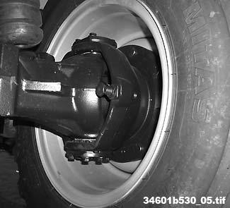
Lubricating the planetary drive bearing
☞ Lubricate grease nipples B on each planetary drive bearing every 50 service hours (or weekly if the machine is used less than 50 hours per week).
Maintenance
Lubricating the loader unit
Lubricate the following points on the loader unit
☞ Lubricate grease nipple C on the tilt cylinder bearing on the frame with grease every 50 service hours (or weekly if the machine is used for less than 50 hours per week). Lubricate daily during heavy-duty operation.
☞ Lubricate grease nipple D on the loader unit bearing every 50 service hours (or weekly if the machine is used for less than 50 hours per week). Lubricate daily during heavy-duty operation.
☞ Lubricate grease nipple E on the lift cylinder bearing on the frame every 50 service hours (or weekly if the machine is used for less than 50 hours per week). Lubricate daily during heavy-duty operation.
☞ Lubricate grease nipple F on the tilt rod bearing every 10 service hours (or weekly if the machine is used for less than 50 hours per week). Lubricate daily during heavy-duty operation.
☞ Lubricate grease nipple G on the tilt cylinder bearing every 50 service hours (or weekly if the machine is used for less than 50 hours per week). Lubricate daily during heavy-duty operation.
☞ Lubricate grease nipple H on the lift cylinder bearing every 50 service hours (or weekly if the machine is used for less than 50 hours per week). Lubricate daily during heavy-duty operation.
☞ Lubricate grease nipple I on the tilt lever bearing every 10 service hours (or weekly if the machine is used for less than 50 hours per week). Lubricate daily during heavy-duty operation.
☞ Lubricate grease nipples K on the quickhitch bearing every 10 service hours (or weekly if the machine is used for less than 50 hours per week). Lubricate daily during heavy-duty operation.
☞ Lubricate grease nipples L on the tilt lever bearing every 10 service hours (or weekly if the machine is used for less than 50 hours per week). Lubricate daily during heavy-duty operation.
Maintenance of Attachments
IMPORTANT!
Correct maintenance and service improves operation and increases the service life of attachments. Follow the lubrication and maintenance instructions in the attachments' operator’s manuals.


Maintenance
Maintenance of the Brake System
Environment!
Use a container to collect brake fluid as it drains and dispose of it in accordance with environmental laws.
Safety instructions
WARNING!
Brakes are critical for safety. Incorrect maintenance or repair may cause brake failure.
• All maintenance and repair work on the brakes must be completed by trained staff.
• The machine operator must complete a daily check of the brake fluid level in the tank.
• An authorized dealer must immediately replace damaged brake lines or hoses – risk of accidents.
Checking/adding brake fluid
The brake fluid tank is located at the front, left side in the cab (next to the brake/inching pedal).
DANGER!
An incorrect brake fluid grade or an insufficient brake fluid level may impair the safety of the brake system –
Accident risk.
☞ Check the brake fluid in the tank regularly.
☞ Fill the brake fluid up to the upper edge of the sight gauge (MAX).

☞ The brake fluid must comply with the SAE specification. –see Fluids and Lubricants on page140
☞ Replace brake fluid every two years.
☞ If the brake system loses a significant amount of fluid continuously, have the system checked and repaired by your dealer.
If the level is below the upper edge of the sight gauge:
☞ Clean the area around the brake fluid filler cap with a clean cloth.
☞ Open tank cover A.
☞ Fill the brake fluid up to upper edge of the sight gauge (MAX).
☞ Close tank cover A.
Tire Care
Tire check
WARNING!
Improper tire repairs present an –Accident risk.
☞ All tire and rim repairs must only be completed by authorized personnel.
☞ All repair work on tires and rims may only be completed by authorized specialist dealers.IMPORTANT!
Regular inspection of the tires: •Improves operating safety, •Increases the service life, and •Can reduce machine downtime.
–see Specifications on page151 for the authorized tire types and the correct tire pressures. Machines are also delivered with a tire table decal on the front window or on the loader unit bulkhead.
Daily check
☞ Complete the following maintenance daily:
• Check tire pressure.
• Check the inside and outside of tires and rims for damage (cracks, aging, etc.).
• Remove objects from the tire tread.
• Remove oil and grease.
Weekly check
☞ Complete the following maintenance weekly:
• Check tires for wear and measure tread depth.