27 minute read
CHECKLISTS


I acknowledge the pre-delivery procedures were performed on this unit as outlined on this page.
Pre-Delivery Checklist
The following checklist is an important reminder of valuable information and inspections that MUST be made before delivering the machine to the customer. Check off each item after the prescribed action is taken.
CHECK THAT:
Unit has not been damaged in shipment. Check for such things as dents and loose or missing parts; correct or replace components as required.
Battery is securely mounted and not cracked. Be sure cable connections are tight.
Cylinders, hoses and fittings are not damaged, leaking or loosely connected.
Filters are not damaged, leaking or loosely secured. Machine is properly lubricated and no grease fittings are missing or damaged.
Hydraulic system reservoir, engine crankcase and drive axles are filled to their proper levels.
All adjustments are made to comply with settings provided in the Maintenance chapter of this manual.
All guards, shields and decals are in place and secured. Model and serial numbers for this unit are recorded in the space provided on this page.
Important
Start the engine and test run the unit while checking that all controls operate properly.
CHECK THAT:
Drive controls and lift arm/bucket/steering controls operate properly and are not damaged or binding.
Drive controls are properly adjusted for correct neutral position.
The parking brake, along with the lock-out devices, are activated with the unit stationary (no pilot control pressure).
All hydraulic functions are NOT operational with the control lever lock in the lock-out position.
Dealership Name
Dealer Representative’s Name
Date Checklist Filled Out
Model & Serial Number
Delivery Checklist
The following checklist is an important reminder of valuable information that MUST be passed on to the customer at the time of delivery. Check off each item as you explain it to the customer.
EXPLAIN:
Safety Instructions and Operation chapters of this manual, regarding the safe operation of this machine.
Maintenance and Troubleshooting chapters for information regarding the proper maintenance of this machine. Explain that regular lubrication and maintenance is required for continued safe operation and long machine life.
A copy of the product warranty is included on the inside front cover of this Operator’s Manual.
Give the Operator’s Manual to the customer and instruct the customer to read and completely understand the contents before operating the unit.
Completely fill out the Owner’s Registration, including customer’s signature and return it to Mustang Manufacturing.
Customer’s Signature
Date Delivered
RETAIN FOR DEALER’S RECORDS
Intentionally Blank
(To be removed as dealer’s file copy)
Operation
Descriptionofcontrols
This chapter describes the indicators and controls in the cab.
The pages listed in the table refer to the description of the controls.
Number/letter combinations describe the controls. For example 40/18 or 40/A means figure number 40/item number 18, or figure number 40/position A.
The following symbols are used: n. s. = not shown.
• This symbol stands for a list.
• Subdivision within lists or an activity. Follow the steps in the recommended sequence.
☞ This symbol requires you to complete the activity described.
➥ This symbol marks the passages in the text describing the effects or results of an activity.
“Option” = optional equipment. Stated whenever components of the machine are installed as an option.
Instrument panel, multifunctional lever and drive lever: overview
Operation
Indicators and warning lights: overview
42 Indicator (red) – engine oil pressure
Comes on if the engine oil pressure is too low. If the oil pressure is to low:
☞ Stop the machine.
☞ Turn off the engine immediately and check the oil level (➠ page 114). Comes on after the ignition is turned on and goes out after the engine is running.
43 Temperature indicator – engine coolant
Indicates if the engine temperature is too high.
35 Indicator (red) – coolant level
Comes on if the coolant level is too low:
☞ Check the coolant system for leaks, have possible damage repaired by an authorized workshop.
☞ Add coolant.
40 Indicator (red) – alternator charge function
Comes on after the ignition is switched on and goes out after the engine runs. Comes on while the engine is running if:
• The V-belt or charging circuit for the alternator is faulty.
• The battery is discharged (➠ page 121).
37 Indicator (green) – right/left turn indicators
Flashes repeatedly when the turn indicators are used.
36 Indicator (green) – right/left turn indicator on rear attachment
Flashes repeatedly:
• When the turn indicators are used.
• If there is an electrical connection to a rear attachment.
44 Indicator (blue) – high beam
Comes on if high beam is turned on or during headlight flashing.
41 Indicator (red) – parking brake
Comes on when parking brake lever 28/ 14 is applied.
39 Hydraulic oil temperature indicator
Comes on if the hydraulic oil temperature exceeds 203°F (95°C).
Risk of hydraulic damage as soon as temperature indicator 39 comes on.
☞ Relieve work and driving hydraulics. To do this:
•Stop the machine.
•Move control lever 28/9 to neutral.
•Select neutral by using tip switch 30/62
•Run the engine at increased speeds until temperature indicator 39 goes out.
38 Indicator (red) – hydraulic oil filter
Indicates too high of pressure in the hydraulic return line to the tank. In this case:
☞ Have the hydraulic oil filter checked and, if necessary, replaced by an authorized dealer.
Operation
Getting Started
Safety instructions
• Only use the steps and handles provided when entering and leaving the cab.
• Face the machine as you enter and leave it.
• Keep the footholds and the handles clean to ensure a safe hold at all times.
• Never use the controls or cables as handles.
• Never climb onto or jump off a moving machine.
• Refer to the load diagrams for the loader unit pallet forks –see Picking up loads with the pallet forks on page106.
Important information
• The machine may only be used in good operating condition in accordance with its designated use and the instructions in the Operator’s Manual, and only by persons who are properly trained and fully aware of the risks involved in operating the machine –see Checklists on page46.
Run-in period
The performance and service life of the machine is heavily dependent on using the machine carefully during its first 100 operating hours.
• Do not overload the machine.
• Do not run the engine at a high speed for extended periods of time.
• Increase the load gradually while varying the engine speed.
• Follow the maintenance schedule –see Maintenance Schedule on page141.
Checklists
Start-up checklist
Operation
Use the checklists in this section to help you check and monitor the machine before, during and after operation.
Complete the checklist below before starting the engine or putting the machine into service:
No. Question ✔
1Sufficient fuel in the tank? (➠ 112)
2Engine oil level OK? (➠ 114)
3Oil level in hydraulic reservoir OK? (➠ 122)
4Water level in washer reservoir OK? (➠ 65)
5V-belt condition and tension checked? (➠ 121)
6Loader unit lubricated? (➠ 127)
7Brake system (including parking brake) OK? (➠ 53)
8Tire condition and inflation pressure OK? (➠ 129)
9Wheel nuts securely tightened (especially after a wheel change)? (➠ 130, 159)
10Lights, signals, indicators, warning lights and indicators OK? (➠ 60, 62, 43)
11Windows, mirrors, lights and steps clean?
12Is the attachment on the loader unit correctly locked? (➠ 83)
13Is the engine cover firmly locked? (➠ 74)
14Especially after cleaning, maintenance or repair work: Rags, tools and other loose objects removed?
15 Approved warning triangle, hazard warning light and first aid kit in the machine?
16Seat position and rearview mirror correctly adjusted? (➠ 66)
16Seat belt fastened? (➠ 69)
Operation
Operation checklist Complete the checklist below after starting the engine, during operation, and when driving on public roads:
No. Question ✔
After starting and during operation:
1Indicators for engine oil pressure and alternator went out? (➠ 43)
2Braking effect sufficient? (➠ 53)
3Temperature indicator for engine coolant in normal range? (➠ 43)
4Steering working properly? (➠ 53)
5Is anyone hazardously close to the machine? (➠ 17)
6 3rd control circuit locked? (➠ 81)
When driving on public roads:
7Bucket and attachments in the transport position? (➠ 52)
8 Transport locks installed? (➠ 80)
9Control lever for lift and tilt hydraulics of the loader unit locked with the lock? (➠ 52)
Parking checklist Complete the checklist below when parking the machine:
No. Question ✔
When parking:
1Attachments on the loader unit lowered to the ground? (➠ 59, 80)
2Parking brake applied? (➠ 56)
3Machine cab locked (especially if the machine cannot be supervised)? (➠ 70)
When parking on public roads:
4Machine adequately secured? (➠ 59)
When parking on uphill and downhill gradients:
5Machine additionally secured with chocks under the tires to prevent it from rolling away? (➠ 59)
Battery Disconnect Switch
The battery master switch is located in the engine compartment next to the battery.
Interruptingpowersupply:
☞ Turn and remove the key of the battery master switch (notched position).
Switchingonpowersupply:
☞ Insert the key in the battery master switch.
☞ Turn the key to the notched position.
Starting the engine
Before starting the engine
General
0
☞ Complete the Start-up checklist on page 46
☞ Switch on the battery disconnect switch (if required).
☞ Adjust seat position and rearview mirror.
CAUTION!
All controls must be within easy reach. The operator must be able to fully move the brake and accelerator pedals.
☞ Fasten the seat belt.
☞ Make sure that:
•Parking brake (28/14) is engaged.
•Control lever (28/9) for the loader unit is in neutral.
IMPORTANT!
You MUST apply parking brake (fig. 28/14) to start the engine. Do NOT run the starter for more than 10 seconds continuously. If the engine does not start, wait for about one minute to let the battery recover before trying again.
IMPORTANT!
You cannot start the engine by towing the machine, because there is no driving connection between the engine and gearbox when the engine is off.
• You cannot actuate the starter if the engine is already running (start repeat interlock).
Starting the engine
After completing the instructions –see Before starting the engine on page49:
☞ Insert the ignition key in preheating/start switch 24/ 14
☞ Turn the ignition key to position “1”.
☞ Check whether the following indicators come on:
• 25/ 45 for the engine oil pressure.
• 25/ 43 for the alternator charge function.
• 25/ 44 if the parking brake is applied.
IMPORTANT!
If any of the above indicators do NOT come on, they may have failed and should be replaced immediately.
☞ Turn the ignition key to position “2” and hold it in this position for about 5 seconds. The oil pressure, alternator charge and parking brake indicators should be on.
➥ The intake air is preheated.
☞ Press accelerator pedal 28/6 down about 1/4 of full travel.
☞ Turn the ignition key to position “3” and hold it in this position until the engine starts.
☞ Release the ignition key.
Starting at low temperatures
☞ Turn the ignition key to position “2” hold it in this position for about 15 seconds.
☞ Press accelerator pedal 28/6 all the way down.
☞ Turn the ignition key to position “3” and hold it in this position until the engine starts.
☞ Release the ignition key.
When the engine runs smoothly (increased engine speed):
☞ Release accelerator pedal 28/6
IMPORTANT!
In general, a battery delivers less energy in cold conditions. Therefore, make sure the battery is always well charged.
After the engine has started
☞ Check that indicators 25/43 and 25/45 have gone out:
☞ Let the engine idle for about 2 minutes. Incold(winter-type)weather
☞ Increase the engine speed slowly.
☞ Do NOT run the engine at full load until it has reached operating temperature.
Jump-starting the engine
Safety instructions
DANGER!
Never jump-start the engine if the discharged battery is frozen, because there is a risk of explosion. Replace the battery. The machines must not touch when jump-starting because when both machines are connected by jump leads, there is a risk of sparking.
• The external power source must deliver 12 volts. Supply voltages higher than 12V will damage the electrical systems of both machines.
• Only use authorized jumper cables that are in good condition.
IMPORTANT!
The jumper cable connected to the positive (+) terminal of the starting battery must never touch electrically conductive machine parts, because there is a risk of short circuit.
• Route the jumper cables so that they cannot catch on rotating components in the engine.
Procedure
☞ Start the engine of the jump-starting machine.
☞ Connect one end of the red positive (+) jumper cable to the positive (+) terminal of the dead battery, then connect the other end to the positive (+) terminal of the starting battery.
☞ Connect one end of the black negative (–) jumper cable to the negative (–) terminal of the starting battery.
12 V 12 V 34001b710_05.eps
☞ Clip the other end of the black negative (–) jumper cable onto the engine block.
DANGER!
DO NOT connect the other end of the jump lead to the negative terminal of the dead battery, because gas emerging from the battery may ignite if sparks are formed.
☞ Start the engine of the machine with the dead battery.
After the engine has started:
☞ While the engine is running, disconnect both jumper cables in exactly the reverse order (first the negative (–) terminal, then the positive (+) terminal to avoid sparking near the battery.
Operation
Before driving the machine
Special instructions for public roads • Follow these instructions –see Use: attachment on page9.
☞ Carry out a functional check of:
• Brakes
• Steering
• Lights
☞ Empty the bucket.
–see Control lever (joystick) on page80.
☞ Tilt back the bucket 27/B
☞ Raise the loader unit so that both red marks 28/D on the lift frame and the bulkhead are aligned.
IMPORTANT!
Ground clearance for transport27/C is about 10” (250mm) with the standard bucket, standard tires, and marks28/D aligned.
Control lever lock: loader unit and 3rd control circuit
DANGER!
Secure control lever 29/8 (joystick) and control lever 29/9 (3rd control circuit) against unintentional actuation when driving on public roads. If the control levers are not secured –

Accident risk.
☞ Push control lever 29/8 down vertically in neutral position .
➥ The control lever is locked in this position and can no longer be moved.
☞ Unscrew lock sleeve A of control lever 29/9 clockwise until it is pulled down by spring action.
☞ Let control lever 29/9 engage in center position .
➥ The control lever is locked in this position and can no longer be moved.

Inspection and adjustment of important functional units
Steering
☞ Functional check: Move the steering wheel to the left and right.
IMPORTANT!
The power steering system is only operational when the engine is running. But if the engine or hydraulic steering fails (e.g., failure of the pump drive), the machine can still be steered.
CAUTION!
If the power steering fails, turning the steering wheel requires greater effort. Take this into account especially when towing the machine.
☞ Adapt towing speed to the steering.
☞ Use a tow bar.
Wheel synchronization position
IMPORTANT!
The machine has self-synchronizing axles. If you notice that the wheels on the axles do NOT run in the same track –see Synchronizing the steering system on page58.
Service brake/inching pedal
The rear brake lights do not come on when you:
•Brake by applying the parking brake.
•Brake hydrostatically with the drive.
☞ Only pressing brake/inching pedal 28/ 31 causes the brake lights to come on.
WARNING!
Dirt accumulating around the brake pedal can result in brake malfunctions–Accident risk.
☞ Always keep brake/inching pedal 28/31 clean.
☞ Before driving the machine, press brake/inching pedal 28/31 down and check:
• For resistance after pressing the pedal down to about 50% of its maximum travel.
• If the brake lights come on after you press the brake pedal down.
☞ For resistance after pressing the pedal down at a low speed.
Operation
WARNING !
Pressing brake/inching pedal 28/ 31 down slightly causes the inching valve to respond; the inching valve does NOT effectively brake the machine –
Accident risk.
☞ Press brake/inching pedal 28/31 down to its maximum power.
Driving
IMPORTANT!
You can only move the machine after releasing parking brake 28/14.
After starting the engine:
☞ Release parking brake 28/14
☞ Select the driving direction by using toggle switch 33/59 on the control lever.
➥ Indicator 30/59 or 30/61 comes on.
☞ Gradually press down accelerator pedal 28/6
➥ Machine travels.
IMPORTANT!
The engine will NOT start unless the parking brake is applied and the indicator is on.
Accelerator pedal
Accelerator pedal 28/6 controls the drive speed as follows:
• Press accelerator pedal down. ➥ Drive speed is increased.
• Release accelerator pedal slowly. ➥ Drive speed is reduced.
• Release accelerator pedal fully.
➥ Hydrostatic braking.
Speed depends on the drive range selected with rocker switch 34/67
Brake/inching pedal
WARNING!
Dirt accumulation in the area of the brake can result in brake malfunctions –Accident risk.
☞ Always keep brake/inching pedal 28/31 clean.
Use the brake/inching pedal to brake the machine regardless of the speed range setting and position of the accelerator pedal.
When you inch the brake pedal (pedal pressed in slightly), the pedal can be used like a car’s clutch. The drive system is no longer supplied with hydraulic oil, which means the entire engine output is available to the work hydraulics. This allows you to raise the loader unit rapidly.
☞ Before driving the machine, press brake/inching pedal 28/31 down and check for:
• Resistance after pressing the brake pedal down to about 50% of its maximum travel
• The brake lights come on after you press the pedal down
• Traffic in the rearview mirror
• For resistance after pressing the pedal down at a low speed
WARNING!
Pressing the brake/inching pedal down slightly causes only the inching valve to respond; the inching valve does NOT effectively brake the machineAccident risk.
☞ Press brake/inching pedal down to its maximum travel until the braking effect is felt.
Braking
☞ Press brake/inching pedal 28/31 down with force
Inching
☞ Press brake/inching pedal 28/ 31 down slightly
Operation
Parking brake
IMPORTANT!
You cannot drive the machine unless parking brake 31/13 is released.
Function
• Prevents the machine from rolling away (use on sloped surfaces only).


• Emergency brake (only use if the service brake fails).
WARNING!
Only use parking brake 31/13 instead of the service brake if the service brake fails. When you use parking brake 31/13, the brake lights do not light up, and the machine brakes abruptly –
Accident risk.
Prevent rolling away
☞ Pull lever 32/13 up into the top notch. ➥ Indicator 23/41 comes on.
➥ Neutral is activated.
Release the parking brake
☞ Pull up lever 32/13 slightly.
☞ Press button A
☞ Move lever 32/13 all the way down.
Changing direction
WARNING!
Changing direction at high speed and full throttle causes the machine to stop abruptly.
☞ Slow the machine to walking speed before changing direction.
☞ Reduce engine speed: remove your foot from the accelerator pedal.
☞ Slow the machine to walking speed.
☞ Select a new driving direction with switch 33/59:
FunctionOperationEffect
Selecting a speed range
The machine has two travel speed ranges.
☞ Set driving direction to neutral with tip switch 34/61 on the joystick.
☞ Press switch 34/52 to the required speed range.
➥ Indicator in switch comes on.
SymbolMeaningRecommended
Work range A
➥ 0–4 mph (0–6 kph) 12 mph (20kph)
Speed range B = 0–12 mph (0–20 kph)
IMPORTANT!
Used for work involving short loading cycles, i.e., a rapid succession of loading and unloading operations, e.g., onto a truck, and for work requiring precise speed adjustment, e.g., rotary broom applications.
For long-haul travel
You can only move the machine after releasing parking brake 31/13
☞ Release the parking brake 31/13
☞ Select the driving direction with switch 34/61 on the control lever.
☞ Gradually press accelerator pedal 28/6
☞ Test the brakes at low speed.
Backup warning system
The backup warning system consists of backup alarm A, fitted onto the inside of the towing device cover, and a switch and wiring. The backup alarm generates an acoustic signal when you shift into reverse. The acoustic level is about 103dB(A) at a distance of 3’ (1 m) and at a frequency of 2800Hz.
WARNING!
When backing up with the machine –Accident risk.
☞ Make sure nobody is within the work area of the machine.
☞ Do not rely exclusively on the backup alarm to alert others.
Operation Differential Lock
IMPORTANT!
The differential lock neutralizes the compensating effect of the differential, i.e., traction is distributed evenly to the front and rear wheels.
•Both the front and the rear axle of the machine are fitted with a self-locking differential.
•The lock value is 45% for each axle. Differential lock control is optional. Without the optional differential lock control, the differential is locked automatically and cannot be switched on or off by the operator.
Switchingthedifferentiallockonandoff(option)
IMPORTANT!
To prevent damage, the differential lock can only be switched on using tip switch 73 when the brake/inching pedal is engaged.
IMPORTANT!
The differential lock tip switch 73 may be located on either the right or the left on the joystick.
Switchingonthedifferentiallock
☞ Stop the machine.
☞ Press and hold tip switch 73 on the joystick.
☞ Press and hold the brake/inching pedal for 3 – 5 seconds.
➥ indicator 72 in the side console (next to the instrument panel) illuminates and the differential lock is switched on.
☞ Carefully release the brake/inching pedal with tip switch 73 pressed. Switchingoffthedifferentiallock
☞ Reduce engine speed.
☞ Release tip switch 73.
Indicator 72 on the instrument panel goes out and the differential lock is switched off.
Steering System
Synchronizing the steering system
WARNING!
DO NOT synchronize the steering system as you drive on public roads –Accident risk.
☞ Synchronize the steering system as described below before driving on public roads.
If the wheels on both axles are not running in the same track:
☞ Drive at a slow speed, turn the steering wheel slowly to the left and right as far as it will go. Repeat.
☞ Quickly turn the steering wheel back to the straight-ahead position.
☞ Contact your Mustang dealer if this does not synchronize the wheels.
Stopping the Machine
☞ To stop the machine, follow the Mandatory Safety Shutdown Procedure –see Mandatory Safety Shutdown Procedure on page18
Parking the Machine
WARNING!
Machines parked on slopes may roll away. If you park on a slope, park across the slope if possible and:
☞ Apply the parking brake.
–see Parking brake on page56.
☞ Place chocks under the downhill sides of the tires.
☞ Perform the Mandatory Safety Shutdown Procedure –see Mandatory Safety Shutdown Procedure on page18
Afteroperationatfullpower
☞ Allow the engine to run until the temperature stabilizes.
☞ Turn off the engine. To do this:
• Turn the ignition key to position “0.” Wait for all movement to stop.
• Remove the ignition key and take it with you.
Operation
Light System
6243
The switch panel for the light system is located on the left on the instrument panel
Parkinglights ON ☞ Press switch 62 to the 1stpositionB
➥ Indicator in switch comes on OFF
☞ Press switch 62 down to positionA
Lowbeam ON
➥ Indicator in switchgoes out
34200b0312.eps 28
☞ Press switch 62 to the 2ndpositionB
☞ Move lever 28 to position II
➥ Indicator in switch comes on OFF
☞ Press switch 62 down to positionA
IMPORTANT!
➥ Indicator in switchgoes out
Turn off the parking light by turning the ignition switch 30/14 to position 0
Highbeam ON
☞ Press switch 62 to the 2ndpositionB
☞ Move lever 28 to position I
☞ Move lever 28 to position II
Headlightflasher ON
☞ Briefly pull lever 28 fully up (beyond positionII)
➥ Indicator (blue) 43 goes out
➥ Indicator (blue) 43 comes on OFF
➥ Low beam comes on
➥ Indicator (blue) 43 comes on
Work lights
6866
WARNING!
The work lights may momentary blind motorists on public roads.

☞ Do not switch on the work lights when driving on public roads.
Frontand/orrearworkinglights(option)
ON ☞ Press switch 68 to position B ➥ Indicator in switch comes on OFF ☞ Press switch 68 to position A ➥ Indicator in switch goes out
2frontworkinglights(option)
ON ☞ Press switch 68 to position B ➥ Indicator in switch comes on OFF ☞ Push switch 68 to position A ➥ Indicator in switch goes out
2rearworkinglights(option)
ON ☞ Press tip switch 66 briefly ➥ Indicator in tip switch comes on OFF ☞ Press tip switch 66 briefly ➥ Indicator in tip switch goes out
Interiorlight
Interiorlight
ON ☞ Press switch 2 to the left or right OFF ☞ Move switch 2 to center position
Signalling System
➥ Indicator 35 flashes during trailer operation.
CAUTION!
The turn indicator is not in working order if indicator 36 flashes about twice as fast as normal.
☞ Check the front and rear indicators immediately. ➥ Have the turn indicator system repaired if necessary.
➥ The Indicator in the switch and Indicator 36 on the instrument panel flashes
➥ The Indicator in the switch and Indicator 36 on the instrument panel goes out
Rotating beacon (option)
IMPORTANT!
Local regulations may prohibit rotating beacon use on public roads except under certain conditions, such as, if the road is within the machine's working range and the machine represents an obstruction to the normal flow of traffic.

Rotating beacon (option)
ON
Cab heating and ventilation
IMPORTANT!
The heater can be set to two operating conditions:
•Ventilation, fresh air
•Heating
The air flow is directed to the front window via defroster vents, and to the floor area via the floor vents. The floor vents can be closed and adjusted separately.
Operation
AirConditioning Airconditioningoperation
In warm weather, the air conditioning system supplies cool and dehumidified air to the cab via the vent nozzles in the cab roof.
IMPORTANT! Close the door and the windows to achi eve the best air conditioning results.
The rotary switch for the air conditioning system is located on the left next to the operator’s seat.
AirconditioningoperationCooling
Turn rotary switch 25 to range 1Low
Turn rotary switch 25 to range 2Medium
Turn rotary switch 25 to range 3High
Turn rotary switch 25 to range 0OFF
IMPORTANT!
The heating and ventilation system can be used along with the air conditioning.
• –see Cab heating and ventilation on page63.
CAUTION!
To prevent malfunctioning of the air conditioning system and possible loss of coolant:
☞ Run the air conditioning system once a month.
•This prevents the seals in the compressor from drying and becoming brittle.

☞ Check V-belt tension and clean the condenser.
• –see Air Conditioning Maintenance on page132.
☞ The air conditioning system must be repaired, serviced and filled with a refrigerating agent only by trained staff and an authorised workshop.
Windshield washer system
Frontwindowwiper
28Washerpumpforfrontandrearwindow
Tankforwindshieldwashersystem
Tank filler inlet 31 is located at the front inside of the cab, on the left.


IMPORTANT!
Fill the windshield washer system with clean tap water only. Add a cleaning agent if required. In winter, add antifreeze to the water. For further information on concentrations –see Fluids and Lubricants on page140.
Operation
Operator's Seat
Seatadjustment
Always adjust the seat to your individual needs. This will help avoid or minimize physical disorders related to bad posture.
WARNING!
Never change the seat position when driving or working –
Accident risk.
☞ Adjust the seat before moving the machine.
☞ Make sure the levers for seat adjustment are safely engaged.
The seat can be set to the following positions:
• b= weight adjustment a with weight indication.
• c= height adjustment.
• d= armrest inclination.
• e= backrest adjustment (depending on version).

• f= horizontal adjustment.
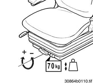
Weightadjustment
IMPORTANT!
Adjust the seat suspension correctly to ensure a high level of ride comfort, and to avoid or minimize physical disorders related to bad posture. Use lever a to adjust the seat suspension to the operator's weight. The weight indicator b shows the set operator weight in kilograms.
☞ Sit in the seat.
To adjust for a heavier operator weight:
☞ Turn lever a clockwise.
To adjust for a lighter operator weight:
☞ Turn lever a counter-clockwise.
Heightadjustment
Up:
☞ Raise seat as required. The seat locks clicks at the detents as the seat is raised.
Down:
☞ Raise seat as far as possible and lower seat to the lowest position.
Backrestadjustment
☞ Sit in the seat.
☞ Pull lever e up and lean back to push the backrest into the required position.

☞ Release lever e to lock the backrest in position.
Horizontaladjustment
☞ Sit in the seat.
☞ Pull lever f up and move the seat forward or rearward as required.

☞ Release lever f to lock the seat in position.

Operation
Armrestadjustment
The armrest can be folded back as required. Adjust the armrest as follows:

Up:
☞ Turn handwheel g clockwise as required.
Down:
☞ Turn handwheel g counter-clockwise as required.
Seat belt
WARNING!
Do not drive or work without the seat belt fastened –Risk of personal injury.
☞ Buckle up before moving or working with the machine.
•Seat belt must not be twisted.
•Seat belt must run over the hips, not over the stomach, and must always be applied tightly.
•Do not place seat belt over hard-edged or fragile items (tools, metal ruler, glasses, pen) carried inside your clothes.
•Never buckle up two persons using one seat belt.
•Check seat belt regularly. Have damaged parts immediately replaced by an authorized dealer.
•Always keep seat belt clean.
•Make sure the seat belt buckle is not obstructed by anything, such as paper or clothing, which may prevent the latch from locking properly. After an accident, the seat belt strap is stretched and is no longer serviceable. In another accident the same strap –Will not provide adequate protection.
☞ Replace the seat belt strap after an accident.
☞ Have fastening points and seat fixture checked for bearing capacity.
Seat belt 24 is designed for the operator's safety during work on construction sites and road travel.
Fastening the seat belt
☞ Fasten seat belt 24 as follows before moving the machine:
• Hold the belt at buckle latch A and run it slowly and steadily over the hips to buckle B
• Insert buckle latch A into buckle B until it engages audibly (pulltest).
• Tighten seat belt by pulling at its end.
➥The seat belt must always be tightly in place over the hips.
Unfastening the seat belt
☞ Unfasten seat belt 24 as follows:
• Hold the seat belt.
• Press red button C on buckle B
➥Latch A is released from buckle B by spring action.
• Slowly return the seat belt to the retractor.
Lengthen/shorten seat belt setting
☞ Lengthen the seat belt as follows:
• Hold buckle latch A at a right angle to the seat belt and pull the seat belt to the required length.
☞ Shorten the seat belt by pulling the free end D of the belt.
IMPORTANT!
When pulled slowly, the automatic seat belt allows full freedom of movement. However, it locks during abrupt braking and may also lock when driving over potholes or uneven terrain.
Operation
Doors
WARNING!
Close the doors when driving and working with the machine –Accident risk.


☞ Close the doors before moving the machine.
Openingthedoorfromtheoutside:
☞ Press button A
Locking/Unlockingthedoor:
☞ Lock/unlock the door with the ignition key. Turn the key clockwise to lock; counter-clockwise to unlock.

Openingthedoorfromtheoutside
☞ Press button A
Openingthedoorfromtheinside
☞ Pull handle B up.
IMPORTANT!
Enter and exit the cab by using the left door. In case of an emergency the right side window may be used as emergency exit. –see Emergency exit – side window on page73.
Securing an open door
☞ Press the door against the bracket of arrester 18 until it locks in the arrester with a click.
IMPORTANT!
Lubricate latch 11 weekly.
Releasinganopendoor
☞ Press button B on the door arrester forward.
➥ The door is released from the arrester.

Operation
SideWindow
WARNING!
Lock the side window when driving the machine. If the side window is not locked –


Crushing risk.
☞ Make sure the side window is locked in place when either opened or closed.
☞ Make sure the open side window is engaged in the arrester. –see Locking the open side window on page73.
Closingthesidewindow
☞ Turn lever A down.
Openingthesidewindow
☞ Turn lever A up.
Openingthesidewindow
☞ Turn lever A up.
☞ Push lever A horizontally to the outside.
☞ To fasten the window in its final position: Press the end of lever a downward until it is firmly seated in guide b.
Fullyopeningthesidewindow
☞ Turn lever A up.
☞ Push lever A horizontally to the outside.
☞ In order to completely swing the window outward: Pull the end of lever a to the rear through and out of guide b
Operation
Lockingtheopensidewindow
☞ Open the side window completely and press it against the arrester until it locks in place with a click.
➥ The side window locks into the open position.
IMPORTANT!
Lubricate the arrester at regular intervals.
Unlockingtheopensidewindow
The side window can be unlocked from the inside only.
☞ Press the push button (at the rear right in the cab).
➥ Side window is released by spring action.
☞ Close the side window.
Emergencyexit–sidewindow
In the case of an emergency, the side window can be used to exit from the cab if the door can no longer be used.

WARNING!
The right side of the machine does not have foot or hand holds that ensure safe access/exit. In addition, with the side window unlocked –

Crushing risk.
☞ Do not use the side window as access or exit except for emergency situations.
☞ Before resuming normal service, lock the window lock lever back into place in the guide.
–see Closing the side window on page72.
Operation
Engine cover
Opening
☞ Press lock A.
☞ Pull the engine cover upward.
Closing
☞ Firmly press down the engine cover until A it locks with a click.
Lockingandunlocking
Lock the engine cover with the ignition switch key.
TowingtheMachine Safetyinstructionsfortowing
If the engine and/or the hydraulic drive stop functioning, the machine can be towed under the following conditions:
•Tow the machine with a tow bar only. The brake and steering systems hydraulic assists are not activated if the engine and/or the hydraulic systems are not functioning.
•Make sure nobody is dangerously close to the tow bar.

•The machine may only be towed using suitable tow equipment (towing bar) in connection with suitable towing apparatus, such as a tow coupling, hooks and eyes.
•Tow the machine slowly and cautiously.
DANGER!
Careful when towing the wheel loaderAccident risk.
☞ The towing vehicle must have enough tractive power and be fitted with a safe brake system.
☞ Only tow with a tow bar.
➥ –see Specifications on page151 for the machine's dimensions and weights.
☞ Eye hooks for towing the machine –see Machine overview on page7.
☞ If possible, run the engine at idling speed when towing the machine.
➥ Turning the steering wheel requires greater effort if the diesel engine and the brakes fail.
☞ Tow the machine from the area only after you have opened the HP pressure relief valves on the variable-displacement pump.
➥ Tow the machine out of the area only at walking speed and only over short distances.
Towingpreparation
Disablingthevariable-displacementdrivepump
IMPORTANT!
The hydrostatic power train can be damaged when towing the machine.
☞ Tow the machine only after you have opened the HP pressure relief valves.
☞ Tow the machine only at walking speed and only over short distances.
☞ Stop the engine.
☞ Turn off the ignition and remove the ignition key.
Variable-displacement12mph(20kph)drivepump
☞ Switch over the HP pressure relief valves A on the variable-displacement pump. To do this:
• Loosen lock nuts B on both HP valves A.
• Tighten screws C on both HP valves A until they are flush with lock nuts B.
• Secure screws C on both HP valves A with lock nuts B.
Aftertowing
Enablingthevariable-displacement12mph(20kph)drivepump
☞ Switch over the HP pressure relief valves A on the variable-displacement pump. To do this:
• Loosen locknuts B on both HP valves A.
• Loosen screws C on both HP valves A as far as they will go and secure them with locknuts B
Operation
CraneHandlingtheMachine
Safetyinstructionsregardingcranehandling
•The crane and the lifting gear must be adjusted to the proper dimensions.
➥ –see Specifications on page151.
•Crane handling requires lifting gear of four equal lengths.
•Secure the machine against unintentional movement!
DANGER!
Incorrect crane handling of the machineAccident risk.
☞ Make sure nobody is in the machine.
☞ Have loads fastened and crane operators instructed by experienced persons only. The person giving the instructions to the crane operator must be within sight or sound of the crane operator.
☞ Make sure the crane and the lifting gear (cables, chains) have sufficient loadbearing capacity.
☞ Load the machine only with the standard bucket empty and in transport position.
☞ Keep clear of suspended loads.
☞ It is essential to read the safety instructions in this manual –see Safety on page17
Cranehandlingthemachine
☞ Load the machine as follows:
• Empty the standard bucket.
• Mount and safely lock the standard bucket –see Installing attachments on page83.
• Set the drive to neutral –see Changing direction on page56.
• Tilt the standard bucket back and lower it to the transport position.
• Engage the parking brake –see Parking brake on page56.
• Turn off the engine and remove the ignition key.
• Do not allow anyone to stay in the cab.
• Close the doors and the engine cover.
• Fasten the loader to the crane at the four lifting points –see Machine overview on page7.
CAUTION!
Do not use the eye hooks on the cab to crane lift the machine.
• Carefully raise the machine.
LoadingandTransportingtheMachineonaTransportVehicle Generalsafetyinstructions
•The transport vehicle must be of adequate size - see “Weights” on page 158 for the dimensions and weights of the machine.
•Remove any mud, snow or ice from the tires so the machine can be safely driven onto the ramps.
•Secure the machine against unintentional movement.
•When positioning the machine on the transport platform, make sure the machine is at the lowest possible position and that the center of gravity of the load is on the center line of the transport vehicle, if possible.
•Do not exceed the transport vehicle’s gross weight rating and the gross axle weight rating when loading and transporting the machine.
•Make sure the load does not fall short of the minimum axle load of the steering axle, otherwise the transport vehicle’s steering could be seriously affected.
•Distribute partial loads to ensure even load on all axles.
•Secure the load properly so it cannot slip, slide, roll, tip over or fall, or cause the transport vehicle to tip over under usual transport conditions. Use anti-slip bases and linings, loadsecuring straps and chains, clamping beams, protective paddings, nets, edge protectors, etc. as required to properly secure the load.
•Transport conditions to be considered as possibilities are conditions where the brakes are slammed on, evasive maneuvers are performed with the transport vehicle, and transport on uneven roadways.
•Depending on the load, adjust transport speed to the road and traffic conditions and to the handling of the transport vehicle.
•Always use the proper tie-down points when using straps and chains –see Machine overview on page7.