5 minute read
Operation


Loadingandtyingdownthemachine
DANGER!
The machine must be loaded and transported properlyAccident risk.
☞ It is essential to read and follow the safety instructions in this manual –see Safety on page17
☞ Load as follows:
• Secure the transport vehicle tires with chocks to prevent it from rolling.
• Place the access ramps at the smallest possible angle. Do not exceed an angleof20°. Only use access ramps with an anti-skid surface.
• Make sure the loading area is clear and access to it is not obstructed.
• Make sure the access ramps and the wheels of the machine are free of oil, grease, snow, ice, etc.
• Start the engine of the machine.
• Raise the bucket enough so that it will not touch the access ramps.
• Carefully drive the loader onto the middle of the transport vehicle.
• Set the drive to neutral –see Changing direction on page56.
• Lower the bucket onto the loading area.
• Stop the engine.
• Apply the parking brake –see Parking brake on page56.
• Remove the ignition key.
• Do not allow anyone to stay in the cab.
• Close the doors and the engine cover.
☞ Tie down the machine as follows:
• Make sure the authorized maximum height is not exceeded.
• Secure all tires of the wheel loader with chocks in front of and behind each wheel.
• Securely strap the machine down at the eye hooks –see Machine overview on page7 – with sufficiently dimensioned belts or chains onto the platform.
• Before transporting the machine through heavy rain, close the outlet of the muffler with a cap or suitable adhesive tape.
34001b330_02.eps
• Make sure the driver of the transport vehicle knows the overall height, width and weight of the vehicle, including the loaded machine, before starting transport.
• Know and follow the legal transport regulations for the area in which the transport will occur.
34001b330_17.eps
Working with the Machine
General safety instructions
• Never drive up to the edge of a pit from the outside – risk of cave-in.
• Never undermine the foundations of walls – risk of collapse.
• When excavating, look out for high-voltage and underground cables, and gas and water pipes.
• When using lifting accessories such as pallet forks, comply with the load diagrams –see Picking up loads with the pallet forks on page106.
• The hydraulic system of the machine is still pressurized even when the engine is not running. Depressurize the sections of the system and hydraulic lines that you want to open before starting setup or repair work (e.g., fitting/removing an attachment with hydraulic functions) –see Depressurizing the quick-couplers on the loader unit on page82
Operation
Controllever(joystick)
Control lever for lift and tilt cylinder hydraulics
DANGER!
Unintentional operation of control lever 9 when driving on public roads: Accident risk.
☞ Lock the control lever 76/9 –see Control lever lock (joystick) on page80.
•
•
•
•
Control lever lock (joystick)
•
IMPORTANT!
The control valve is equipped with a float position. This helps when working with a rotary broom, snowplow, and grading in reverse.
Complete the following procedures to turn on the float position:
☞ Push control lever 9 fully forward to final position D.
The lock lever for locking the control lever is located on the control lever base console.
Lockingthecontrollever
☞ Put the control lever 9 into the neutral position and push it down vertically
➥ The control lever is locked in this position and cannot be moved.
➥ Follow these instructions:
–see Before driving the machine on page52
Unlockingthecontrollever
☞ Pull up on the control lever to unlock.
Operation of 3rd control circuit
WARNING!
When working with attachments without a hydraulic function, operating the 3rd control circuit 10 unlocks the quickhitch –
Risk of personal injury.
☞ Lock control lever 10 (3rd control circuit) when working with an attachment. –see Operation of 3rd control circuit on page81.
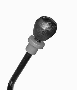
☞ To unlock control lever 10:
• Pull lock sleeve A upward and rotate it counter-clockwise.
☞ To briefly unlock control lever 10 :
• Pull lock sleeve A upward and hold.
☞ Push the control lever 10 forward:
➥ The attachment on the quickhitch is unlocked. Attachmentswithhydraulicfunctions
➥ Pushing the control lever forward O operates hydraulic attachment functions, such as closing the multipurpose bucket.


☞ Pull the control lever C to the rear
➥ The attachment on the quickhitch is locked.
➥ Pulling the control lever to the rear C operates hydraulic attachment functions, such as opening the multipurpose bucket.
3rdcontrolcircuitcontinuousoperation
IMPORTANT!
3rd control circuit continuous operation is useful when using attachments with additional hydraulic functions, or when operating hydraulic motors (e.g., rotary broom) or attachments with separate control valves.
3rd control circuit continuous operation is controlled with the control lever.
☞ Pull control lever 10 to the rear C.
☞ Unscrew lock sleeve A clockwise until it is pulled down by spring action and engage control lever 10 in position C.
➥ The control lever is locked in this position and cannot be moved.
Operation
Lowering the loader unit with the engine turned off
Lower the loader unit as follows:
☞ Make sure no one is near the machine.
☞ Push and hold control lever 9 forward C.
➥ Until the loader unit is completely lowered.
☞ Return control lever 9 to neutral.
Depressurizing the quick-couplers on the loader unit
IMPORTANT!
The hydraulic system of the machine is still pressurized even when the engine is not running. The hydraulic quick-couplers can be released, but they cannot be re-attached because the hydraulic lines are pressurized. Therefore:

☞ Depressurize the sections of the system and hydraulic lines that you want to open before starting setup or repair work (e.g., fitting/removing an attachment).
Depressurize as follows:
☞ Engage the parking brake.
➥ –see Parking brake on page56.
☞ Unlock the 3rd control circuit.
➥ –see Operation of 3rd control circuit on page81.
☞ Turn off the engine.
➥ Do not turn off the ignition.
☞ Move control lever 10 back and forth several times O/C
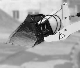
Installing attachments
Installing the standard bucket is described below. If you are fitting or removing attachments with their own hydraulic functions, you must follow the information provided in the Operator’s Manual of the attachment.
Fitting attachments onto the quickhitch WARNING!
The attachment must always be locked onto the quickhitch –Accident risk.
☞ Before working, be sure that the attachment is locked onto the quickhitch by using the lock cylinder. Be sure that you can see the lock pins on both sides of the mounting holes on the attachment.

Install as follows:
☞ Drive the machine up to the attachment.
☞ Lower loader unit E by pushing control lever 10 forward C.
☞ Tilt the quickhitch forward by pushing control lever 10 to the right B.
☞ Adjust the height of pin shanks G of the quickhitch so that they are under catch hooks F of the attachment.
☞ Drive the machine forward until pin shanks G of the quickhitch are directly beneath the catch hooks of attachment F.
☞ Raise loader unit E until pin shanks G engage in pin shanks F of the attachment. To do this: Pull control lever 10 rearward D
☞ Fully tilt back the quickhitch. To do this: Push control lever 10 to the left A.