3 minute read
4.3.3 Control panel

4.3.3 Control panel
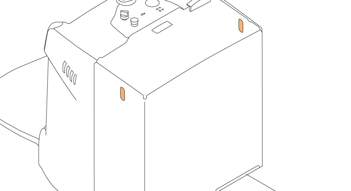
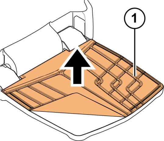
Figure 5. Control panel
1. Emergency stop button 2. Key switch 3. Truck display
4.3.3.1 Emergency stop button
Press the emergency stop button to disconnect the truck's power supply. Release the button by turning it clockwise.
Use the emergency stop button in the following cases:
• In case of a short circuit or some other electrical malfunction (for example, if the pump motor does not stop running). • In case of an accident.
© Mitsubishi Forklift Trucks 2013. All rights reserved. Revision: C Document ID: 615026 19 (214)
4.3.3.2 Key switch
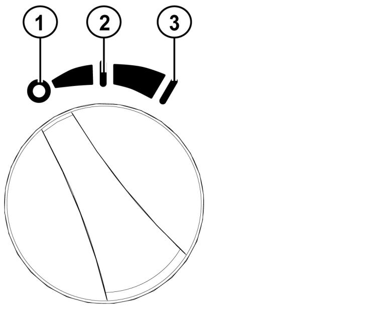
Figure 6. Key switch
1. Power off 2. Power on, economy mode 3. Power on, standard mode
The key switch switches the truck's electrical system on and off.
When the key switch is in the off position, the truck’s electrical system is turned off. Note however that power may be still connected to certain electronic devices.
When the key switch is turned once to the right, the truck’s electrical system is turned on and the economy mode (lower energy consumption and deceleration, maximum speed limited to 6 km/h) is activated. The ECO symbol is shown in the multi-function display.
When the key switch is turned once more to the right, the standard mode (normal energy consumption and deceleration, maximum speed 6 km/h) is activated.
© Mitsubishi Forklift Trucks 2013. All rights reserved. Revision: C Document ID: 615026 20 (214)
4.3.3.3 Truck display
There are two display versions available:
• LED display (standard) • Multi-function display (alternative)
LED display
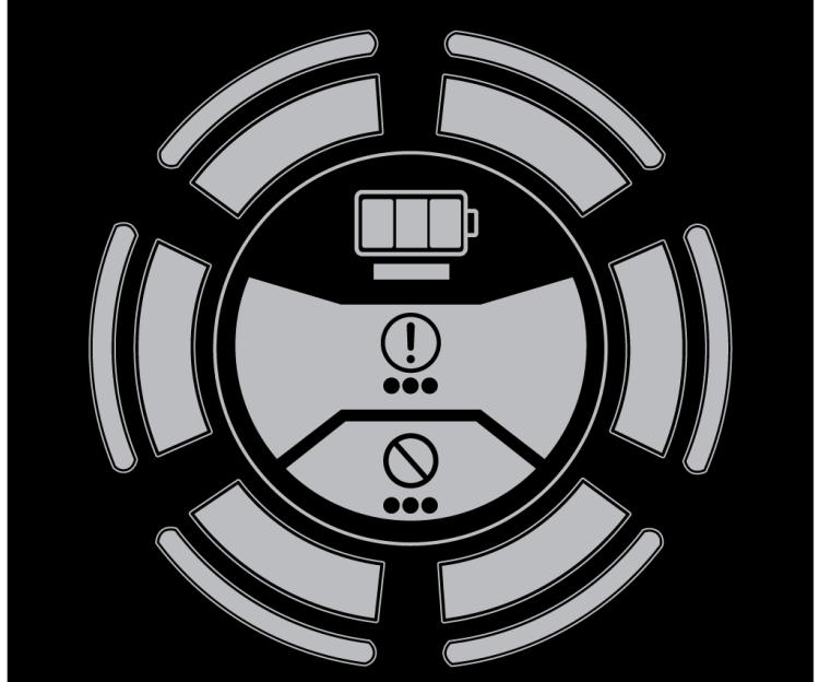
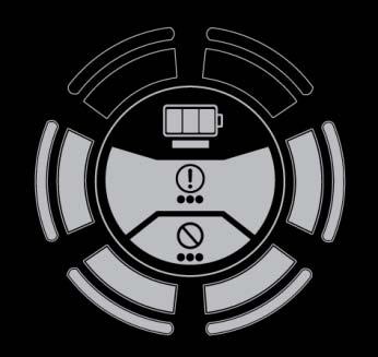
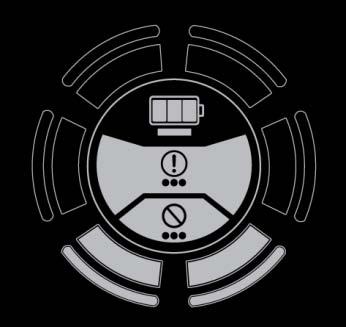
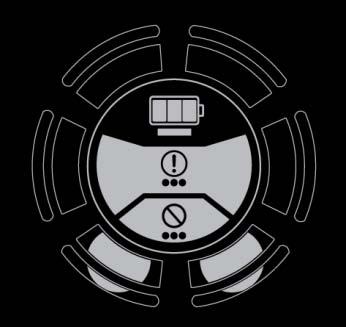
Figure 7. LED display
The LED display shows the following information:
• Level of battery charge, the different level indications are explained in Table 2 below.
• Fault indications: Green = System OK Flashing yellow = Warning Flashing red = Error
© Mitsubishi Forklift Trucks 2013. All rights reserved. Revision: C Document ID: 615026 21 (214)
Table 2. Level of battery charge indications
LED DISPLAY DESCRIPTION
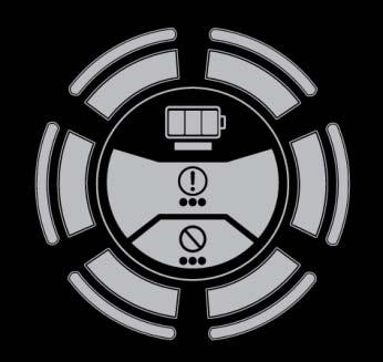
Green light in all six dial segments = Battery charge level at 70 - 100%
Yellow light in the bottom four dial segments = Battery charge level at 40 - 70%
Red light in the bottom two dial segments = Battery charge level at 20 - 40%
Slowly flashing red light in the bottom two dial segments = Battery charge level at 0 - 20% (battery is empty, recharge immediately)
In case of a warning or error, press and hold down the brake release button to read the warning or error code. The LED display uses a flashing light sequence to indicate the error code as explained in Table 3.
© Mitsubishi Forklift Trucks 2013. All rights reserved. Revision: C Document ID: 615026 22 (214)
Table 3. Fault indication sequence
FUNCTION DESCRIPTION
GREEN LED A flashing green LED indicates the first digit of the code.
BREAK A break of 500 ms.
YELLOW LED A flashing yellow LED indicates the second digit of the code.
BREAK A break of 500 ms.
RED LED A flashing red LED indicates the third digit of the code.
BREAK A break of 1000 ms, after which the sequence is shown again.
EXAMPLE FOR ERROR CODE 147
Green LED flashes once.
Yellow LED flashes 4 times.
Red LED flashes 7 times.
Multi-function display
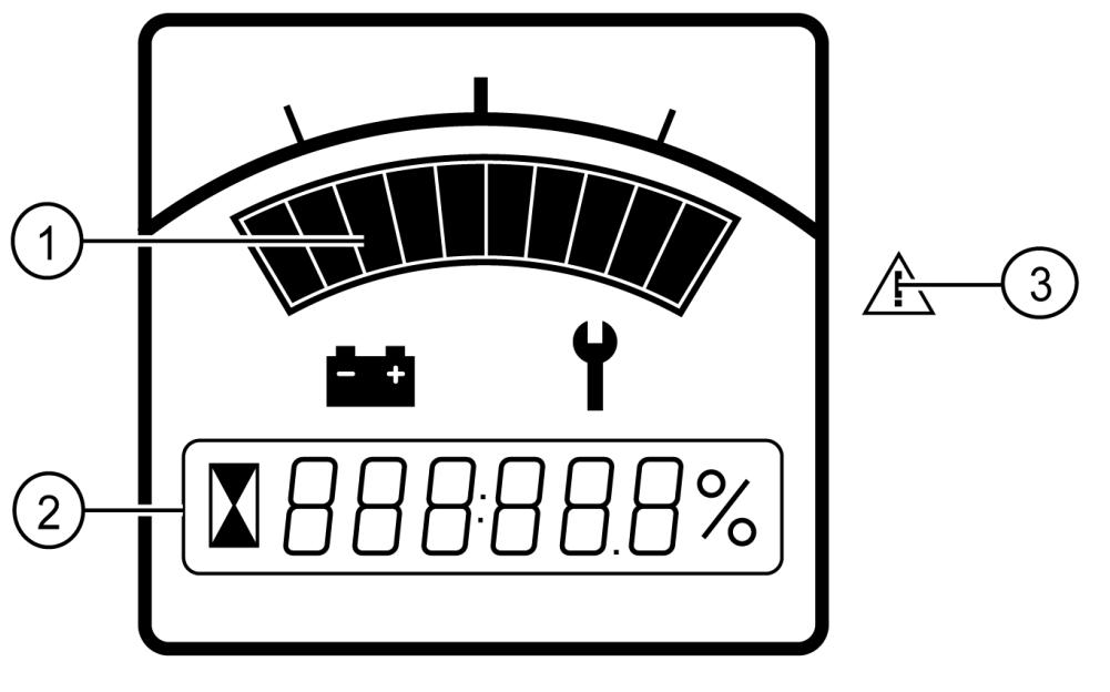
Figure 8. Multi-function display
1. Level of battery charge 2. Indication of operational hours, system messages and fault codes 3. LED indicator
© Mitsubishi Forklift Trucks 2013. All rights reserved. Revision: C Document ID: 615026 23 (214)