11 minute read
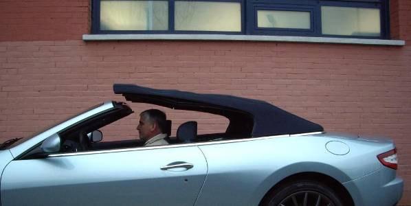
Maserati GranCabrio


Inhibition of the roof movement
The following situations will inhibit the automatic opening and closing of the roof:
• The vehicle is driving faster than 30 Km/h
• The trunk lid is open or not correctly closed
• Failure of the side windows operation
• Overheating of the roof control mechanism
• Too low battery voltage
• Too low external temperature (below -10°C)
• The vehicle is not able to detect the driving speed
• Failure in the roof control system
In such a case a red roof failure icon will be displayed alongside a message
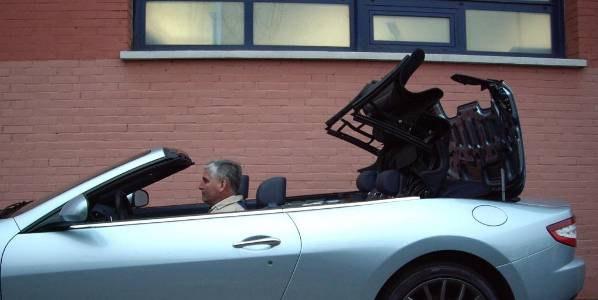
Roof closing cycle step by step
When the NCP receives a roof closing request from the driver, it will only proceed if all conditions for roof movement are met. The NCP subsequently sends a command signal to the NPG and the NPP to lower both front windows (if closed).
When the front windows are completely open, the NCP will lower both rear side windows (if closed).


Both tonneau cover cylinders extend to unlatch and open the tonneau cover.
Both main cylinders retract to lift the roof out of its stowage space.
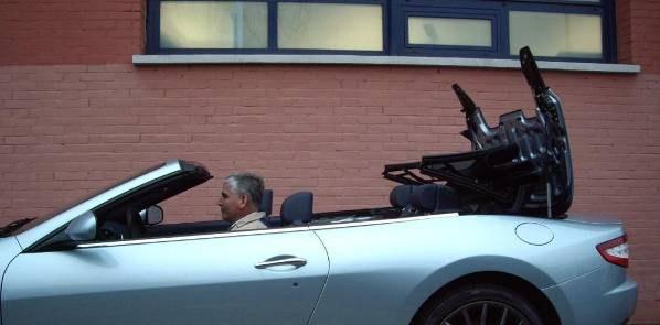
While the roof unfolds, the bowden cables attached to the roof structure that kept the Cpillar flaps stretched will release The C-pillar flaps fold down by the force of their spring.
The main cylinders are completely retracted and the C-pillar flaps folded down.
The tonneau cover cylinders retract to close and latch the tonneau cover

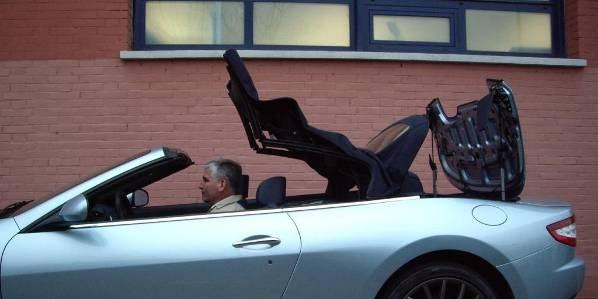
The tension bow cylinders extend This stretches the front part of the roof and lowers the rear part of the roof.
The tension bow cylinders are fully extended Now the electrical front latch mechanism takes over to lower the front part of the roof towards the windscreen frame. This movement tensions the complete roof The front part of the roof latches to the windscreen frame

A beep confirms that the roof is completely closed. If the driver continues to hold the button also the side windows will close The NCP first closes the rear side windows.

The NCP sends a signal to the NPG and the NPP to close both front windows.


The cycle is now complete and the user can release the switch. The complete roof remains tensioned, also after the hydraulic pressure releases
For the roof opening cycle, the different steps take place in the opposite order.
Description of the roof system
The roof system contains the following main components:
• A hydraulic high pressure pump driven by a DC-motor provides the hydraulic pressure to the system
• A number of solenoid valves to control the functionality of the hydraulic cylinders
• 4 hydraulic cylinders to operate the roof mechanism
• 2 hydraulic cylinders to operate the tonneau cover
• A front latch mechanism driven by a DC-motor to lock the roof to the wind screen frame and tension the complete roof
• A number of Hall sensors and micro-switches to monitor the roof and tonneau cover position.
• A central ECU (NCP) which controls the complete system

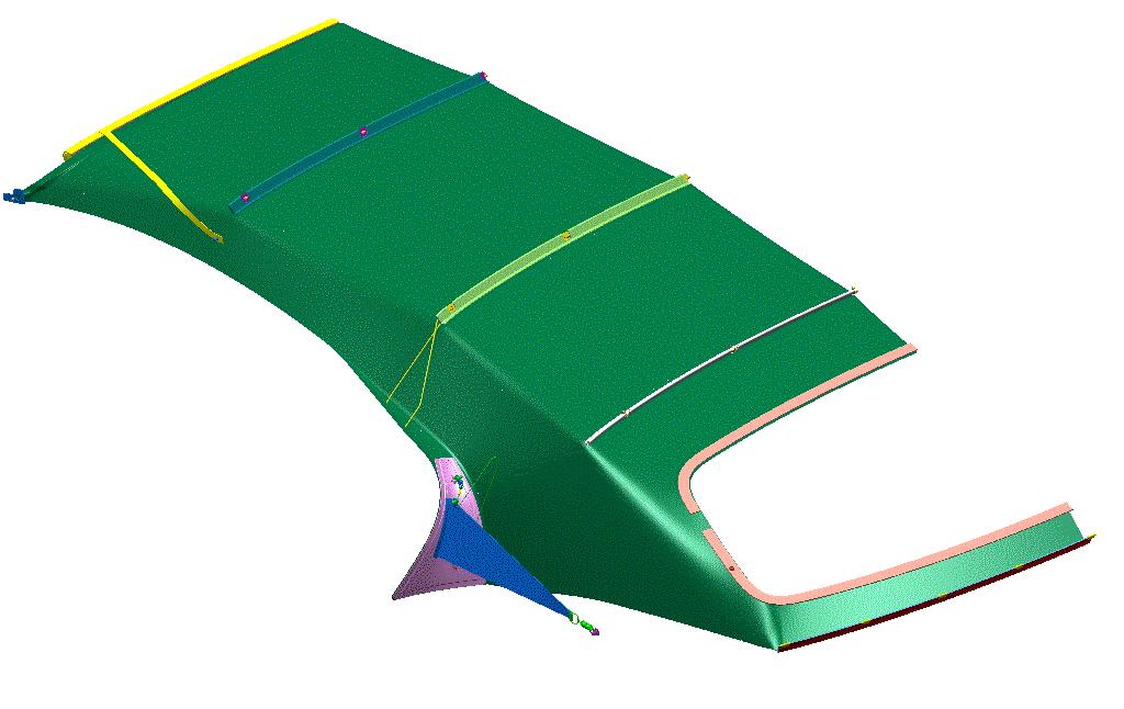
Soft roof components


The different “soft” components of the roof can be replaced individually in the event of damage. For the removal of these parts it is advised to remove the soft top from the vehicle and carry out the operations on a bench Also the various seal elements and contour bows are available as service parts
Caution
Maximum precaution must be displayed when working on the soft top in order to avoid the visible components from getting dirty. Stains from oil or grease are very difficult to remove, especially from the inner lining. Always use new or degreased tools when working on the inner lining.
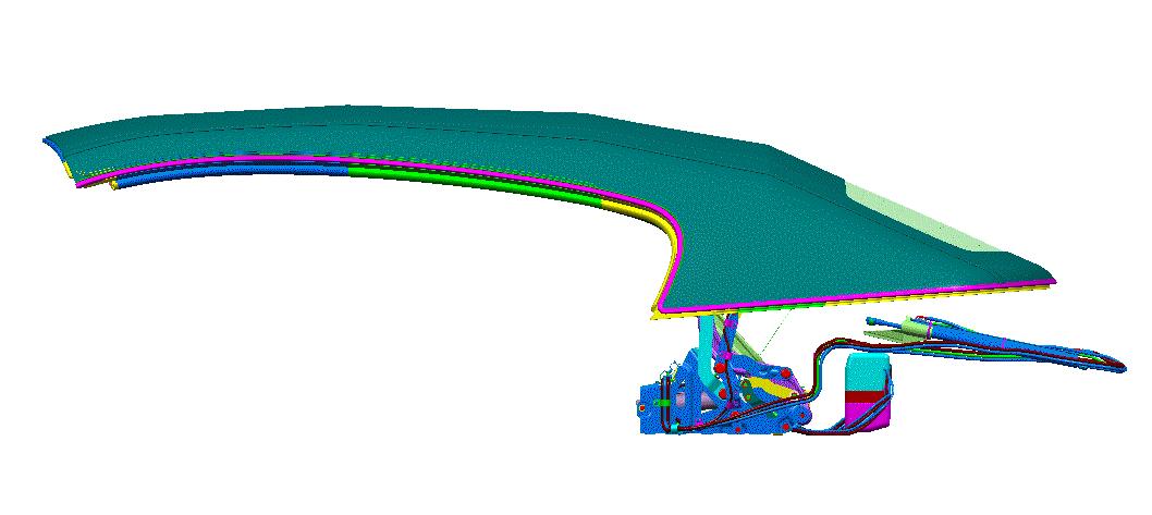
Roof movement mechanism
1. Roof structure
2. Scissor mechanism
3. Roof support frame
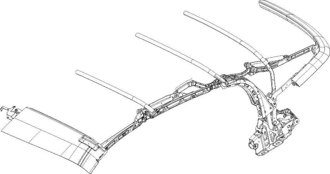
4. Main cylinder
5. Tension bow cylinder
The combined aluminium and steel roof structure (1) is operated by a cast steel scissor mechanism (2) The complete structure is connected to two roof support frames (left and right) which house also both main cylinders (4). The retracting of both main cylinders, which are extended when the roof is folded away, will lift the roof out of its storage area and start the unfolding. The tension bow cylinders (5) operate the scissor mechanism. This will further extend the roof towards the windscreen frame until the front latch mechanism takes over. At the same time, the tension bow cylinders lower the rear part of the roof (after the tonneau cover has been closed) The retracting of the tension bow cylinders generates the opposite movement.
Each roof support frame is bolted onto the vehicle body, inside the roof storage area. Spacer plates between the roof support frames and the vehicle chassis are used to align the roof with the vehicle body.

Note: the kinematic roof structure does not require any adjustments
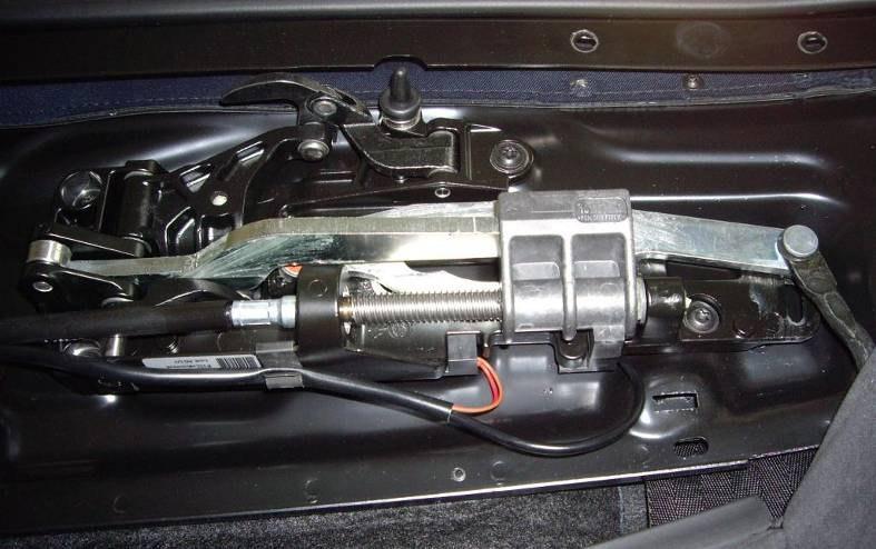
The front latch mechanism, located in the front header of the roof, is electrically driven and has the purpose of approaching and locking the soft top to the windscreen frame. It completes also the tensioning of the roof structure. It is composed of the following components:
Component description:
• DC-motor assembly: The 12V DC-motor is driven by the NCP and can rotate in two directions: left for the latching of the roof and right for unlatching This is managed by the NCP by inverting the polarity of the power supply The DC-motor drives two flexible shafts which are connected to the actual latch mechanisms at both sides
• Flexible shaft: two bowden cable-type flexible shafts transfer the motor movement to both latch mechanisms. Note: the shafts are marked “left” and “right”, they can not be swapped.
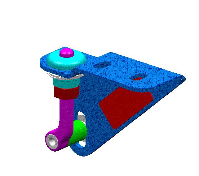
Latch mechanism

Centering pin latch
Tensioning rod
3. Latch mechanism (left): The latch mechanism uses the rotational movement from the flexible shaft to drive a spindle mechanism which closes the latch and pulls the tensioning rod. A centering pin will guide the roof into the windscreen frame. If the shaft rotates in the other direction, the latch will open and the rod will push. Two added Hall sensors will detect when the DC-motor reaches its end position in both directions


4 Latch mechanism (right): identical to the one at the left side, but without the two Hall sensors.
5. Tensioning rod (left + right): the last step in the roof closing movement (approaching the roof front to the windscreen frame) is completed electrically by a tensioning rod at both sides of the roof mechanism. By this way the roof remains tensioned also when the hydraulic pressure drops after closing. The opposite movement is done when the DC-motor inverts its rotational sense
6. Latch receiver (left): this is integrated in the windscreen frame, left hand side.
7. Latch receiver (right): the latch receiver placed at the right hand side is identical to the one at the left hand side, but an added Hall sensor will detect if the latch is locked.


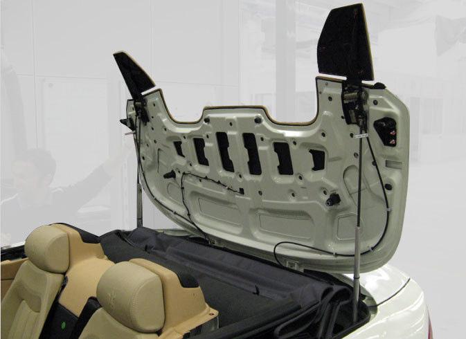
The tonneau cover has the purpose of removing the folded soft top from the eye when the roof is open. By this way the pure and clean body shape of the vehicle is maintained also when driven open.
Other than a pure aesthetic function, the tonneau cover protects the roof and roof mechanism from dirt and dust and reduces aerodynamic drag When the roof is closed, the tonneau cover acts as a platform on which the rear part of the roof will rest
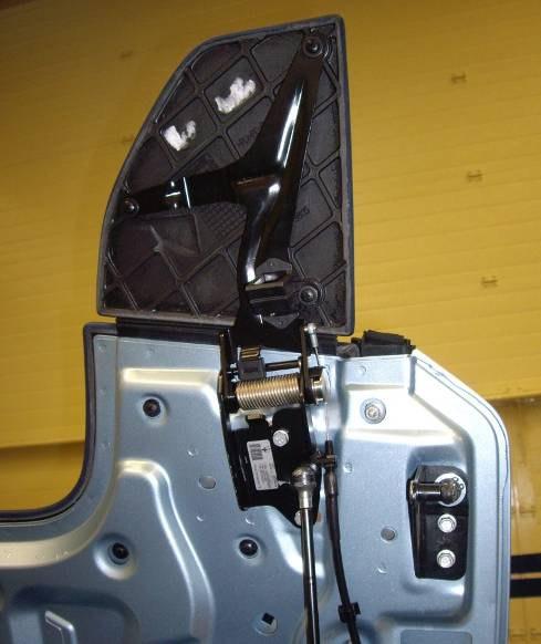
1. Latch
2. Bowden cable
3. attaching point for tonneau cover cylinder
4. Lever
5 Manual release cable
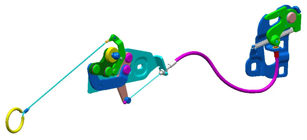
6 Tonneau cover closed micro-switch
7. Tonneau cover open micro-switch
The tonneau cover is latched and unlatched hydraulically by the movement of the tonneau cover cylinders To this end a latch mechanism is fitted at both sides of the soft top storage area.
At the end of the tonneau cover closing movement, the retracting of the tonneau cover cylinder operates a lever mechanism which pulls the bowden cable and closes the latch in an overcentering movement. The opposite movement happens by the extending of the cylinder before the tonneau cover starts opening.
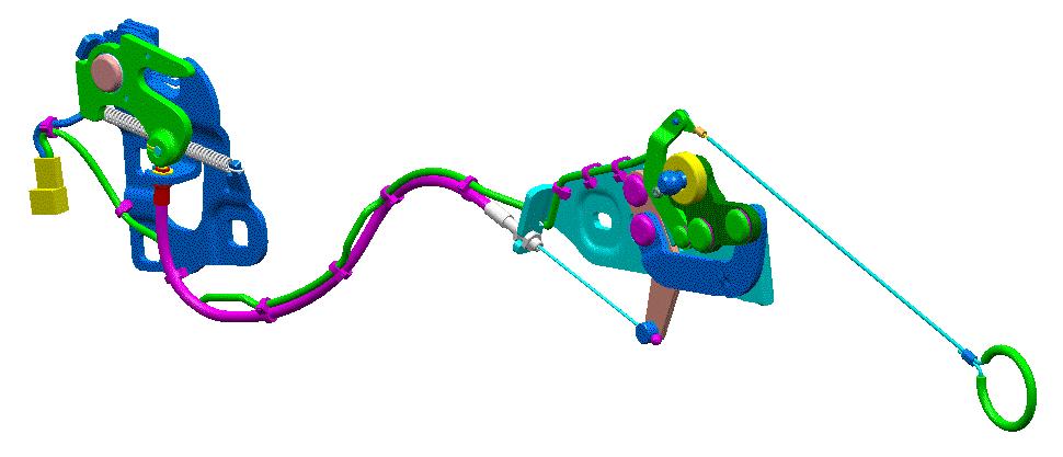
Two micro-switches (right hand side only) will inform the NCP about the open /closed status of the tonneau cover
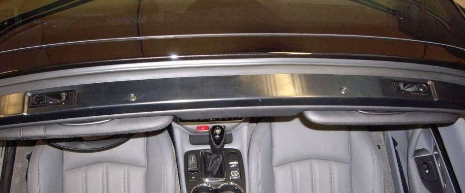
In case there is the need to manually open the tonneau cover, a manual release cable is attached to both latch mechanisms and can be accessed by removing two small panels from the boot side mouldings
A striker with adjustable striker pin is fitted to both sides of the tonneau cover The pin must be adjusted in such a way that the tonneau cover is perfectly aligned with the vehicle body when closed


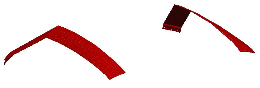
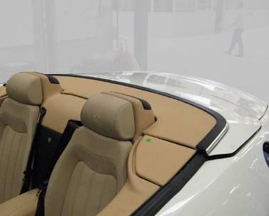
C-pillar flaps
Both C-pillar flaps are operated by the movement of the roof main cylinders A bowden cable, connected to the roof main mechanism, will pull the flaps straight when the roof is folded away inside its storage space

The cables will release and the flaps will hinge down by the force of a spring as soon as the roof is lifted out of the storage space
The flap hinge mechanism can be adjusted to make sure the flaps are perfectly in-line with the tonneau cover when the cables are tensioned
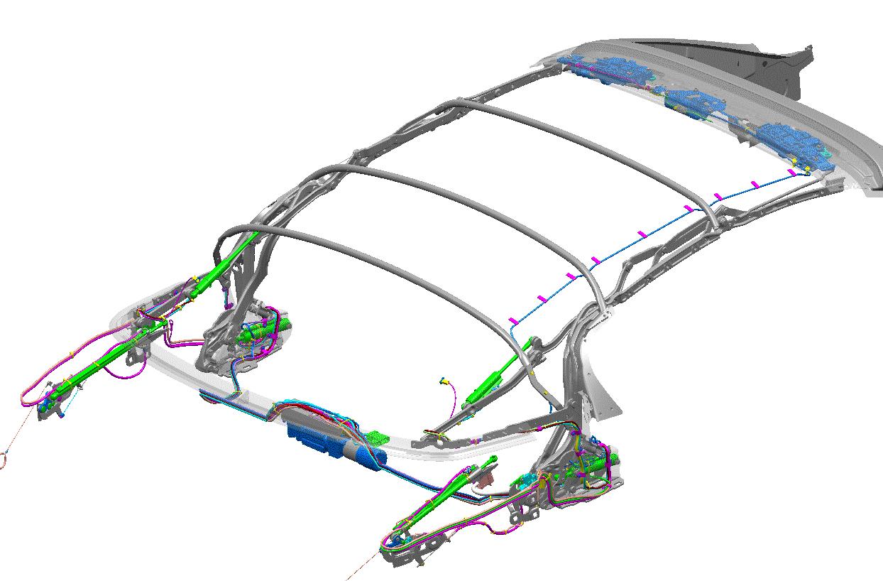
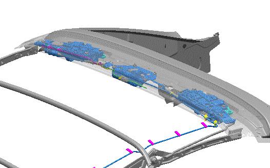
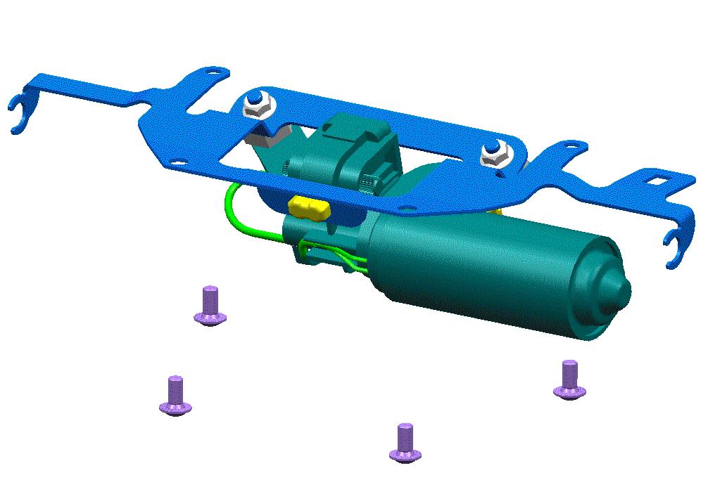
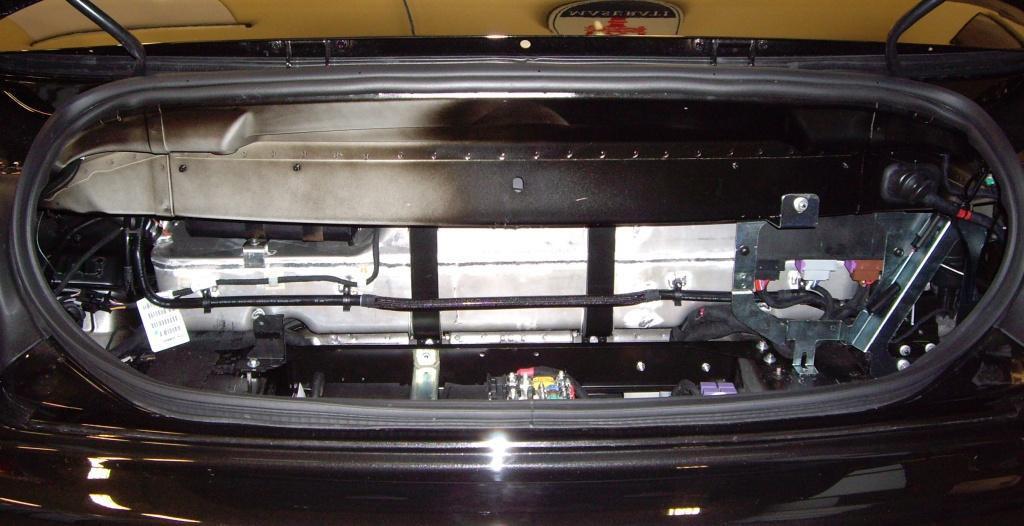
Hydraulic components
1. Hydraulic unit foam cover
2 Hydraulic unit
3. Hydraulic cylinder (tension bow), left
4. Hydraulic cylinder (tension bow), right
5 Hydraulic cylinder (main), right
6. Hydraulic cylinder (main), left
7 Hydraulic cylinder (tonneau cover), left
8. Hydraulic cylinder (tonneau cover), right
9. High pressure pipes, right
10 High pressure pipes, left
The Hydraulic (2) unit is made of a high pressure pump, a machined aluminium valve block, three solenoid valves and a reservoir
The high pressure pump (190 bar) is driven by a DC-motor and can rotate in two directions, one for the roof opening operation and one for the roof closing operation
The reservoir contains the hydraulic fluid for the system and has Min and Max level marks on it. Oil can be topped up by a filling tap. See the part “Service operations on the roof system” for oil level check and topping up indications.
The three solenoid valves are commanded by the NCP and control the functionality of the tension bow and the tonneau cover cylinders Further, the hydraulic unit contains an NTC temperature sensor to monitor the pump operating temperature
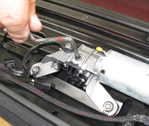
The hydraulic unit can only be replaced as a complete unit. It can be accessed by opening the tonneau cover and lifting out the roof. The hydraulic unit is wrapped in a foam cover (1) to isolate noise and vibrations.
The six hydraulic cylinders (3 to 8) can each be replaced separately in case of damage
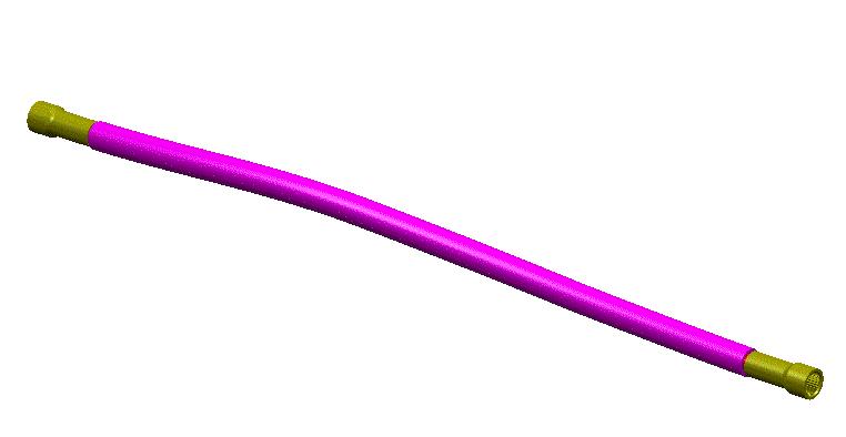
A total of 12 flexible high pressure pipes (9,10) are used, which can also be replaced separately in case of damage They are fixed to the hydraulic unit and to the different cylinders by quick-release connections.

The hydraulic unit can be clearly viewed after removing its


The hydraulic pump is activated only when a movement of the roof is requested. It can rotate in two directions The rotational sense of the pump is inverted by inverting the polarity of the DC-motor, which is regulated by the NCP A pressure control valve will regulate the hydraulic pressure at 190 bar in both directions
When the pump rotates to the left, the blue circuit will be pressurised and the main cylinders will retract. The roof will close (= unfold).
When the pump rotates to the right, the red circuit will be pressurised and the main cylinders will extend. The roof will open (= fold away).
The purple circuit is always pressurised when the pump rotates

Three solenoid valves (SV1, SV2 and SV3) are commanded by the NCP and will regulate the movement of the tonneau cover and the tension bow cylinders
When SV1 is activated, the tonneau cover cylinders will extend and the tonneau cover will open. When SV1 is deactivated, the tonneau cover cylinders will retract and the tonneau cover will close.
When SV2 is activated, the tension bow cylinders will extend and the roof will be tensioned When SV3 is activated, the tension bow cylinders will retract and the roof will release tension
Maserati GranCabrio
Roof control node (NCP)

Body
The roof control node or NCP (Nodo Capote) performs the following main functions:
• Control the convertible roof mechanism
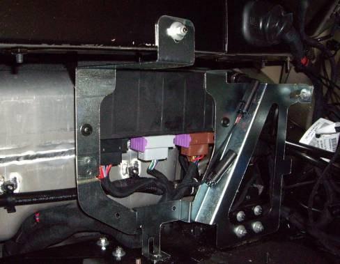
• Operate the rear lateral windows
The NCP is connected to the B-CAN line for data exchange with other vehicle nodes and for diagnostics
Connector A (black): Vehicle
Connector B (grey): Roof
Connector C (brown): Hydraulics
The operating voltage of the NCP is 8-16V
The NCP is protected against voltages < 8V, voltages > 16V, and against reversed polarity.
Roof control node (NCP)
Roof fuses
The NCP is power supplied on different pins and through 4 different fuses, each secure a specific part of the roof system:
• a 40A fuse (F109) for the ECU operation, the front latch and the solenoid valves.
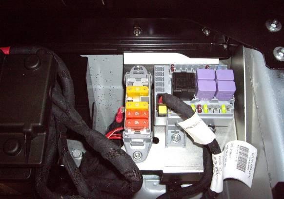
• a 40A fuse (F108) for the hydraulic pump
• two 20A fuses (F61 & F65) for both rear window lifters.
Misuse protection
There are several protections against misuse implemented. The operating time of the hydraulic pump is monitored. To prevent overheat of the hydraulic pump motor and the printed circuit board (PCB) of the NCP, three temperature stages are implemented
The user gets a warning on the instrument cluster, opening /closing allowed
Only closing allowed Alert
An NTC resistor is built into the hydraulic pump motor so the software can monitor what temperature the pump motor operates at A thermal counter is implemented in the software, after a defined time of operation the pump motor and the PCB have to cool down for a defined time before the next operation can start. The NCP can only go to Roof Sleep mode when the thermal counter has reached zero.
Vehicle speed monitoring
To protect the roof system, the vehicle speed will be monitored by the NCP during roof opening, during roof closing, in stop-mode and in manual mode Depending on the velocity, the driver will be informed by several acoustical and optical warnings
• To start a new hood operation, the velocity must be below 30 km/h If the velocity exceeds 30 km/h, the hood operation will be stopped. The operator has to reduce the vehicle speed below 30 km/h and reactivate the roof operation demand to continue the hood operation.
• In case of exceeding the 50 km/h, a DTC will be stored into the error memory Additional to the DTC the relevant sensor information is stored
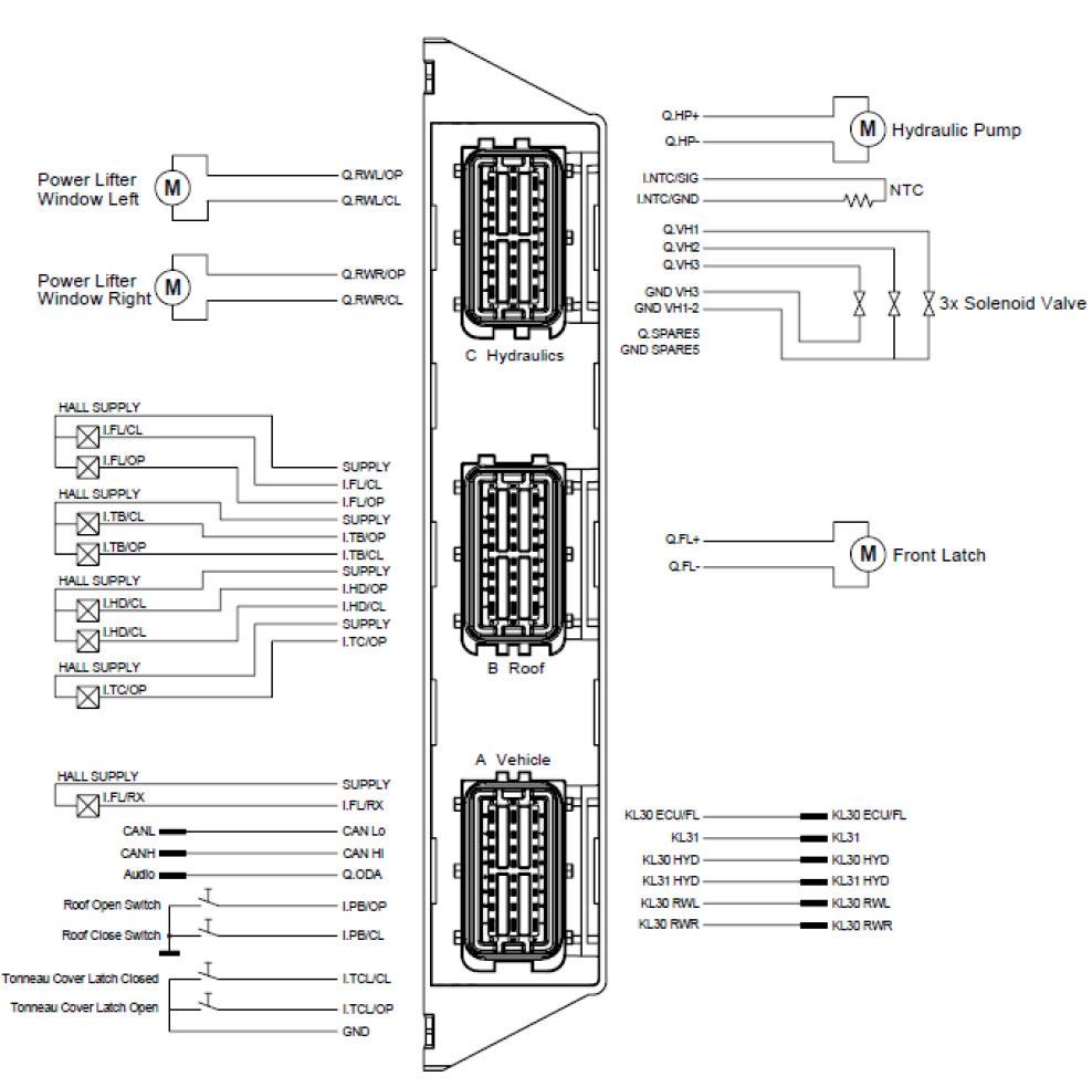
Functional diagram:
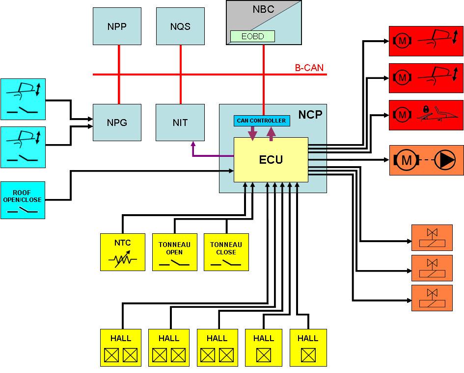
Driver commands:
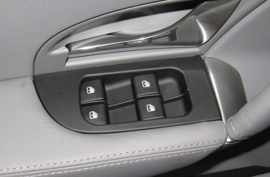
Push buttons on the drivers door to operate the left and right rear window lifters. These interrupters form an integral part of the driver’s door node (NPG). The window open /close commands are sent by the NPG to the NCP via the B-CAN line.
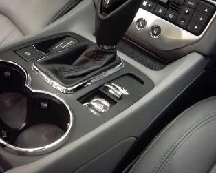
A push button to operate the soft top is located on the central console Two contacts provide each an active low signal to the soft top node (NCP) When the user releases the button during operation, the roof will stop moving
Inputs / sensors
An NTC resistor is integrated in the hydraulic pump unit to measure in which temperature area the pump motor is working. This is used to protect the motor from damage due to overheating.
A double micro-switch is used to measure the position of the tonneau cover The tonneau cover latch open is activated when the tonneau cover enters the striker during closing; the tonneau cover latch closed is activated when the tonneau cover has reached its end position during closing
The NCP receives a total of 8 Hall inputs to measure the position of various components:
• The Front Latch Open and Closed sensors are used to detect if the front latch motor starts moving, and reaches the end position The sensors are positioned on the spindle mechanism of the left hand side front latch
• The Front Latch Received sensor is used to detect if the front latch is closed. If the sensor is active, the roof is completely closed. This sensor is integrated in the right hand side latch receiver, located on the windscreen frame.
• The Tonneau Cover Open sensor is mounted onto the right hand side tonneau cover cylinder to detect if the cylinder is at the end position Then the tonneau cover is completely open
• The Tension Bow sensors (Open and Closed) are used to detect the position of the tension bow. This information is used to determine the next step in the roof opening and roof closing cycle. They are fitted on the right hand side tension bow cylinder.
• The Roof Open and Closed sensors are used to detect if the main cylinder is at the end position. They are fitted on the right hand side main cylinder.