13 minute read
Fuel System


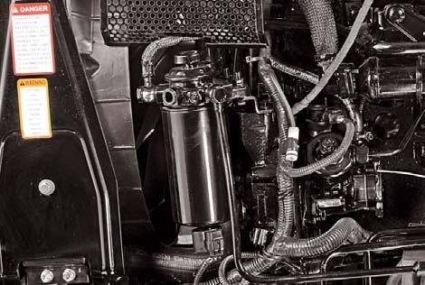
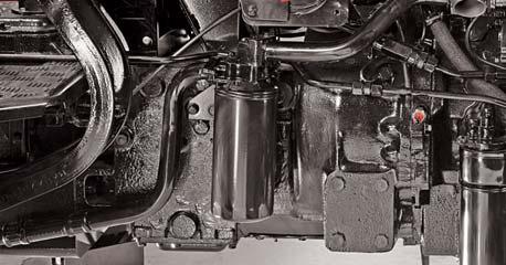
Fuel Filter
This filter provides clean, moisture free fuel for the injection process. A hand primer is provided to manually remove excess air from the fuel filter and fuel lines.
Major Components:
•Hand Primer
•Air Bleeding Screw
•Fuel Filter
Fuel enters the filter at inlet (A) and flows through the filter element separating water if contents before flowing through outlets (B) to the fuel injection pump.
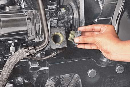
Since water and contaminants settle at the bottom of the sediment bowl, a drain plug (i.e. Adaptor cum Water Sensor) is provided.
Drain water from the fuel filter when water level indicator in instrument cluster glows on.
To drain water from fuel filter, unscrew the water sensor in anticlockwise direction by hand. Rotate only 1 to 2 turns by hand. Place a small tray to collect water or water and diesel emulsion. Tighten water sensor by rotating clockwise. Tightening torque 2 to 3 Nm or hand tighten and fix connector (C).
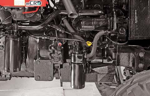
Servicing the Fuel Filter
1.It is recommended to replace the fuel filter every 250 hrs.
2.To remove Filter, unscrew the filter (D) from adaptor (E).
3.Check O'rings of fuel filter for any crack / damage. Smear oil on the new O'ring before installation.
4.Assemble the new filter. Do not over tighten.
5.Clean Water Sensor to remove sludge and retighten to filter.
6.Prime the system and bleed the filter. Tighten the bleeding screw.
NOTE : Drain water once in a week or whenever the water level indicator on dashboard glows "ON" continuously, if water contamination is excessive. Continued driving with water accumulation in fuel filter will cause damage to the fuel pump / other fuel system components.
NOTE : Replace fuel filter at the recommended period or whenever it gets clogged. Discard the old filter and do not repair or clean the filter. Always fit the spin-on filter dry.
Oil Level Check :
Check engine oil before starting the engine.
1.Remove dipstick gauge (A) provided on the right hand side of the crankcase.
2.Oil level should be between the two marks provided on the dipstick (A).
Never allow to let the oil level drop below the ‘Lower’ mark. Add only recommended grade of oil (15W40).
Engine Oil Filter
The life of engine and turbocharger depends upon clean oil being circulated to its bearings. In the normal course of engine operation the lubricating oil undergoes changes which produce harmful by-products. The purpose of the oil filter is to separate and remove dirt and other injurious foreign materials from the oil and prevent these from being circulated in the engine.
The oil filter should be replaced as per Routine Service Schedule given in this Manual or whenever engine oil is changed.
Changing Spin On Filter
1.Ensure that engine is stopped before changing filter.
2.Unscrew the oil filter (B).
3.Prime the new spin-on filter with clean oil.
4.Screw the new filter to the adapter.
5.Move the Hand and foot throttle to engine "Idle" position.
6.Start the engine, check the oil pressure gauge to see whether the lubricating oil is circulating through the Engine.
7.Inspect the oil filter for oil leaks.
Oil Change
Change Engine Oil as per Routine Service Schedule given in this Manual.
1.Ensure that the engine is stopped before changing oil.
2.Remove the drain plug (C) provided at bottom of oil sump.
3.Allow the oil to drain at least for five minutes. All the oil can be drained out when engine is still warm.
4.Now reinstall the drain plug (C). Service the oil filter as explained below.
5.Remove the oil filler cap (D) to expose the oil filler neck.
6.Refill the oil sump slowly by recommended grade of oil (15W40) from the oil filler neck.
7.Clean and place the oil filler cap (D) again. Stop the engine immediately if Oil pressure is not recorded within 10 seconds of engine starting or Leakage is observed. Get the cause identified and rectified before proceeding further.
Turbocharger
Check the turbocharger periodically as follows.
1.Move the Hand and foot throttle to engine “Idle” position.
2.Inspect the oil filter for oil leaks through oil supply and drain line.

3.Stop the engine immediately if leakage or abnormal sound is observed. Get the cause identified and rectified before proceeding further.
Do not drain the oil when the engine is hot. Wait for the engine to cool.
NOTE: Engine oil and filter element must be changed after initial 50 hrs. of operation in new tractor or whenever major overhaul of engine is carried out and subsequently after every 500 hrs. (bigger element) or 1 year, whichever is earlier.
To avoid delays, we recommend that you carry extra filter elements on hand so that replacements can be made at the correct time. The FILTER is located on the right-hand side of the crankcase.
Filling oil consumes time. Allow sufficient time for the oil to settle down in crankcase. Dispose the used oil properly.
Battery Maintenance Cleaning
Battery terminals must be kept clean and tight. The cable terminals will corrode and interfere with battery performance unless regularly checked. A light smear of petroleum jelly on the terminal posts and connections will help to resist corrosion. Occasionally remove the connections and clean the terminal posts with wire wool or emery cloth, smear with petroleum jelly and reassemble. Wash the battery top with warm water and soda. Ensure that none of this solution gets into the battery cells. Finally rinse with plain water. The vent holes in the filler caps should be open at all times.
Servicing
If the battery shows need of charging it must be given immediate attention. Keeping the battery fully charged not only preserve its life but makes itself available for instant use when needed.
When replacing the battery the earth cable must be connected to the negative (-) terminal and the battery cover secured in its correct position.
Do not, under any circumstances, allow an electric spark or open flame near the battery, during or immediately after charging. Do not lay steel tools across the terminals, as this may result in a spark or a short circuit which could cause an explosion. Be careful to avoid spilling electrolyte on hands or clothing.
Effect of Low Temperatures
Battery capacity is greatly reduced in cold condition which has a decided numbing effect on the electrochemical action of the battery. Taking 100% of cranking power at 800F then at 320F, only 65% and 00F only 40% cranking power is available.
If your tractor is not to be operated for some time during winter months, it is advisable to remove the battery and store in a dry place where the temperature will not fall below freezing point. Maintaining the electrical system in good working order will enable the alternator to provide the current needed necessary to keep battery fully charged thus ensuring maximum efficiency of the electrical devices.
Ensure that the terminals are clamped tight, and the battery is securely fastened down in the battery tray.
Do not over-tighten.
When the alternator is charging, an explosive gas is produced inside the battery. Do not use an exposed flame and do not smoke while checking the battery.
Before working on any part of the electrical system disconnect the battery ground cable. Do not reconnect this cable until all electrical work has been completed. This will prevent short circuits and damage to electrical units.
Electric storage batteries give off a highly inflammable gas when charging and continue to do so some time after receiving a steady charge
NOTE : Contact 'Exide' Dealer for Warranty.
Website : www.exideworld.com
Phone : 1 - 800 - start it
Alternator
Following checks of alternator charging system will avoid many problems that might otherwise develop.
1.Check belt tension. Refer your operator's manual for proper belt tension.
2.Keep pulley nut tight.
3.Check alternator terminals and cable connections for good condition, secure fastening and freedom from corrosion.
4.Check battery cables and connections for good condition, secure fastening and freedom from corrosion.
5.If battery will not take adequate charge, or is otherwise unsatisfactory replace battery.
Charging Circuit
Should the battery be in a low state of charge, which will be shown by lack of power when starting or poor lights. This may be due to either alternator not charging or giving lower intermittent output, then proceed as below : Check Battery Charging Indicator when the engine is running steadily at working speed.
If the Battery Charging Indicator glows, have the equipment checked by your Mahindra tractor Dealer. Inspect alternator drive belt and adjust as necessary. Examine the charging and field circuit wiring, tighten any loose connections, replace any broken cables, pay particular attention to the connections.
NOTE : Alternator maintenance should be done by Authorised Dealer.
Too tight a belt will cause rapid wear of belt and damage to bearings.
A slack belt will not drive the alternator and therefore the battery will not be charged.
Starter Motor Removal
1.Disconnect the earth cable from the battery, battery to starter solenoid coil cable, key switch to solenoid coil cable.
2.Remove the mounting bolts and withdraw the starter motor. To install the starter motor, reverse the above procedure.
To avoid damage to alternator charging system, service precautions should be observed as follows.
1.Never make or break any of the charging circuit connections, including the battery when engine is running.
2.Never short any of the charging components to ground.
3.Do not use a jumper battery of higher than 12 volts.
Always disconnect the battery ground cable before carrying out arc welding on the tractor or any implement attached to the tractor. Use only specified cable for replacement
Should the starter motor be removed, and a replacement motor or drive end bracket be fitted, a check must be made of the out of mesh clearance after assembling the starter motor to the engine. The dimension between the leading edge of the pinion and the engine flywheel should be no less than 0.32 cms.
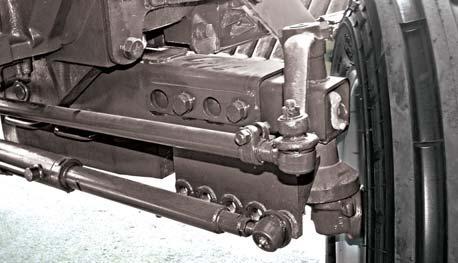
Front Axle - Front Wheel "Toe-in" Check
In the event of the tie rod setting being interfered with, then it is necessary to adjust the TOE-IN. Before measuring and adjusting the TOE-IN, ensure the front wheels are in the straight ahead position and the front axle is not tilted. After adjusting the front wheel tread and with all connections secured, the front wheels should have 0 to 3 mm TOE-IN.
Measure the distance between the outer edges of the wheel rims at the same height as the hub caps. Mark the point measured and turn the wheels one half revolution so that the marked points are at the rear. Measure again the distance between these two points and this distance must be the same as measured before without variance. To adjust the TOE-IN shorten or extend the tie rod by removing the left hand side tie rod bolt and screwing the rod clockwise or anti-clockwise.
Front Wheel Check
After the first 50 hours operation check the front wheel axle nuts for tightness. If these nuts are loose, re-tighten.
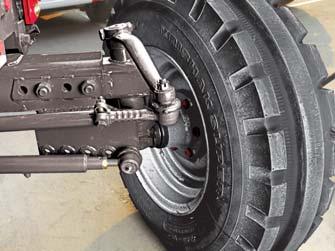
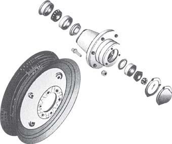
Greasing the Front Wheels
After every 400 Hrs. of operation replace the grease in front wheel hubs as explained below.
1.Jack the front wheels clear of the ground.
2.Remove the hub cap (A), remove split pin, castle nut (B) and washer.
3.Remove the bearing (C), (keep this bearing clean) and then remove the wheel.
4.Clean inside the hub (D). Remove the old grease from the bearings and retainers, clean with solvent and repack with Molybdenum Disulfide chassis lubricant.
5.Now reassemble in the reverse sequence.


Preloading Bearings
When replacing the front wheels it is essential that bearings are pre-loaded properly. To ensure this the nut 'B' should be tightened up while the wheel is being revolved until it stops. Slacken off the nut upto the first pin hole where the washer is free to move and place the split pin. It is advisable to leave the bearing (E) in place and clean with a brush and solvent. Before reassembling the bearings, repack the rollers with new grease.
When the TOE-IN adjustments have been made the tractor should be jacked-up and the axle tilted to its maximum tilt position. In this position the wheels should be turned to the full left-hand lock and at this angle the welded stop on the steering knuckle pivot pin sleeve should be hard against the stop on the steering knuckle.
The oil and reservoir is common for Transmission, Hydraulics and Steering.

Transmission Oil Level
Remove the dipstick cum breather (A) and check oil level. Refill oil from filler neck (B) till the required level.
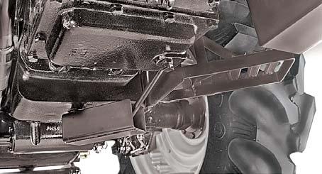
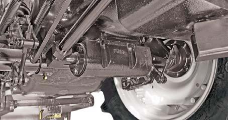
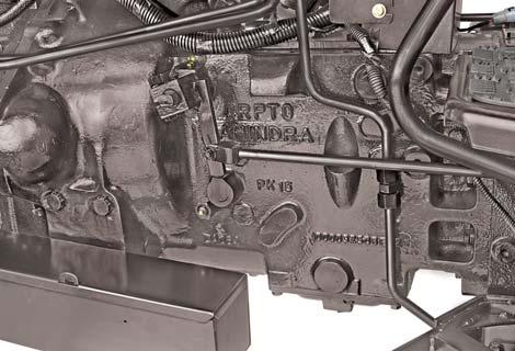
Transmission Oil Drain
A drain plug (C) is provided on the transmission for draining transmission oil.
Hydraulic Suction Filter
The oil filter element (D) should be replaced initially at 50 hours and subsequently after every 500 hours of operation or whenever hydraulic oil is changed.

Transmission Strainer
Transmission strainer (E) should be removed and cleaned initially at 50 hours and subsequently every 1000 hours of operation or whenever the transmission oil is changed.
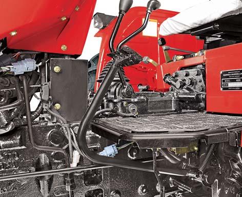
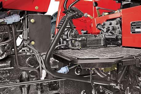
Clutch Pedal Adjustment
The clutch pedal should be adjusted to give a measurement (A) of 6.7” (17 cm) between the pedal pad and the foot plate.
Clutch Pedal Free Play
With the clutch fully engaged, the pedal should have a free movement (B) of 1/2" (1.25 cms).
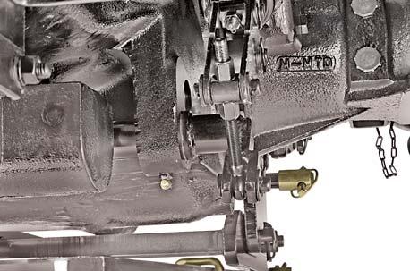
The free movement is obtained as follows :

1.Loosen the retaining bolts (C)
2.Move the pedal round the clutch release shaft (D) until the required adjustment has been made.
3.Retighten the retaining bolts after adjustment.
Disc Brakes
The brakes consist of two actuating discs, two friction discs and operating linkages, enclosed in a brake housing. The two friction discs are driven by bull pinion/brake shaft, the speed of rotation of which is reduced by the engagement of the actuating discs when downward pressure is applied to the brake pedals. The actuating discs force the friction discs against the inner face of the brake housing and the outer surface of bull pinion cage.
Brake Pedal Adjustment
Adjust the brake as follows :
1.Loosen the jamnut (A) on the foot-brake adjuster bolt.
2.Tighten the nut (B) to tighten the brake and loosen the nut (B) to loosen the brake.

It is very important to ensure that both brakes have the same amount of free movement before taking hold. A definite way to check this equalisation is to jack up the rear wheels so that they turn freely. Start the engine and operate in 3rd or 4th gear. Application of the brakes should slow both wheels at the same time, and also tend to reduce engine speed. If, when the brakes are applied, one wheel stops and the other continues to spin, adjust the brakes until both wheels stop simultaneously with application of the brakes.
Brake Pedal Free Play
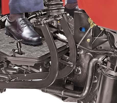
Measure free play of pedal stroke (C). Ensure free play is within specified limits. If free play is not within specified limits, adjust linkage as shown below. Free Play - Distance 3/4" (1.90 cms).

Bolt Bull Gear Retaining266 - 293196-216
Bolt Carrier Rear Axle87-11565-85
Nut Steering Wheel4735
Nut Rear Wheel230 - 244170-180
Nut Rear Wheel Rim / Disc108 - 14980-110
Nut Front Wheel Rim / Disc81 - 8860-65 Bolt Retaining Bevel Drive Gear104-11877-87
Head Lamp Adjustment
1.Open the hood.
2.Tighten screws (1), (2) & (3) fully.
3.Turning screw (1) in anticlockwise direction will raise the Beam.
4.Turning screw (2) & (3) in anticlockwise direction will lower the Beam.
Aiming Head Lamps
1.Park tractor on level ground, with lights 9.8 ft. (3m) from a wall.
2.Measure centre of headlamp to ground height (A). Place a strip of masking tape (B) on the wall at the same height.
3.Place a piece of tape, folded in the middle to make a point, on the top front center of the hood.

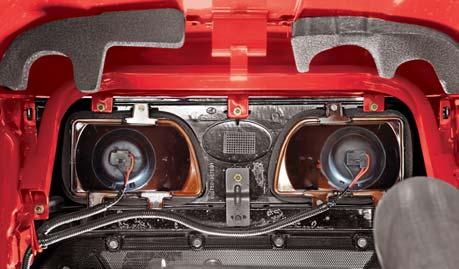
4.Using the tape on hood as a guide, sight across steering wheel and hood to locate tractor centerline. Mark tractor centerline (C) on wall.
5.From tractor centerline (C), mark a point (D) 6” (152.4 mm) out in each direction.
6.Turn light switch to dim position.

7.Locate point (E) of bright light projected by each lamp by adjusting screws (1), (2) and (3) as required. Cover other lamps, if necessary.


6 4

5
18 19
2 14 17
8
16
9
No.DescriptionLubricant
No.DescriptionLubricant 1 3 7 15 9 10 11 12
1Front Axle SupportCG
2Steering Stub Axle (LH)CG
3Steering Stub Axle (RH)CG
4Power Steering Cyl. Ends (LH)CG
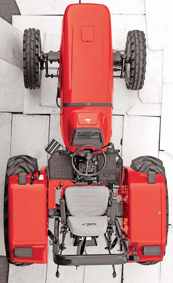
5Tie Rod (LH)CG
6Power Steering Cyl. Ends (RH)CG
7Tie Rod (RH)CG
8Clutch ShaftCG
9Brake ShaftCG
10Differential LockCG
11Levelling Rod (RH)CG
12Levelling Rod (LH)CG
13Bell CrankCG
14Roller Bearing at Front CoverCG
15Transmission Oil Filler PlugGO
16Transmission Oil Drain PlugGO
17Engine Oil FilterEO
18Engine Oil Drain PlugEO
General
Oil has a limited working life after which the effects of time, condensation, engine heat and by-products of combustion will combine to reduce its lubricating properties. It is therefore, detrimental to use a lubricant for more than the specified period. The intervals between lubricant changes detailed in this manual have been determined after prolonged tests and have been proved the most suitable for normal operation. In extremely arduous conditions, however, it may be necessary to reduce these periods and this point should be discussed with Mahindra tractor Dealer.
Oil can go bad while in the engine due to condensation and leakage of Diesel. Also running of engine in cold conditions may lead to such contamination.
Lubricant Storage
Tractors can operate efficiently only when clean oils are used Oils when stored shall be protected from dust, moisture and other contaminants. Store containers on their side to avoid water and dirt contamination. Please ensure that old and used oils are suitably disposed.
Alternate and Synthetic Lubricants
Conditions in certain locations may warrant usage of other lubricants than specified in the manual. In such cases the alternates may be used provided they meet the minimum performance levels specified. Synthetic lubricants may be used if they meet minimum performance levels specified in the manual. Manufacturers of these oils may be consulted for temperature applicability and suitability.
Bio-degradable oils and fuels are not advised.
Diesel Engine Lubricating Oil
Engine oil (for use in the crankcase) should be a well refined petroleum oil free from water and sediment.
Heavy duty oils are additive type oils possessing the oxidation-stabilising, anti-corrosive and anti-sludging properties necessary to make them generally suitable for high speed diesel engines. They provide the most satisfactory lubrication and should be used in diesel engines with present day diesel fuels. The quality of the base oil and the amount and type of additives used, determines their suitability for use in high speed diesel engines under severe operating conditions and also their suitability for use with diesel fuel containing sulphur or other injurious products.
Please note that engine breathes even while it is not running and once condensation take place rapid deterioration of oil may happen.
Hence idling time for the engine should not be longer than one year but it is advisable to check the oil after 6 months.
It is not the policy of the Mahindra & Mahindra Ltd. to guarantee oil performance under the conditions of operation, and its compatibility with the diesel fuels used, must remain with the supplier of the lubricant. High-speed diesel fuels and lubricants should be procured from a reliable source. When in doubt, consult your Mahindra tractor Dealer.
Mixing of Lubricants
It is generally advised not to mix different brands or types of oil.
Certain additives blended by the oil manufacturers to meet certain performance levels may adversely affect that of other brands causing compatibility problems.
NOTE : The term heavy duty as used here does not refer to the viscosity rating or “weight” of the oil.