
10 minute read
Do's & Dont's


(For Service & Maintenance)
DO’S - ECU (Electronic Control Unit)
DO-Ensure right terminals /connections are made to battery
DO-Check for condition of fuses, relay & wiring harness before replacing ECU
DO-Always use anti static mat, straps & gloves while handling ECU to avoid electrical overstress (EOS)
DO-Tightening torque of mounting screws to be maintained
DO-Ensure proper dataset is flashed into the ECU & also ensure proper dataset is selected while flashing into ECU.
DO-After mounting ECU, as soon as possible assemble the harness connector
DO-Ensure proper grounding / earthing. Ground line of ECU to be free from paints, dust
DO-Make sure there are no joints in the cable between PC/laptop and Diagnostic connector
DO-Ensure proper grounding / earthing
DO-Ground line of ECU to be free from paints
DO-Ensure no power interruptions, communication loss during flashing of dataset to ECU.
DO’S - Sensor (Engine Speed Sensor)
DO-Engine speed sensor must be removed from its packing just prior to installation in the vehicle.
DO-Sensor to be mounted by pushing it into place.
DO-First support of wire after connection: Max 250 mm. It should be on the sensor carrier.
DO-Replace damaged O-Ring.
DO-The storage area must be dry, dust-free and within the per missible storage temperature range.
DO-Clean and grease O-Ring prior to installation with mineral oil-based grease.
DO-Fix with only partially self-sealing cylindrical screw M6X12.
DO-Tightening Torque specification should be 8 ± 2 Nm.
DO-Storage temperature: -20ºC to 50ºC.
DO-Short-term storage temperature: -10ºC to 55ºC at 85%
DO’S - Sensor (Accelerator Pedal Sensor)
DO-Tightening Torque of the retaining screws should not exceed 9±1.5 Nm
DO-Use only self locking screws.
DO-After damage or in doubt of damage (e.g. dropped APM) the APM has to be separated and scrapped.
DONT’S - ECU (Electronic Control Unit)
DON’T-Avoid jump starting
DON’T-Do not allow part to fall
DON’T-Don’t try to dismount parts
DON’T-Avoid any damages to ECU while handling and assembly
DON’T-While ignition is ON, avoid removing or assembling sensors / actuators / ECU / ECU MAIN RELAY coupler
DON’T-Before removing ECU connector, wait upto 1 min after switching OFF the ignition key
DON’T-When vehicle is off-road, avoid using battery source for direct supply to FIE components
DON’T-Avoid short circuit with high current flow while welding, towing & servicing the vehicle
DON’T-Ensure no power interruptions, communication loss during flashing of dataset to ECU
DONT’S - Sensor (Engine Speed Sensor)
DON’T-Don’t drop the sensor.
DON’T-Direct sunlight must be avoided.
DON’T-The sensor is mounted by pushing it into place (not by hammering).
DON’T-Sensor should not be kept near any strong Magnetic Materials.
DON’T-Do not short circuit the connector pins while the sensor is functioning.
DON’T-Do not Hammer the sensor while fitting.
DON’T-Do not bend sensor wire with radius less than R = 50 mm.
DON’T-Angle between sensor exit and first support of wire should not be more than 90º.
DON’T-Sensor should not be kept near Hot medium or objects with Temp > 120ºC.
DON’T-None of the application guidelines should be deviated ( Air gap etc).
DON’T-Engine speed sensor must not be removed from its packaging until immediately prior to installation in the vehicle.
DONT’S - Sensor (Accelerator Pedal Sensor)
DON’T-Don’t drop the sensor.
DON’T-Do not exceed the maximum permissible tightening Torque.
DO’S - Sensor (Phase Sensor)
DO-Phase Sensor should be unpacked directly before installation.
DO-Sensor to be mounted by pushing it into place.
DO-Clean and grease O-Ring prior to installation with mineral oil-based grease
DO-First support of wire after connection: Max 250 mm. It should be on the sensor carrier.
DO-Sensor terminal pins should be free from water/ moisture.
DO-Fix with only partially microcapsuled screw M6.
DO- Tightening Torque specification should be 8±0.5 Nm.
DO-Parts as delivered to assembly shall be clean and free of debris, residual abrasive material and corrosion products affecting function or appearance.
DO-The storage area must be dry, dust-free and within the permissible. storage temperature range. Direct sunlight must be avoided.
DO-Before mounting coat the seal ring with mineral based oil lubrication.
DO-Storage temperature: -40ºC to +80ºC at 0…80% humidity for 4 years.
DO’S - Sensor (Coolant Temperature Sensor)
DO-Protect parts against rain, snow and solar radiation and store them dry and dust-free.
DO-Storage temperature is -30ºC to 60ºC with relative humidity 0 to 60%
DO-During service - After removing temperature sensor, existing Aluminum washer is to be carefully cut (without damaging the brass threading) and taken out.
DO-Replace the washer with Copper washer
DO’S - Sensor (Boost Pressure Sensor)
DO-Don’t drop the sensor.
DO-Do not Hammer the sensor while fitting.
DO-Do not short circuit the connector pins while the sensor is functioning.
DO-The pressure sensors have to be stored in their original packaging
DO-The storage temperature: 0°C … 40°C with relative humidity: 40% … 60% for maximum 3 years.
DO-The sensor must be protected against external affect (e.g. - precipitation, vapour). It has to be ensured that the O-ring will not be damaged at assembly.
DO-Sealing surface should be lubricated slightly (eg. non-acid paraffin oils like e.g. ‚Shell Ondina‘. Don’t use silicone based lubricants.
DO-While changing a Boost pressure sensor take care that both sensor and wire harness connector parts stay clear of moisture or dirt.
DONT’S - Sensor (Phase Sensor)
DON’T-Don’t drop the sensor.
DON’T-Do not Hammer the sensor while fitting.
DON’T-Do not bend sensor wire between the connection and the first support.
DON’T-None of the application guidelines should be deviated ( Air gap etc).
DON’T-Sensor should not be kept near hot medium or objects with Temp > 160 ºC.
DON’T-The installation is made by pressing in and not forcing in with blunt instrument (e.g., hammer).
DON’T-The Phase sensor should be unpacked directly before installing in the car or on the test bench.
DON’T-Do not touch the sensor pins or the wiring harness pins with hand (to avoid ESD).
DON’T-If the sensor is taken out of its installation bore after having operated under thermal and mechanical loads, it is not allowed to put the same sensor back in the installation bore. Instead, it has to be replaced by a new sensor in order to ensure tightness.
DON’T-Mount sensor by pushing in (not knocking, no tools allowed) until seat of flange.
DONT’S - Sensor (Coolant Temperature Sensor)
DON’T-Don’t drop the sensor.
DON’T-Do not exceed the maximum permissible tightening torque is 25Nm.
DONT’S - Sensor (Boost Pressure Sensor)
DON’T-Temperature of mounting area should not exceed 130deg.
DON’T-NOx level @ mounting position should be less than 200ppm
DON’T-In case of O-ring is damage, replace the sensor
DON’T-The sensor must not be mounted with striking tools (e.g. hammer)
DON’T-The pressure sensor must not fall to concrete ground from more than 1m height, nor be exposed to pushes which are comparable to this stress.
DON’T- Introduction of foreign substances into the pressure port, except for those substances found in normal operation, must be prevented. A contamination of the interior of the connector interface must be avoided.
DON’T-During disassembly from vehicle, the O-ring has to stay with DS-S3.
DON’T-For reinstallation of the same DS-S3/TF, only a clearly undamaged O-ring may be used again.
DON’T-Dust, water or other corrosive fluid must not enter into the connector interface.
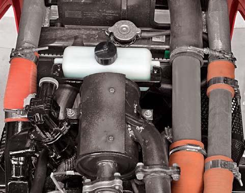
Cooling System
The cooling system consists of :
A.Radiator
B.Hoses & Connections
C.Recovery Bottle
D.Thermostat
E.Belts
F.Water Pump
G.Fan
To ensure an even temperature within the engine, the cylinder head and cylinder walls of the engine are water cooled. This water is in turn cooled in the radiator. The water is circulated from the radiator to the engine and back through the radiator by means of a water pump.
Radiator
The radiator consists of a cluster of hollow tubes enshrined into a number of fins and enclosed at both ends vide a Top Tank and a bottom tank.
Air sucked by Fan passes through the radiator fins thereby cooling the coolant flowing through radiator tubes.
The fins should be kept clear of mud or dirt accumulation. Over heating may be caused by bent or clogged radiator fins. If the spaces between the radiator fins become clogged, clean them with compressed air or coolant blown from engine side.
Radiator Cap
A pressurised radiator cap is provided which is set at 13 psi (0.9 kg/cm2) pressure. This cap ensures better cooling and avoids loss of coolant due to evaporation. It also reduces corrosion in engine sleeve & crankcase, hence it is strongly recommended that the engine should not be run without radiator cap. Also ensure that rubber gasket is intact & perfectly sealing the system pressure.
Surge Tank
When the engine is in operation, certain amount of coolant passes out of the radiator overflow pipe. This coolant is not allowed to escape into the atmosphere and captured into a surge tank.
When the engine is not operating and the coolant cools down, certain amount of coolant comes back into the radiator from surge tank. The surge tank thus helps to prevent loss of coolant.
Thermostat
This device prevents coolant circulating through the radiator until the engine reaches its operating temperature. With the thermostat closed, the coolant circulates only through the engine block.
It is important that if the thermostat is defective, do not attempt to repair it, replace with new. When installing a new thermostat, ensure the valve is facing upward. The thermostat operating temperature is 1800F (820C).
When straightening bent fins be careful not to damage the tubes or to break the bond between the fins and tubes.
The cooling system operates under pressure. It is dangerous to remove the radiator cap while the system is hot.
Always turn the cap slowly to the first stop, and allow pressure to escape before removing the cap completely.
Do not run the engine when the cooling system is empty, and do not add cold coolant or cold antifreeze solution if the engine is hot.
Do not run the Engine without Thermostat Valve.
Water Pump
The water pump is provided with a sealed bearing. Adjusting or greasing will not be necessary.
Hose Connections
Check periodically to ensure all the connections are in good order and the clips are tight. A leaking connection results in loss of coolant and thus engine efficiency. When using antifreeze in the cooling system, it is absolutely essential to have efficient connection so check these and should there be any doubt as to their serviceability, renew.
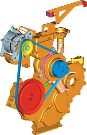
Fan & Fan Belts
A 11 Blade plastic fan is mounted on water pump and is driven vide fan belt by the main drive pulley. While the engine is in operation, the fan sucks air through the radiator core.
Slippage of belt on pulley can cause over heating. The Fan belts shall always be dry and free from oil or Grease. Incorrect belt tension results in its rapid wear. Main drive pulley is assembled on a roller bearing mounted shaft. Grease nipple is provided on front cover to grease the bearings. Grease the bearings every 600 hrs. of operation.
Belt Adjustment
To adjust belt tension, loosen the alternator on the adjustable bracket and lock the bolt in the location that gives correct belt tension (270-320 N) such that the belt can be depressed without much effort by the thumb, 0.25 to 0.4 inch.
Belt Removal
1.Loosen the Nut (C).

2.Push the alternator down.
3.Ease the fan belt off the alternator pulley.
4.Ease the fan belt off the main drive pulley.
5.Slide out the belt from water pump pulley over the fan blades.
Belt Replacement
Reverse the procedure of fan belt removal stated above. Adjust the fan belt tension as previously detailed.
Draining the System
Two drain plugs must be opened. One is on LH side of crankcase and one on radiator bottom tank. To speed up draining, remove the radiator cap. Ensure that the drains are not clogged. Close the taps after draining is complete.
Cleaning out Dirt and Sludge
Drain cooling system as directed above. Fill the cooling system with solution of water (90%) and ordinary baking soda (10%) by volume.
Do not refit the radiator cap. Operate the engine until the coolant is hot. Drain, flush with clean water and refill with a rust inhibitor or anti-freeze solution.
A. Alternator Mounting
B. Alternator
C. Adjusting Nut
D. Adjusting Bracket
NOTE: Under normal conditions use Lithium based NLGI-2 grease with EP additives. Contact your Mahindra dealer for grade of grease to be used under extreme ambient conditions.
Adding Coolant to the System
Allow the engine to cool if it is hot.
1.Open the Hood.
2.Remove the radiator cap.
3.Fill the radiator from fill neck (A) with clean coolant upto a level approx. 2" (5cm) below the radiator neck.
4.Start the engine and let it idle to remove air from the system. Coolant level in radiator will reduce.
5.Slowly pour coolant into the radiator till the coolant level in radiator does not go down further.
6.Fill coolant in surge tank from fill neck (B) upto the Max level mark.
7.Refit the radiator cap.
8.Shut down the Engine.
9.Close the Hood.
Ensure that the filler cap is clean and free of dirt particles before replacing.
Cooling System Protection
A common cause of the engine overheating is a rust clogged cooling system. Rust causes overheating by interfering with circulation and cooling. The tractors are filled with a mixture of new low silicate antifreeze (50%antifreeze - 50% water) with a rust inhibitor in it. Use of approved supplemental corrosion inhibitor along with ethylene glycol will add increased rust prevention, reduce scale formation, minimize cylinder wall erosion and reduce foaming or tendency to foam.
Antifreeze : There are numerous antifreeze products marketed today. Diesel engines are adversely affected by the additives added to protect the aluminum surfaces. Antifreeze suitable for diesel engines conforms to an industry recognised standards which limits silicates to 0.1%. Once silica-gel has formed it is very difficult and costly to remove.
Low silicate antifreeze is available through out the United States. We are listing below some low silicate antifreezes that meet GM 6038 M formulation specification. There may be other suppliers who can make available low silicate antifreezes.
Recommended change period : 1 year or when ever the radiator coolant is drained.
No.CompanyProduct
1.Texaco (1)2354 / 2055
Startex (Was JC-04)
2.BASF WYANDOTTE241-7
3.ShellShellZone-LS
4.InternationalI.H. Antifreeze Harvester
5.Old Water TradingFull Force
6.ConocoFleet Antifreeze
7.NorthernAll Weather (NPC 220) Petrochemical
NOTE :
% Anti Freeze/% Water50/5060/40
Freeze Protection-34 0F-64 0F -36.67 0C-53 0C
Boil over protection+265 0F+275 0F 1290C135 0C
(with 13 psi (0.91kg/cm2) radiator cap)
Recommended change period : 1 year or when ever the radiator water is drained.
Adjusting The Valve Clearance
After the first 1000 hrs. the cylinder head bolts should be re-tightened to a torque as recommended. The bolt in the center should be tightened first and then work outwards. Check the valve clearance as given in specifications. Following this a further check should be made after every 1000 hrs.
1.Remove the valve housing.
2.Turn the engine until the No. 1 cylinder is at the top dead center of the compression stroke.
3.Loosen the locknut and adjust the screw in each valve lever so that the feeler gauge slips snugly between the ends of the valve lever and the valve stem.
4.Tighten the locknut and re-check the clearance.
5.Crank the engine for 2/3 revolutions in case of 3 cylinder engine in order to bring the TDC position of subsequent cylinder number as per the respective firing orders. Now adjust the valve clearance as explained earlier.
Repeat the process until clearance for each set of valves is adjusted.
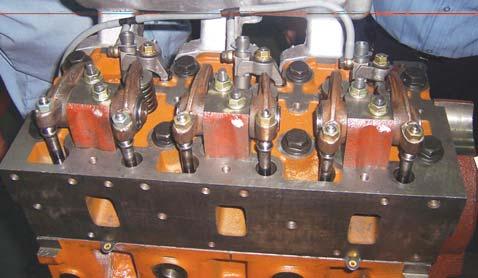
Replace the valve housing and ensure that the valve housing gasket makes an oil tight seal with the cylinder head. Use a new gasket, if necessary.
Be accurate - use a feeler gauge for checking the valve clearance.