14 minute read
Controls


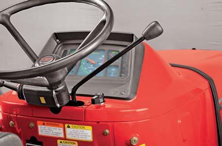
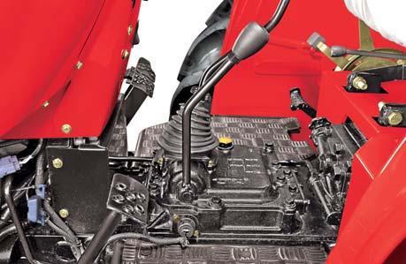
Hand Throttle Lever
Use the Hand Throttle Lever (A) to set a constant engine speed for stationary operation or for field operation wherever desired.
Increasing Engine Speed : Pull throttle lever towards operator.
Decreasing Engine Speed : Push throttle lever away from the operator.
Constant Speed Setting : Certain operations may require a particular engine speed. This can be achieved by resting the Hand Throttle Lever in a position where you get the desired engine speed.
Foot Throttle Operation
When tractor operation requires repeated speed change, use the foot throttle pedal (B) to temporarily increase engine speed above hand throttle setting. We recommend to keep the hand throttle at minimum and use foot throttle when driving on highway a.Set the hand throttle lever at desired rpm. b.Depress foot throttle pedal to Increase Engine rpm. c.Release foot throttle pedal to decrease Engine rpm to achieve the previous engine speed set by hand throttle lever.


Dual Clutch
Constant running P.T.O. with dual clutch is offered as a standard feature on Mahindra 4565 tractors. This has a speed of 540 rpm @ 2059 engine rpm.
It has two clutch plates and two pressure plates which work in two stages of pressing the clutch pedal. When the clutch pedal is depressed to the first stage, the drive of engine to main gear box gets disconnected, while the P.T.O. output shaft (if engaged) will continue to be driven by the engine.
When the clutch pedal is depressed further to second stage, the drive to the PTO shaft also gets disconnected.
While changing transmission gears, it is necessary to depress the clutch pedal only up to the first stage. This will not affect the drive to the P.T.O. shaft. If it is required to stop the tractor but keep the P.T.O. running, only depress the clutch pedal through the first stage. This has great advantage while using PTO driven equipment. If an extra load is encountered, the forward movement of the equipment can be halted while still permitting full power to be available at the P.T.O.
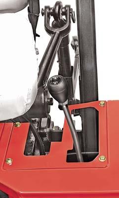
High-Low Range Selection Lever
This lever is used to select the high or low speed range which has the effect of doubling the number of available gear ratios for a tractor.
High Gear: Push the lever Rearward.
Low Gear: Push the lever forward.
Neutral: Keep the lever in central position. A safety neutral switch is provided on the transmission high-low range selection lever for the safety of operator. The starter will not activate unless safety neutral switch is operated. Only when the hi-low range selection lever is in neutral position, the safety neutral switch will be activated causing the electrical circuit to complete and starter motor to crank.
Gear Shifter Lever
This lever is used to select any one of the four forward & one reverse gear ratio. The positioning of gears for Mahindra 4565 tractors is as depicted.
Refer Chart for road speed of tractor in different gears.
Chart for road speed of tractor for 14.9 x 28 tyre as per rolling radius 0.659m
To prevent inadvertent tractor movement, avoid accidental contact with the gearshift levers. Always stop the engine, firmly apply the parking brake and place all transmission levers in neutral before leaving the tractor.
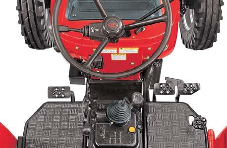
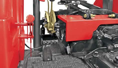
Brakes
Two independent brake pedals are provided for LH and RH wheel braking to enable sharp turns during field operations.
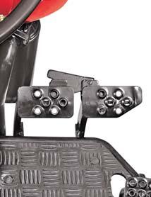
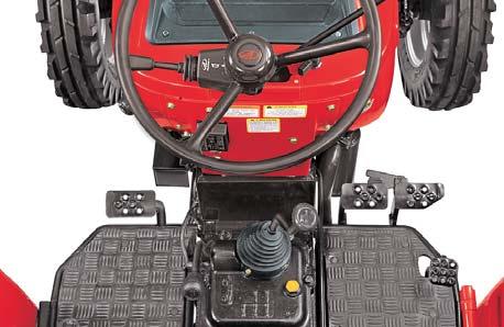
To make a sharp turn to the right, depress RH brake pedal (B).
To make a sharp turn to the left, depress LH brake pedal (C).
The brakes can be latched together to act simultaneously by means of brake pedal latch (A) as follows,

1.Rotate brake pedal latch (A) clockwise until it locks into RH brake pedal (B).
2.Depress any of the brake pedal to slow or stop the tractor.
3.When brakes are applied with brake pedals latched together, the tractor should stop in a straight line. Check and adjust brake settings if the tractor is dragged to either side on applying brakes.
The Hand Throttle Lever should be brought to low idle rpm position before applying brakes.
Using unlocked brakes to stop the tractor at high speeds may cause accidental turning or tipping.
Lock pedals together when not using the turn brakes or for road travel. Slow down before making a turn. Do not apply independent brakes while an attachment is engaged with the ground. This can cause damage to the attachment, three point linkage of tractor and may also result in tipping of the tractor.
The “balancing” of the braking system should be checked every week, or whenever the tractor is taken on the road after working extensively or when one brake is used more often than the other. If this precaution is not taken an accident may occur.
Hand brake should only be used for parking purpose.
Parking Brake Lever
The Parking brake lever (A) is provided on R.H. side of operator’s seat.

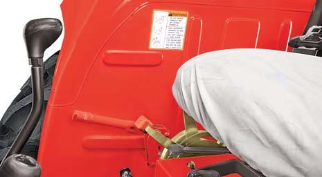
For applying the parking brake :
1. Press the foot brakes fully.
2. Pull the hand brake lever top side in vertical position. For releasing the parking brake :
1. Push the lever to front side in horizontal position.
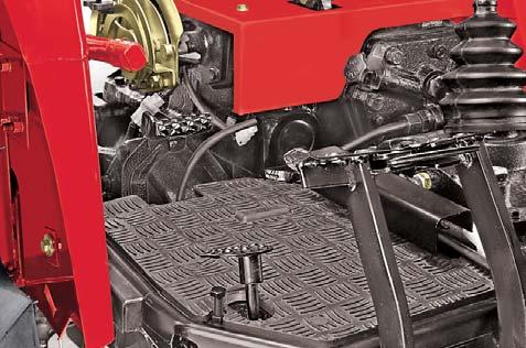
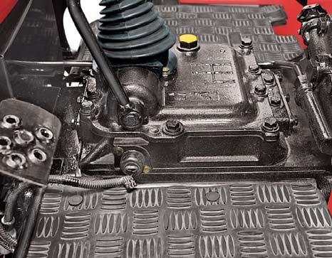
Differential Lock Pedal
Differential lock pedal (B) located on the R.H. side of the Operator’s Seat when depressed by heel pressure, operates a differential lock mechanism which locks both of the axle shafts together. Its purpose is to overcome completely the one-wheel slip encountered under bad field conditions, especially when plowing or when hauling heavy trailers on slippery surfaces.
The condition where one wheel spins completely uselessly digging itself Into the soil while the other stands idle, is thus overcome resulting in saving fuel, brake wear and tire abuse.
Differential lock is designed for occasional use. Do not attempt to lock differential while, a.The tractor is in high speed. b.Turning tractor.

Releasing the heel pressure disengages the differential lock.
The Differential Lock design is solely for the use with pneumatic tires. If steel wheels, girdles etc. are fitted, the differential lock should be removed as a precaution.
Attempting to turn the tractor while differential lock is engaged may result in damage to transmission.
Power Take Off
1.Move hand throttle lever to the low idle position.
2.Depress the clutch pedal fully.
3.Engage the power take-off shaft by moving the lever to the rearward position.

4.Engage the desired tractor gear (this does not apply if the tractor is to remain stationary).

5.Move throttle to obtain required power.
6.Release the clutch pedal gradually.
To change gears without stopping the power takeoff shaft, depress the clutch. Change gears in the normal manner and release the clutch.
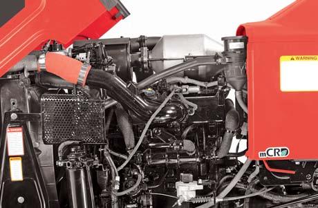
Opening the Hood
The hood is hinged at the front side and opens away from the operator as follows.
1.Turn the lever (A) on one side of the hood.
2.Turn the lever (A) on other side of the hood.
3.The hood will unlock from lock (B).
4.Turn the hood upwards by hand.

5.Rest the hood in fully open position.
Closing the Hood
1.Push the Hood downwards.
2.Turn the lever (A) on one side of the hood.
3.Press the Side of Hood against the Tractor gently.
4.Release the lever (A) ensuring that it locks into the hood.
5.Repeat the procedure for locking other side of hood.
Firmly apply the parking brake, place all gear shift levers in neutral and block all four wheels before operating any stationary PTO equipment.

Do not approach or work on the PTO shaft or equipment with the PTO in motion. Shut off the tractor engine and the PTO and wait for all movement to stop before working on the PTO or equipment.
Do not operate PTO in high range for tractors.

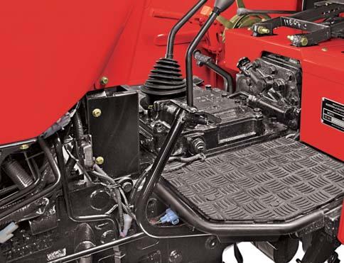
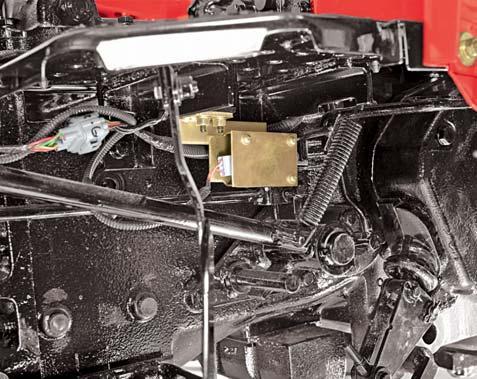
PTO Neutral Switch
This switch is located under the LH Footplate. The starting circuit of the tractor is connected through this switch which becomes operative to complete the starting circuit only if the PTO lever is disengaged.
This switch thus ensures that engine can be started only when PTO lever is in disengaged position. This feature hence gives additional safety near PTO.
Consult your Mahindra tractor Dealer if your safety starting switch malfunctions.
Transmission Neutral Switch
This switch is located on the High-Low Range Selection System. The starting circuit of the tractor is connected through this switch which becomes operative to complete the starting circuit only if the High-Low Range Selection Lever is in neutral position.
This switch thus prevents accidental starting of the tractor in gear.
Consult your Mahindra tractor Dealer if your safety neutral switch malfunctions.
Do not bypass the PTO Neutral switch.
Do not bypass the Transmission Neutral switch.


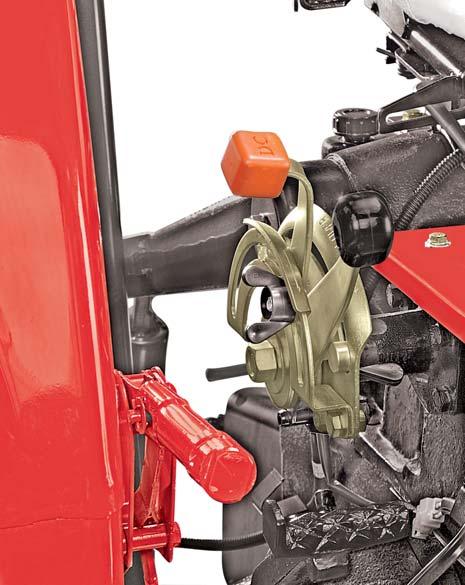
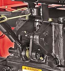
Full Live “Vary-Touch” Hydraulic System
The tractor is fitted with a completely self-contained and fully “live” hydraulic system. Using a pump driven directly from the Engine, it is able to operate the three-point linkage or external tapings, independent of any clutch movement when changing gear or operating the power take-off.

This system incorporates the following
1.Position control (A)
2.Draft control (B)

3.Isolating valve (C)
All these controls are within easy reach of the operator. The upper limit stop is set at the factory and serious damage will result if this is altered in any way.
Position Control Lever
This lever controls the lifting and lowering of all implements used on the three point linkage.
1.The lever is moved Forward to lower the implement.
2.The lever is moved Backward to raise the implement.
Draft Control Lever
This lever is used to set the amount of load which the tractor has to pull irrespective of ground contour, soil conditions, or the pitching of the tractor.
The lever is moved Forward to deepen the implement and Rearward to shallow it.
Isolating Valve a.Lift the implement to maximum height vide PC lever. b.Loosen the locking bolt (B). c.Turn the lockplate (C) outwards. d.Turn the Knob (A) in clockwise direction fully. e.Tighten the locking bolt (B).
While carrying implement on a tractor for a longer distance it is essential that the implement does not drop down suddenly due to inadvertent movement of PC lever. An Isolating Valve provided on the tractor serves this purpose and can be used as follows.
The implement now cannot be lowered vide lowering the PC Lever and hence can be transported safely for longer distances.
For lowering the implement when desired, a.Turn the Knob (A) in anticlockwise direction fully. b.Turn the lockplate (C) inwards. c.Tighten the Locking bolt (B). d.Lower the implement vide PC lever.
Ensure at all times that both the draft & the position control levers slide just adjacent to their respective quadrants with minimum clearance.
Position Control
This lever (A) controls the lifting and lowering of all implements used on the three point linkage.
1.Moving the lever Forward will lower the implement.
2.Moving the lever Rearward will raise the implement. The control can also be set by PC stop screw (B) to govern the height of out-of-ground implements such as mowers, rakes etc., so that the implement can be lowered to exactly the same height at the commencement of each run.
PC lever (A) should be used for the following applications:

1.TRANSPORT of implements and turn around at the end of the field.
2.CONSTANT DEPTH of implements on level terrain and for non-ground engaging implements such as spreaders or sprayers. Place the PC lever at desired depth.
Position Control Lever Stop
1.Move the DC lever (C) to its most forward position.
2.Move the PC lever (A) back to the upper limit and allow the implement to lift fully.
3.Move the PC lever (A) forward until the implement has reached the desired working height.
4.Set the position control stop screw (B) against the PC lever & tighten the knob.
Whenever the lever is returned to the stop from the lift position, the implement will return to and remain at the preset height.
The operator must be thoroughly acquainted with the location and use of all controls regardless of experience, must read this section carefully before attempting to operate the tractor.

Never move the position control lever beyond the upper limit stop.
Draft Control
As the draft of the implement varies due to irregularities of ground contour, soil texture, or pitching of the tractor, so the load on the top link of the three point linkage will vary. These changes are transferred through the internal mechanism into hydraulic valve movement. By means of the top link, the draft control system reacts not only when the top link is in compression, as is usually the case, when plowing, but also when the top link is in tension, as with shallow working implements. An increase in implement draft will increase the compression or reduce the tension on the top link and the system will go to lift. Conversely, a decrease in implement draft will cause the system to go lower.
Due to setting of the draft control lever, the load required to maintain the valve in the hold position is governed. Therefore, the load the tractor has to pull is maintained irrespective of ground contour, soil conditions, or the pitching of the tractor.
The lever is moved Forward to deepen the implement and Rearward to shallow it.
Setting the Draft Control
1.Move the DC lever (B) to its most forward position.
2.Move the position control stop screw (C) to the front of the quadrant and lock it.
3.Lift the implement off the ground by pulling the PC lever (A) back to upper limit.
4.Lower the implement into work by moving the PC lever (A) to its most forward position. The faster the lever is moved Forward the quicker the implement will drop.
5.Move the tractor slowly in forward gear. When the implement has reached the desired working depth, move the draft control lever rearward, until the linkage begins to lift, due to the load on top link. This will be the position of the lever for that particular depth in a particular type of ground.
6. Having obtained a desired setting move DC Stop screw (D) until it touches the DC lever (B) and lock it in this position. When the soil texture remains constant, the implement is partially carried on the three point linkage. Therefore, proportion of the implement weight is transferred to the tractor rear wheels to improve traction. When a condition arises which causes an increase in draft, the system will go to lift and all the weight of the implement will be transferred to the tractor rear wheels to provide maximum traction. As soon as the draft returns to normal, the system goes to lower position and the situation returns to its former condition.
When the front wheels of the tractor drop into a furrow, the tendency for the implements is to lift out of the ground. As the implement lifts, the draft decreases and the system goes lower to maintain the pre-set depth. If the rear wheel drops into a furrow, the reverse will occur. Thus under all operating conditions, the “Vary-Touch” system provides maximum traction and constant implement depth.
Do not transport or attach equipment when the hydraulic system is in Draft Control. Use Position Control for these operations. Always lower hydraulic equipment to the ground before stopping the Tractor.
Under No Circumstances must the Draft Control Lever be used to lift the implement to its uppermost position. To do so will cause overheating of the system.
All movements into and out of the soil must be made by using the Position Control lever.
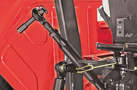
Toplink

It is used to attach the implement and control its inclination front-to-rear with respect to ground. The distance between its two ball-joints can be increased or decreased by rotating the turn-buckle as follows.
1.Loosen the locknut (A).
2.Clockwise rotation of turn buckle (B) will decrease the distance.
3.Anticlockwise rotation will increase the distance.


4.Tighten the locknut (A) after desired adjustment.
Draft Sensing Bracket
Draft sensing bracket transfers the toplink force to the draft sensing mechanism.
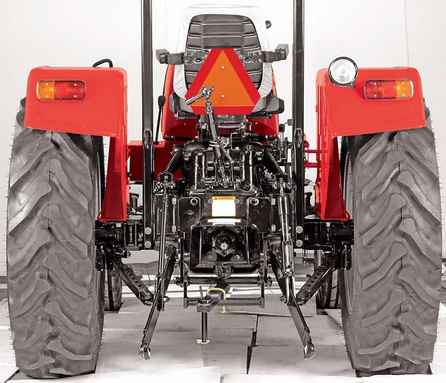
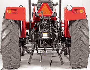
Lower Links
The Lower Link is available for Cat–I with adaptability of Cat–II implements.
Lower Link Hitch Point
Two positions to which the lower links can be attached are provided. The upper hitch pins should normally be used for three point linkage equipment, but improved penetration and lift height can be obtained when the lower hitch pins are used.
Adjustable Lift Rods

Use turn handle (A) on the adjustable lift rod to raise or lower the lower link for side-to-side levelling of implement with respect to ground.
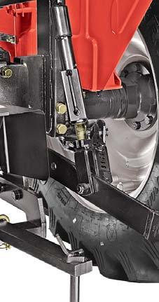
1.Raise lift rod turn handle (A) out of locking tab (C).
2.Rotate turn handle (A) clockwise to raise the lower link or anti-clockwise for lowering.

3.After adjustment, make sure to engage the box (B) with locking tab (C). Always transport the implement with turn handle in this position.
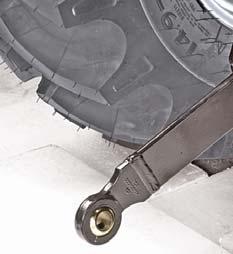
Lateral Strut Stabilizer
These are provided to prevent both lower links fouling with tires. Its Length can be increased or decreased for adjustment according to varying implement’s spans.
Attaching Implement
Hitching is made easy if the implement is left standing on level ground. Attach the implement as follows.
1.Place the tractor central and square with implement.


2.Slowly back tractor into position and align the LHLower link (B) with implement pin.
3.Attach the LH lower link (B) and secure it with cotter.
4.Park tractor safely.
5.Attach the RH lower link (C) using the turnbuckle adjustment to align with implement pin and secure it with cotter.
6.Attach the top link (A) to the implement using the turnbuckle adjustment to align the holes and install the implement cotter.
7.Start the engine and lift the implement.
8.Adjust the implement and its inclination front-to-rear with respect to ground.
NOTE : When hitching a plow or out of ground implement, the lift rods should be in the fixed position. When hitching wide implements, such as cultivators, disc harrows etc. which should remain levelled irrespective of the altitude of the tractor, the LH lift rod should be in the slotted position. This will permit the tractor and implement to move laterally, independent of another.
With the rigid left hand lift rod there should be one inch of thread view when the two parts are screwed together. With the telescopic left hand lift rod the two parts should be screwed up to the shoulder then unscrewed one full turn.
Lower Links
The lower link is available with adaptability of Cat–I and Cat–II implements.

Provision is given in the eyeball of lower link for Cat-I and Cat-II implements.
The eyeball shall be rotated in the lower link for appropriate implement pin size.
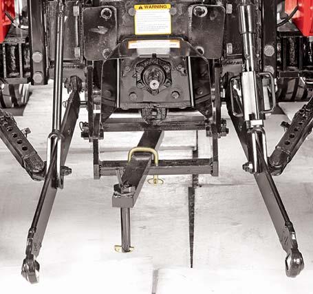
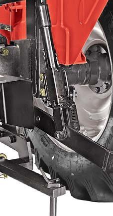
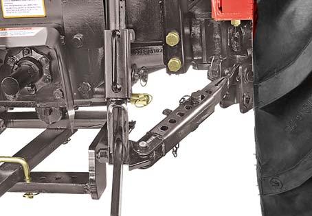
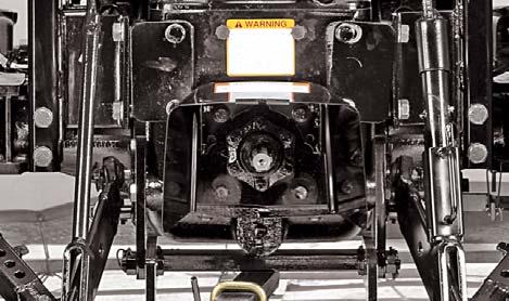
Swinging Drawbar
Tractor can be equipped with a drawbar for connecting to pull behind implements. It can swing from side to side. Certain heavy equipment such as a loaded single axle trailer can place excessive strain on the drawbar. Strain is greatly increased by rough road and high speed.
The drawbar must be locked in center position when
1.Operating a drawbar pulled PTO driven implement.
2.Towing implements / Trailers on road or field.
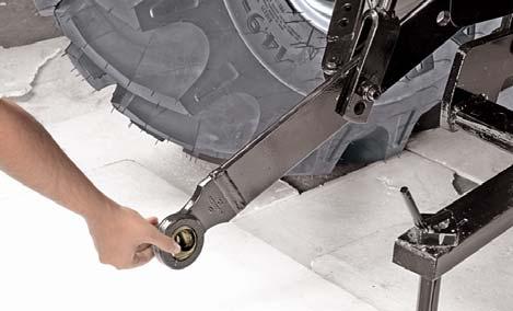
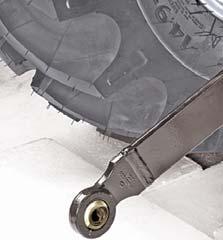
Using Swinging Drawbar
1.Remove "U" bolt (A).
2.Shift to the drawbar (B) to next hole as desired.
4.Lock the "U" bolt (A).
5.See your implement operator’s manual for drawbar positions.
Attaching PTO Driven Implement
1.Turn Key to "OFF" position.
2.Disengage the PTO lever.
3.Position the drawbar according to the requirement of implement and drive line.
4.Attach implement to tractor before connecting PTO driveline. Raise Hitch upwards if it is not to be used.
5.Rotate PTO shield (C) upward for clearance.
6.With the engine still OFF, turn the shaft slightly by hand if necessary to line up splines. Connect driveline to PTO shaft. Pull out on shaft to be sure drive line is locked to PTO shaft.
7.Place PTO shield in downward position. Rear roll-over can result if pulling from wrong location on tractor. Hitch only to drawbar. Use 3 point hitch only with implements designed for its use, not as a drawbar.
Try to balance the load primarily on the implement wheels. Avoid overloading the drawbar. Add Jerrycan weights for improved stability. Engage the clutch smoothly, avoid jerking and use brakes cautiously to avoid jackknifing.
Always secure the drawbar to prevent swinging when transporting equipment or when operating any but ground engaging equipment.
Do not pull from the lower links with the links above the lowest position. Always use the drawbar or lower links in the lowered position for pull-type work, otherwise the tractor may overturn rearwards.