6 minute read
l System


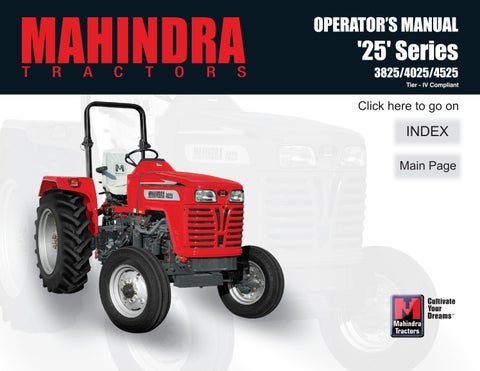
Alternator
Following checks of alternator charging system will avoid many problems that might otherwise develop.
1.Check belt tension. Refer your operator's manual for proper belt tension.
2.Keep pulley nut tight.
3.Check alternator terminals and cable connections for good condition, secure fastening and freedom from corrosion.
4.Check battery cables and connections for good condition, secure fastening and freedom from corrosion.
5.If battery will not take adequate charge, or is otherwise unsatisfactory replace battery.
Charging Circuit
Should the battery be in a low state of charge, which will be shown by lack of power when starting or poor lights. This may be due to either alternator not charging or giving lower intermittent output, then proceed as below :
Check Battery Charging Indicator when the engine is running steadily at working speed.
If the Battery Charging Indicator glows, have the equipment checked by your Mahindra tractor Dealer. Inspect alternator drive belt and adjust as necessary. Examine the charging and field circuit wiring, tighten any loose connections, replace any broken cables, pay particular attention to the connections.
Note : Alternator Maintenance should be done by authorised Dealer. Too tight a belt will cause rapid wear of belt and damage to bearings.
A slack belt will not drive the Alternator, and therefore the battery will not be charged.
Starter Motor Removal
1.Disconnect the battery to starter solenoid coil cable, earth cable from the battery, Key Switch to solenoid coil cable.
2.Remove the mounting bolts and withdraw the starter motor. To install the starter motor, reverse the above procedure.
To avoid damage to alternator charging system, service precautions should be observed as follows.
1.Never make or break any of the charging circuit connections, including the battery when engine is running.
2.Never short any of the charging components to ground.
3.Do not use a jumper battery of higher than 12 volts.
Always disconnect the battery ground cable before carrying out arc welding on the tractor or any implement attached to the tractor. Use only specified cable for replacement
Should the starter motor be removed, and a replacement motor or drive end bracket be fitted, a check must be made of the out of mesh clearance after assembling the starter motor to the engine. The dimension between the leading edge of the pinion and the engine flywheel should be no less than 0.32 cms.
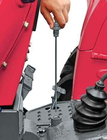
Filling and Air Bleeding for Power Steering System for 4025 & 4525
Open the dipstick cum filler (A).
1.Fill the reservoir with recommended oil up to the upper level mark on the dipstick cum filler (A).
2.Start the engine using start key and immediately stop it by turning the key to the stop position.
3.Check the oil level and refill oil such that the level is between upper and lower level marks.
4.Repeat this procedure three times, each time checking level and refilling the reservoir if required.
5.Start the engine and let it idle for 2 minutes.
6.Shut the engine off and check the fluid level in the reservoir again, top-up if required.
7.Start the engine and steer the vehicle from full left to full right positions five times. Check the oil level and top-up oil if required.
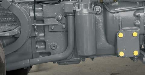
Replacing the filter element
Remove the filter elements initially at 50 hours and then subsequently every 1000 hrs.
1.Drain the oil in Power Steering System
2.Remove the four bolts (B).
3.Remove the cover plate (C).
4.Pull-out the filter element and replace with new one.
5.Replace the O’ Ring Between cover plate and housing.
Tips for maintaining the power steering system. Top up fluid level in reservoir as necessary. Maintain correct inflation of front tires. Always use a puller to remove the steering wheel. Do not use a hammer, torch or crow bar. Investigate and immediately correct any play, rattle, shimmy, or other unusual condition in the steering system.
Do not attempt to weld any broken steering component. Replace the component with original part only.
Do not cold straighten, hot straighten or bend any steering part.
Prevent dirt or other foreign matter from entering the hydraulic system. Clean off around filler caps before checking oil level.
Investigate and correct any external leakage in the steering system.
Comply with the manufacturers specifications for replacing the filter, first change after 50 hrs. and then 1000 hrs. subsequently.
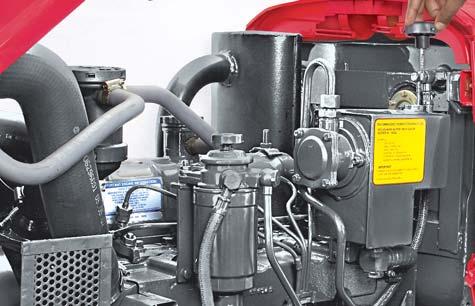
Front Axle - Front Wheel "Toe-in" Check
In the event of the tie rod setting being interfered with, then it is necessary to adjust the TOE-IN. Before measuring and adjusting the TOE-IN, ensure the front wheels are in the straight ahead position and the front axle is not tilted. After adjusting the front wheel tread and with all connections secured, the front wheels should have 0 to 3 mm TOE-IN.
Measure the distance between the outer edges of the wheel rims at the same height as the hub caps. Mark the point measured and turn the wheels one half revolution so that the marked points are at the rear. Measure again the distance between these two points and this distance must be the same as measured before without variance. To adjust the TOE-IN shorten or extend the tie rod by removing the left hand side tie rod bolt and screwing the rod clockwise or anti-clockwise.
Front Wheel Check
After the first 50 hours operation check the front wheel axle nuts for tightness. If these nuts are loose, re-tighten.
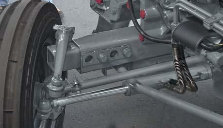
Greasing the Front Wheels
After every 400 Hrs. of operation replace the grease in front wheel hubs as explained below.
1.Jack the front wheels clear of the ground.
2.Remove the hub cap (A), remove split pin, castle nut (B) and washer.
3.Remove the bearing (C), (keep this bearing clean) and then remove the wheel.
4.Clean inside the hub (D). Remove the old grease from the bearings and retainers, clean with solvent and repack with Molybdenum Disulfide chassis lubricant.
5.Now reassemble in the reverse sequence.


Preloading Bearings
When replacing the front wheels it is essential that bearings are pre-loaded properly. To ensure this the nut 'B' should be tightened up while the wheel is being revolved until it stops. Slacken off the nut upto the first pin hole where the washer is free to move and place the split pin. It is advisable to leave the bearing (E) in place and clean with a brush and solvent. Before reassembling the bearings, repack the rollers with new grease.
When the TOE-IN adjustments have been made the tractor should be jacked-up and the axle tilted to its maximum tilt position. In this position the wheels should be turned to the full left-hand lock and at this angle the welded stop on the steering knuckle pivot pin sleeve should be hard against the stop on the steering knuckle.
The oil and reservoir is common for Transmission, Hydraulics and Steering.

Transmission Oil Level
Remove the dipstick cum breather (A) and check oil level. Refill oil from filler neck (B) till the required level.
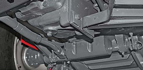
Transmission Oil Drain
A drain plug (C) is provided on the transmission for draining transmission oil.
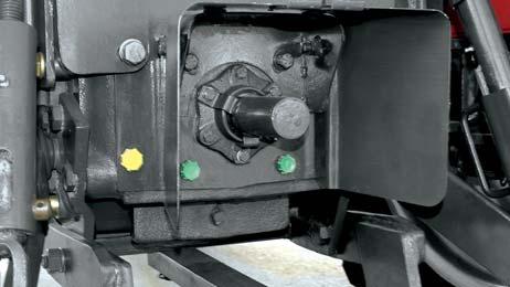
Hydraulic Suction Filter

The oil filter element (D) should be replaced initially at 50 hours and subsequently after every 500 hours of operation or whenever hydraulic oil is changed.

Transmission Strainer
Transmission strainer (E) should be removed and cleaned initially at 50 hrs. and subsequently every 1000 hrs.of operation or whenever the transmission oil is changed.
Clutch Pedal Adjustment
The clutch pedal should be adjusted to give a measurement (A) of 6.7” (17 cm) between the pedal pad and the foot plate.
Clutch Pedal Free Play
With the clutch fully engaged, the pedal should have a free movement (B) of 1/2" (1.25 cms).
The free movement is obtained as follows :

1.Loosen the retaining bolts (C)
2.Move the pedal round the clutch release shaft (D) until the required adjustment has been made.
3.Retighten the retaining bolts after adjustment.
Disc Brakes
The brakes consist of two actuating discs, two friction discs and operating linkages, enclosed in a brake housing. The two friction discs are driven by bull pinion/brake shaft, the speed of rotation of which is reduced by the engagement of the actuating discs when downward pressure is applied to the brake pedals. The actuating discs force the friction discs against the inner face of the brake housing and the outer surface of bull pinion cage.
Brake Pedal Adjustment
Adjust the brake as follows :
1.Loosen the jamnut (A) on the foot-brake adjuster bolt.
2.Tighten the nut (B) to tighten the brake and loosen the nut (B) to loosen the brake.

It is very important to ensure that both brakes have the same amount of free movement before taking hold. A definite way to check this equalisation is to jack up the rear wheels so that they turn freely. Start the engine and operate in 3rd or 4th gear. Application of the brakes should slow both wheels at the same time, and also tend to reduce engine speed. If, when the brakes are applied, one wheel stops and the other continues to spin, adjust the brakes until both wheels stop simultaneously with application of the brakes.
Brake Pedal Free Play

Measure free play of pedal stroke (C). Ensure free play is within specified limits. If free play is not within specified limits, adjust linkage as shown below. Free Play - Distance 3/4" (1.90 cms).