4 minute read
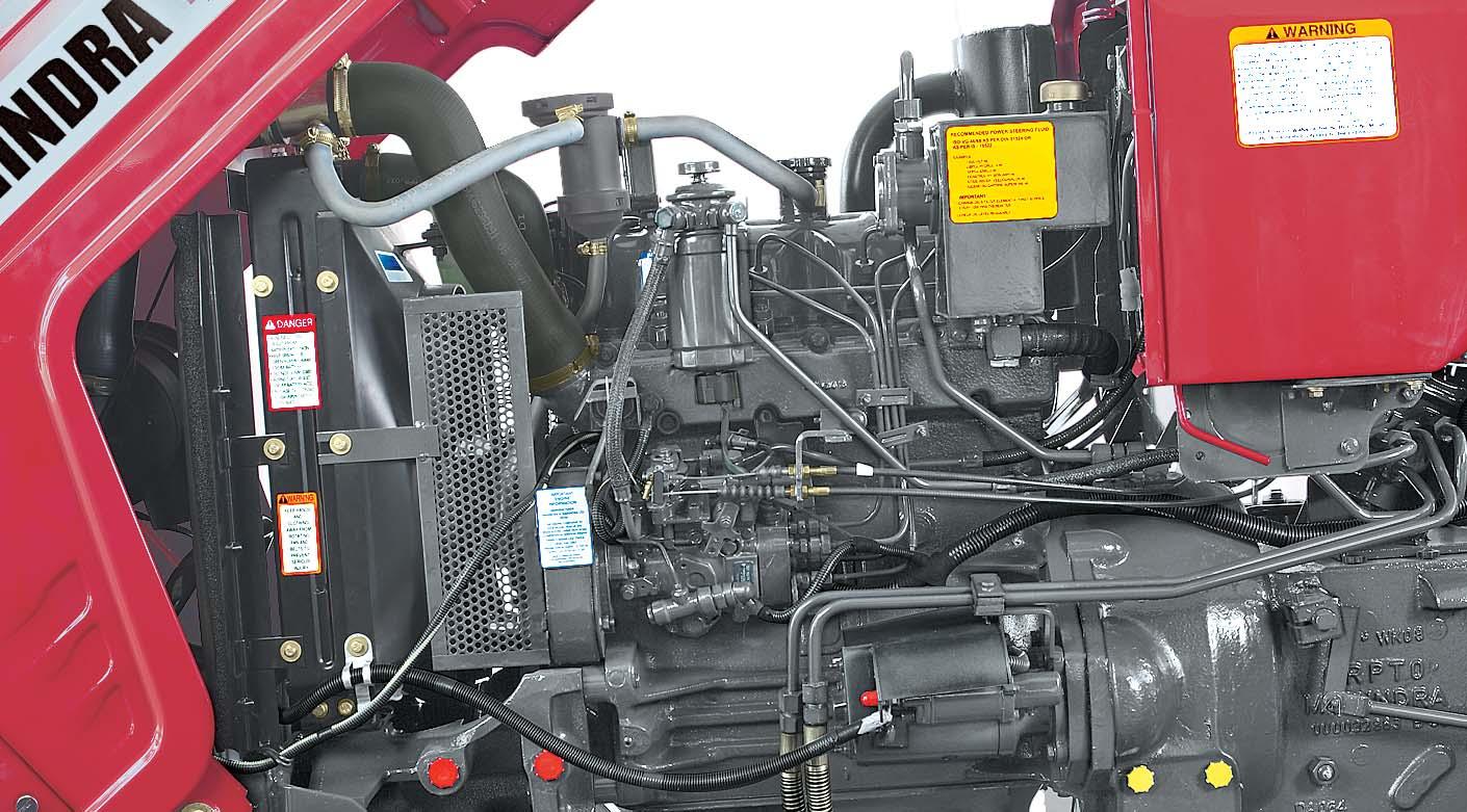
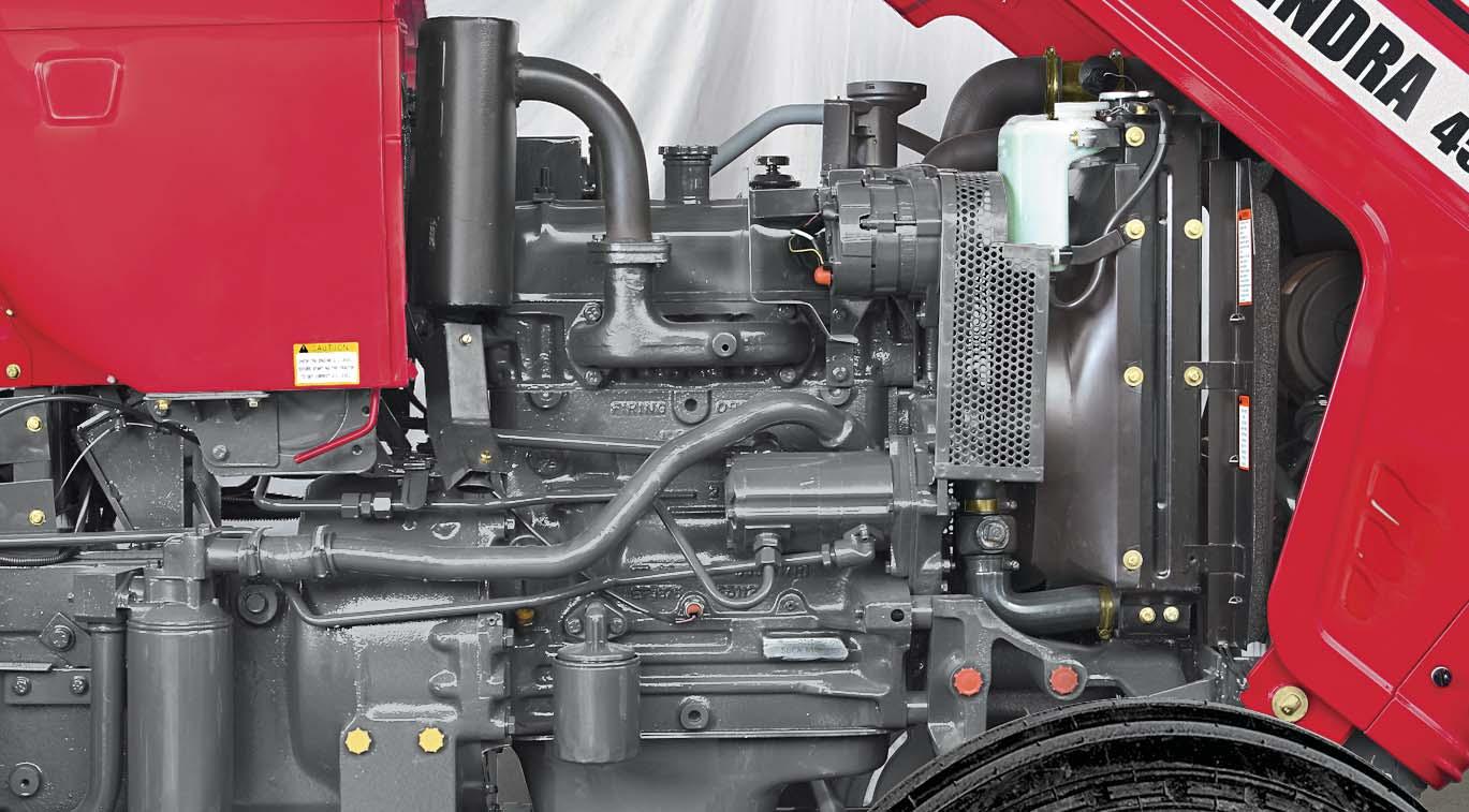
LH & RH View of Engine - Model 4025 & 4525


Lamps 3825, 4025 & 4525


Front View :
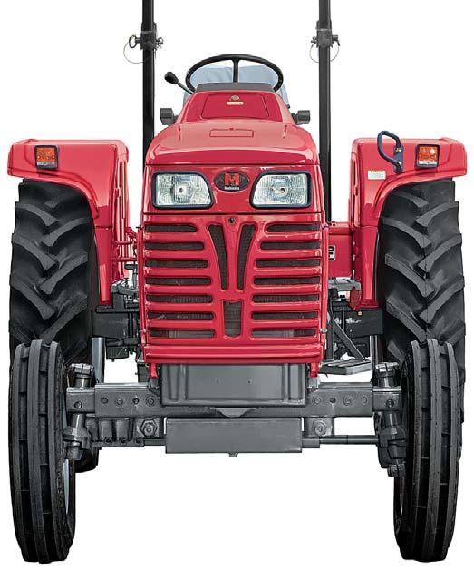
A.Turn Signal & Parking Lamp - R.H.
B.Head Lamp R.H.
C.Turn Signal & Parking Lamp - L.H.
D.Head Lamp - L.H.
Rear View :
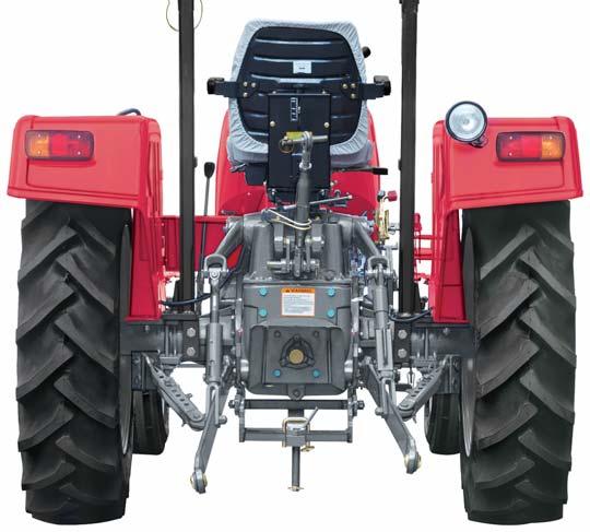
E.Turn Signal Lamp - L.H.
F.Position Lamp - L.H.
G.Brake Lamp - L.H.
H.Plow Lamp
I.Turn Signal Lamp R.H.
J.Position Lamp R.H.
K.Brake Lamp R.H.
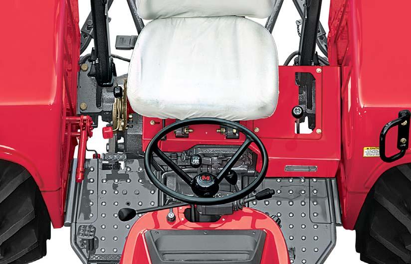
The following pages in this section detail the location and function of various instruments, switches and controls on your tractor. Even if you operate other tractors, you should read through this section of the manual and ensure that you are thoroughly familiar with the location and function of all the features of your new tractor.

Do not start the engine or attempt to drive or operate the tractor until you are fully accustomed to all the controls. It is too late to learn once the tractor is moving. If in doubt about any aspect of operation of the tractor consult your Mahindra USA Inc. Tractor Dealer.
This section explains briefly the operation of instruments, and controls. Full details wherever necessary will be found in forthcoming chapters at relevant operating sections.
The operator must be thoroughly acquainted with the location and use of all instruments and controls regardless of experience, must read this section carefully before attempting to operate the tractor.


The Instrument Cluster is a descriptive unit that gives the user various indications about the working of the tractor and its various features. It consists of the following.
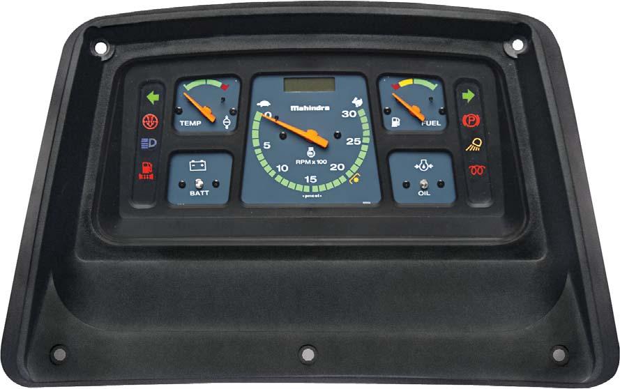
* This Indicator is not applicable on your Tractor Model.

RPM Meter
This meter gives the number of Revolution Per Minute of the engine. To arrive at the RPM value at any given point of time, multiply the pointer reading by 100.
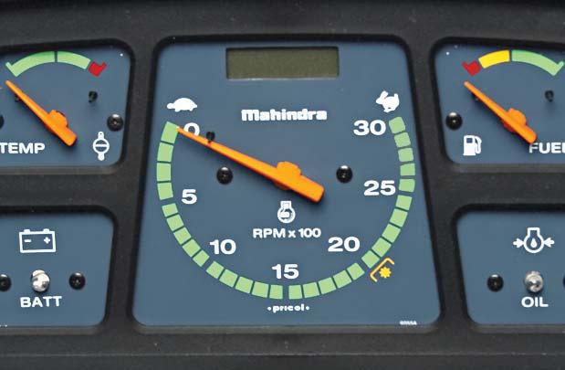
Example : If the reading shows 15, the actual engine RPM value = 15 x 100 = 1500.
PTO 540 rpm Mark
This Mark is located in the RPM meter. It indicates the Engine rpm at which the PTO shaft will rotate at 540 rpm.
Hour Counter
This is a Digital Hour counter located in the RPM meter. It is operated by pulses coming from alternator when the engine is running. Hour counter displays the cumulative engine running hours.
Fuel Gauge
The Fuel Gauge indicates quantity of fuel available in the fuel tank. The Indication is divided into three stages Viz. Red, Yellow and Green.
The Red Band starts at 2.90 US Gallon (11 lit)
Low Oil Pressure Indicator
This indicator will glow if engine lubricating oil pressure is less.
After putting ignition switch in "ON" position, the oil pressure indicator should be "ON". When the engine is running and healthy, it should be "OFF". If the indicator is "ON", the problem should be eliminated before starting the engine.
Engine Coolant Temperature Gauge
This gauge indicates coolant temperature of the engine. When the pointer lies in RED band :
1.Indicates excessive engine coolant temperature.
2.Get the cause identified.
3.Further engine operation should be done only after elimination of the problem.
Battery Charging Indicator
The indicator will glow if battery is not getting charged. Once the engine is running, this indicator should go OFF if the battery is getting charged. If the indicator glows continuously even when the engine is running above low idle rpm of engine, the cause should be investigated to prevent complete discharge of battery and possible damage of alternator.
High Beam Indicator
This indicator (C) glows when Head Lamps are operated in High Beam.
Parking Brake Indicator
This indicator (F) glows when either brakes or parking brake is applied.
Turn Signal Indicators
L.H and R.H turn signal indicators (A & E) are provided to indicate the direction of turning.
A blinking L.H turn signal indicator (A) implies that the L.H.Turn Signal of tractor is ON whereas a blinking R.H turn indicator (E) implies that the R.H.Turn Signal indicator of tractor is ON.
Heater Indicator
When the Key is turned to 2nd position, the Heater indicator (H) glows to indicate the activation of heater element provided in engine’s intake manifold. The Indicator continues to glow for 42 seconds. A timer controls this time.
1.Turn the Key to “ON” position and hold it till the heater indicator is put-off.
2.Crank the engine when the heater indicator light is put-off after approx. 42 seconds.
Plow Lamp Indicator
This indicator (G) glows when the Plow lamp is ON.
Air Filter Clog Indicator

This indicator (B) is ON when Air filter requires cleaning.
Water Level Indicator
This indicator (D) should be "ON" for 2 seconds when ignition switch is turned to 2nd position. This indicator will remain "ON" if the water level in the fuel filter needs to be drained. The indicator will go "OFF" after draining water from the fuel filter.
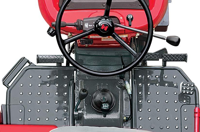
Switches
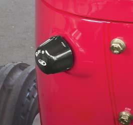

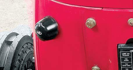
Rotary Light Switch
This is 3-Way rotary switch located on LH side of Scuttle. It operates in clockwise direction and the positions give operations as follows:
1 st–OFF
2 nd–Parking Lamp & Instrument Cluster Illumination
3 rd–High Beam, Parking Lamp, Instrument Cluster illumination
Combination Switch

This switch is located on LH side of Steering column. The lever operates in Five positions as follows.
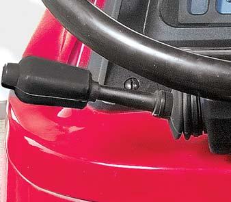
1.Towards the operator
Operates L.H.Turn signal in both up and down position
2.Away from the operator
Operates R.H.Turn signal in both up and down position
3.Upwards from Centre

Low Beam of Head Lamp with light switch in 3rd position
4.Downwards from Centre
High Beam of Head Lamp with light switch in 3rd position
5.Centre
Turn Off Turn Signal.
Horn Button
Press the Button (A) to blow horn.
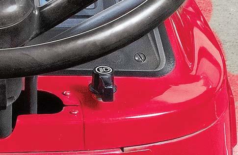
Plow Lamp Rotary Switch
This rotary switch when turned clockwise operates plow lamp.
Key
The Key operates the Key Switch.
Key Switch
This switch operates in three positions & carries out the following functions :
1.Off : The Engine and all electrical functions are Put-Off
2.Moving the key in clockwise direction brings electrical system to ‘On’ position to excite the charging circuit and activate the lighting circuit & other instruments.

3.Further movement of key against spring force energizes starter motor to crank the engine. The key should be released as soon as the engine fires. The Key springs back to its 2nd position.
Stopping the engine
Movement of the key in the anti-clockwise direction to the 1st position will discontinue the fuel supply to the engine thereby stopping the engine.
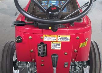
Hazard Switch
This is a Piano type switch and is located on the rear-scuttle in front of Operator’s Seat.
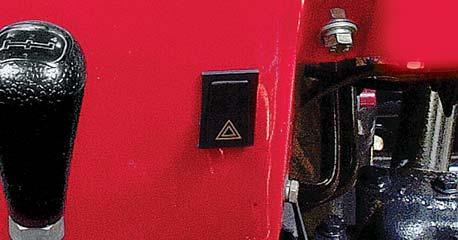
Operation of this switch will activate All the turn Signal Lamps.
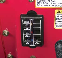
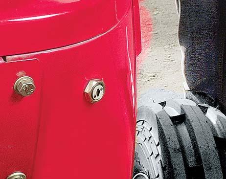
Fuse Box
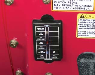
The fuses protecting the circuits are mounted in a fuse Box. A blown fuse can be confirmed by examination of the fuse. If it has blown, the separate ends of the wire will be visible inside the glass housing.
A separate fuse is provided for Rotary pump starting solenoid. The blown fuse will not let the tractor to start. Before replacing a blown fuse, inspect the wiring of the circuit for evidence of short circuit or any other fault which may have caused the fuse to blow. If no fault can be detected and another fuse blows, have the equipment examined by your Mahindra tractor Dealer.