FUEL SYSTEM
VI
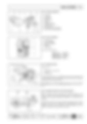
FUEL SYSTEM SCHEMATIC 1 2 3 4 5 6 7 8 9 10
Fuel Tank Fuel Filter Supply Hose Fuel Pump Injector Injection Pump Fuel Rail Grommet Return Hose Fuel Tank Fill Cap (Vented) Fuel Shut-off Valve (Electric)
FUEL FILTER ASSEMBLY 1 2 3 4 5
Air Bleed Plug Filter Head(Base) Spin-on Fuel Filter Gasket Filter Media
Fuel Filter Specifications: Media Type Filtration Area Filtration Level Max. Pressure
PF 905 2400 cm3 2-3µm 4 bar
FUEL TRANSFER PUMP Components: 1 2 3
Fuel Transfer Pump Assembly Push Rod Sealing O-Ring
The fuel transfer pump is a diaphragm type pump actuated by the camshaft driven push rod. Manual fuel system bleeding is facilitated by operating the pumping bail lever. Performance: At an engine speed of 3000 r/min, the fuel transfer pump delivers 60 l/h at a self-regulated pressure of 4.5 / 5.5 m H2O. FUEL TRANSFER PUMP PUSH ROD PROTRUSION With the engine rotated to position the camshaft eccentric (1) as shown, resulting in the lowest possible push rod (2) position with respect to the cylinder head plain, dimension ‘A’ should be 0.961.48mm. If the proper clearance cannot be attained, measure the push rod (2) length. The push rod (2) should be 152.45-152.65mm in length. Replace the push rod as required. No other adjustments can be made to change fuel pump push rod protrusion.
COMPILER TECO/ATL
REG. CODE
MODEL N°
DATE OF ISSUE REVISION
1-5302-351
50563
04.90
04
DATE
15.11.99
ENDORSED
65

