6 minute read
Control and operation


Operating and control elements
SymbolDescription
Confirm service interval
Selectquantitylimitationrelatingtoattachments(eg.hammer)
Operating hours and device data
Status of hydraulic pumps and electrical inputs and outputs
Recorded and stored errors
Immobilizer (must be activated by LIEBHERR customer service using a service connector)
Tab. 3-1
Overview of menu options
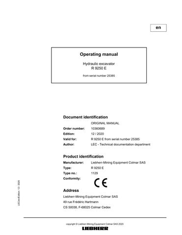
Reset daily operating hours counter menu
The daily operating hours counter can be reset to 0 using this menu.
Fig. 3-12
Resetting the daily operating hours counter
To set the daily operating hours counter to 0: Press the Up arrow key. The OK which is not crossed out will be displayed with a black background. Press the Menu* button. The operating hours will be reset to 0. ThearrowkeysymbolsUpandDownandtheMenusymbolwillnolongerbe displayed.
To exit the menu: Press the Back button. The submenu will be canceled.
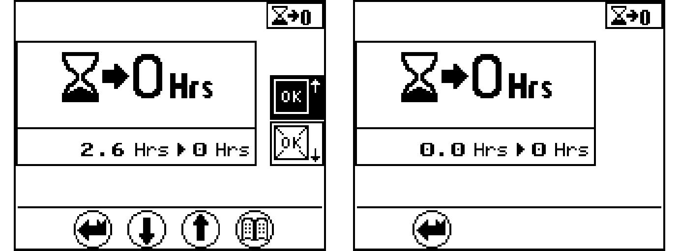
Confirm service interval menu
This menu is used for information on service intervals and to confirm service work which has been carried out.
Fig. 3-13 Service intervals menu
The operating hours of the next service inte
Apendingserviceintervalcanbeconfirmedamaximumof50operatinghoursbefore the service interval is due.
Whenthistimeperiodhas beenreached aquery willappear to ask whether the service work has been carried out.
Service work carried out.
Press the Up arrow key. The OK which is not crossed out will be displayed with a black background. Press the Menu button. Thecurrentoperatinghourwillbeconfirmedasthelastserviceintervalcarried out.
Service work not carried out. Press the Back button. The submenu will be canceled.
Allocation of quantity limitation options to external inputI1 menu
(Kit input; for example, activation of the hammer pedal)
Predefined quantity limitations have been assigned in this menu. The arrow opposite the symbol represents the current selection. In theexample(seeFig. 3-14),quantity 2 is activeif thespecified attachment is serviced.
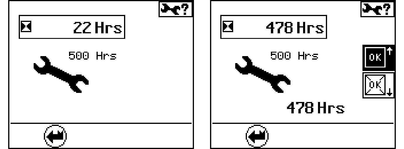
Fig. 3-14 Work equipment quantity limitation menu
Press the Up or Down arrow key. A different, predefinedquantity(1-4) canbeassigned (e g.when work equip- ment is changed).
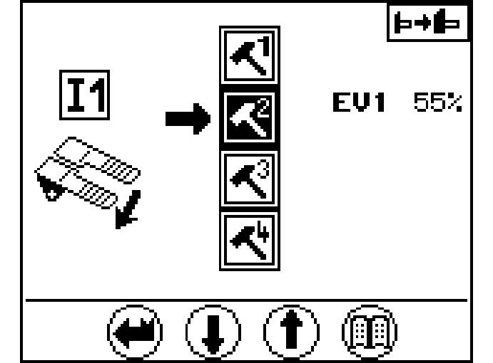
Press the Menu button. The selection is confirmed. The arrow displays the current selection.
To exit the menu: Press the Back button. The submenu will be canceled.
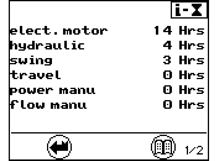
Operating hours menu
Page 1 provides an overview of the operating hours of individual units, processes and operating types.
Page 1 provides the service life in hours for:
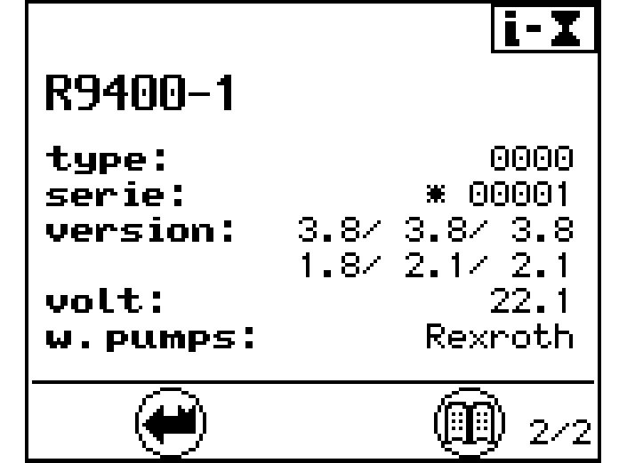
Press the Menu button again. Page 2 is displayed. The technical data menu, page 3, provides information on :
Press the Menu button again. Page 1 is displayed.
To exit the menu: Press the Back button. The submenu will be canceled.
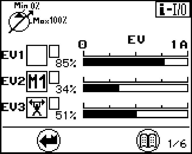
Status ofhydraulic pumps and electrical inputs and outputs menu
Press the Menu button again. Page 1 is displayed.
This screengives information about the operatingpositionofthehydraulic pumps.It gives the following indications for each working pumps :
If the flow limitation is activated for the pump. If it occurs, the symbol "R" is displayed in the field TI, see main screen. The screen 1/6 shows an example with theflowlimitationM1activated,whichlimitsthepumpP2to34%ofthemaximum flow.Shouldseveralflowlimitationsbeactuatedatthesametime,sotheonewith the smallest flow value has priority.
The graphic bar with electric current value indicates for the pump the amount of the momentary flow control signal.
Press the Menu button again. Page 2 is displayed.
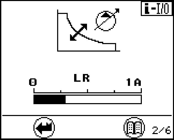
The present LR solenoid current (current value for power control) is showed on screen 2.
Press the Menu button again. Page 3 is displayed.
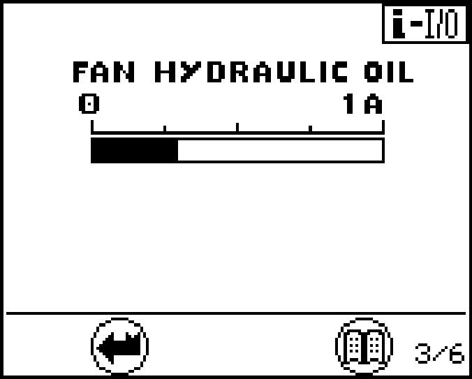
The screen 3 indicates for the fan pumps the amount of the momentary flow control signal.
Press the Menu button again. Page 4 is displayed. Press the Menu button again. Page 5 is displayed.
Press the Menu button again. Page 6 is displayed.
Pages 4, 5 and 6 provide an overview of the status of different electrical inputs. input has been deactivated.
The status of the inputs can be changed using the menu "set data" - "set E-code".
The screen 4indicates the status of the inputs for the different movements.
Thescreen5indicatesthestatusoftheflowlimitation.M1,M2,...correspondtomachinespecific(internal)oilflow limitations.I1,I2,...correspondtopredefinedoil flow limitations (see also menu "set option").
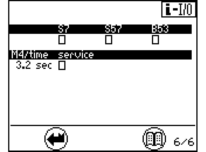
The screen 6 indicates the status other inputs. For the frequency inputs B53, the gnificant frequency is recognised by the system
B53 Swing motor sensor
S7 Safety lever servo control
S57 Swing brake
To exit the menu: Press the Back button. The submenu will be canceled.
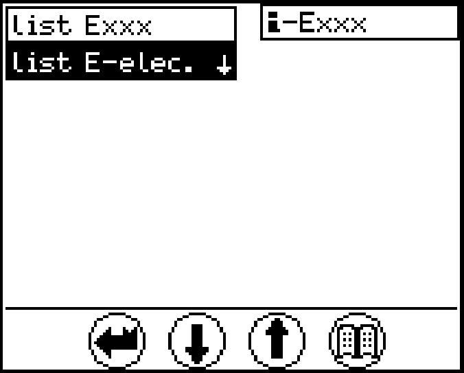
Error menu (operating errors and electrical system errors)
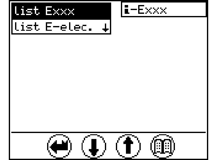
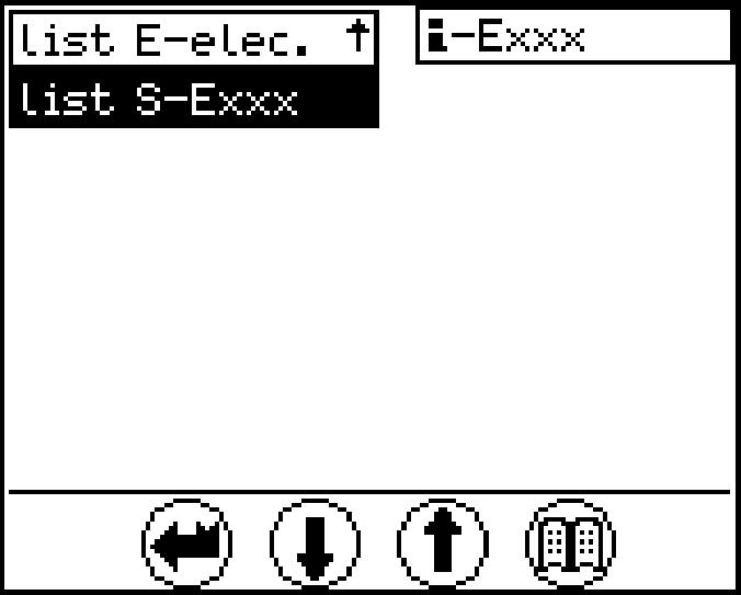
Fig. 3-21 Recorded errors menu
There are 3 selection options in this menu: list Exxx, machine errors recorded by the sensors are listed. list E-elec, all main screen cable errors stored when operating are listed. list S-Exxx, all errors which appeared when the service connector was connected are listed.
To select the desired error type: Press the Down or Up arrow key. The following or preceding error type will be displayed with a black background.
Press the Menu button. The submenu on a black background will be displayed. Ifmorethan6errorcodesarepresent,arrowkeyDownorUpcanbeusedto scroll to the next page.
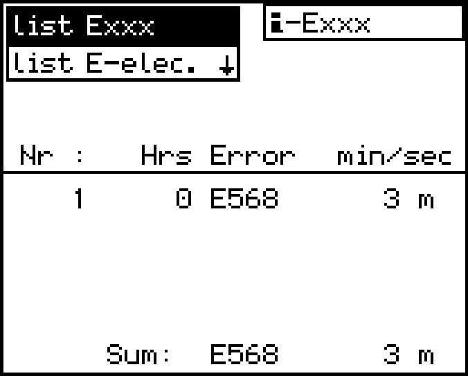
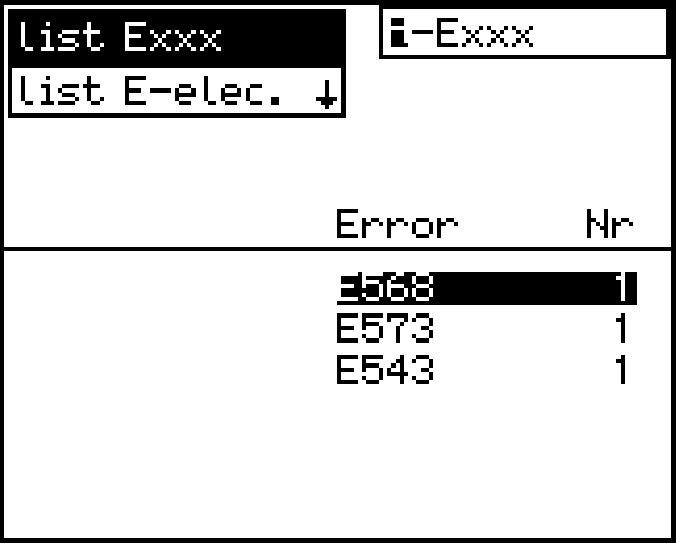
Machine error list Exxx:
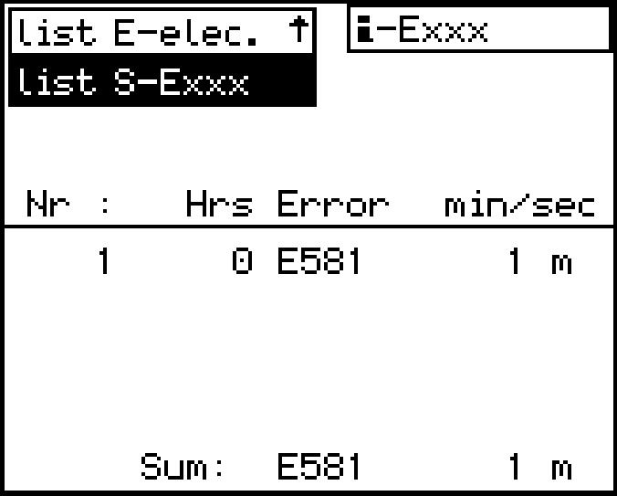
Fig. 3-22 Error list (Fig. left) and Error occurrence (Fig. right) menu
Select list Exxx s*: Error was indicated by a buzzer and was acknowledged using the Back button. The duration is given in seconds. m*: Error was indicated by a buzzer and was acknowledged using the Back button. The duration is given in minutes.
Press the Menu button.
The first page of the submenu appears.
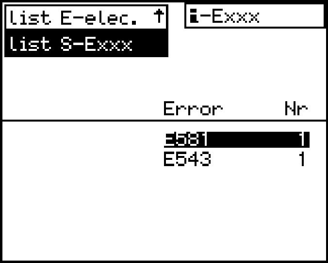
All errors and their error codes are listed on the first page.
Use the Down or Up arrow key to select the error code desired. Press the Menu button again.
The second page of the submenu appears.
Operatinghoursandthedurationofthefirstandlasttenoccurrencesoftheerrorselected will be listed on the second page.
Press the Back button.
The first page of the submenu appears.
PresstheBackbuttonagaintoselectanothererrortypeorpresstheDownorUp arrow key to select a new error code.
Note!
Only operating errors with an error code E 5xx will be displayed in the list Exxx menu.
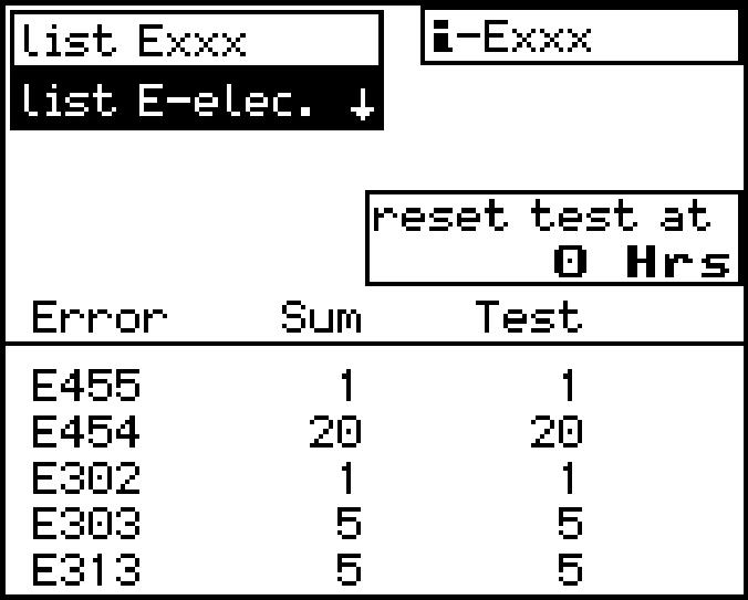
Cable error list E-elec.:
Occurrence of electrical error (Fig.
Select Cable error list E-elec.:
Press the Menu button. The submenu appears.
The column "Sum" shows the number of all errors that were ever noted.
Thecolumn"Test"showsthenumberoferrorsoccurredsincethelastdeletionofthis test error memory listing.
The operating hours above the test column show the operating hour when the last test memory was deleted (reset).
Press the Back button.
A different error type may be selected.
Other errors list S-Exxx:
Call up service operation error list menu
Selecting "list S-Exxx" also shows the errors according to the list in pages (refer to section "Warning symbols in the SY field", butthis time only theerrors that occurred during "service operation".
For each error, an overview can be shown and paged in just like for the "list-Exxx" selection. The column"Sum" shows the number of all errors that were ever noted.
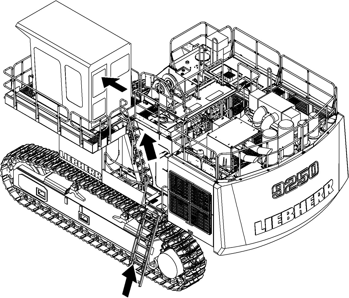
3.2The access and the outfit of the cab
Safely getting up b up or down onto the machine, as to upper structure should be positioned with the undercarriage in such a way that the steps and ladders are aligned with each other. two hands and one foot or two feet and one hand must always be in contact with the access system at the same time. fore you climb any higher. External influences, such as wind, can make it more difficult to open doors. Because of this, always use your hand for control when opening doors. Ensure that the door is latchedopen to prevent it slamming open and shut. icularly vigilant to realise the climbing and descent from the cab with the best safety conditions, and do or give the instructionstotheexecutionofpriorpreparations tobeaccomplished,asenunciated above, in order to displace yourself safely. still using the three-point support andsit downinthe and close it immediately using the door handle, before tilting down the safety lever, and start the machine. isnecessarytofastenyoursafetybelt. If unavailable, let it be installed before working with the door open. hethree-point support and closethe door as soon as you enter the cab. esafetybelt(ifavailable)beforetilting down the safety lever, and start the machine.
(grips)areingoodcondition.Inparticular, you should ensure that they are free of dirt, oil, ice and snow.
NOTE:Toensurethatthedoorsopenproperlyinallweatherconditions,thedoor seals must be dusted with talc or silicon at least every two months or more often if required. The door hinges and locks should be greased regularly.
Safely getting down
install yourself.
sitioned with the undercarriage in such a way that the steps and ladders are aligned with each other.
locking. Take care ofweatherconditions ! Unfasten the safety belt.
the machine when getting out and use three-point support, i.e. two hands and one foot or two feet and one hand must always be in contact with the access system at the same time. Climb down until youcanclosethedoorssafely.Alwaysuseyourhandforcontrolwhenclosingthe doors. Lock the door.
3.2.1Entering or leaving the cab Climbing up
Caution!
Entering or leaving the cab incorrectly could lead to injury. Proceedwiththesameattentiononexitorentryofthecab,aswhileclimbingthe machine
Ensure that the safety lever is always in its highest position when entering or leaving the cab.
Alwaysusethehandholdsprovidedforthepurposewhenenteringorleavingthe machine.
Facethemachinewhengettinginoroutandalwaysusethree-pointsupport,i.e. twohandsandonefootortwofeetandonehandmustalwaysbeincontactwith the access system at the same time.
Never use the control elements as handles.
Never jump from the machine.
Getting in
If the ladder is in its lowest position and the excavator is not running, you can climb up on the machine.
Climbinwiththeladdersandwithyourfacetowardstheladdersandusetheprovided handholds.