16 minute read
Control and operation


The access and the outfit of the cab
Lateral emergency exit
You can use the rear left window of the cab as an emergency exit.
To open the emergency exit:
If the rear left window has an emergency handle: Pull the emergency handle on the inside of the window. The window seal breaks into two parts and the window is released. Push the window out.
If the rear left window does not have an emergency handle: Breakthewindowwiththeemergencyhammerwhichisinstalledbetweenthetwo left windows of the cab.
3.2.7Interior lightings
The interior lightings are switched on using the switch S41 on the Keypad. Press the switch S41 The lights E7 are switched on. Press the switch S41 again. Interior lighting E7 are switched off.
3.2.8Fire extinguisher
Theinterior of the cab is fittedwithfixingpoints allowing themounting of afireextinguisher. These fixing points are on the right side wall of the cab, on the frame between the two windows.
Note!
It is the responsibility of the owner of the machine to decide if it must be fittedwith afire extinguisher or not, considering the operating conditions and the regulations which apply in the country and at the point of use of the machine.
Caution!
If yourmachine is fitted with a fire extinguisher: Always comply with the operating guide on the body of the extinguisher, Make sure, all the inspections of the fire extinguisher which are prescribed by the regulations applicable to the operating place of the machine are accomplished.
3.2.9Windscreen wiper
Windscreen wiper
When the ignition is switched on, pressing switch S14 will activate the windscreen wiper.
Press switch. Intermittent switching LED I in the switch illuminates.
Press switch again. Continuous operation. LED C in the switch illuminates. LED I in the switch goes out.
Press switch again.
Windscreen wiper is switched off. LED C in the switch goes out.
Setting the interval time for the intermittent switching
The interval time can be set when the ignition is on by pressing switch S14.
Pressthe switch until the windscreen wiper is switchedoff (LED I in switchgoes out)
Press and hold switch. LED I in the switch flashes.
Release the switch when the desired interval time has been reached. The interval time can be set to between 2 and 10 seconds.
Windshield washer installation
When the ignition is switched on, pressing button S11 will activate the electric windscreen washer installation.
Press and hold button. Washingwaterwillbesprayedontothewindscreenthroughtheoutletnozzles. The windshield washer runs continuously.
Release the button.
Washing water will be stopped. Windshield washer will run continuously for approx. another 3 seconds.
Windscreen washing fluid container
Fig. 3-43 Windscreen washing fluid container
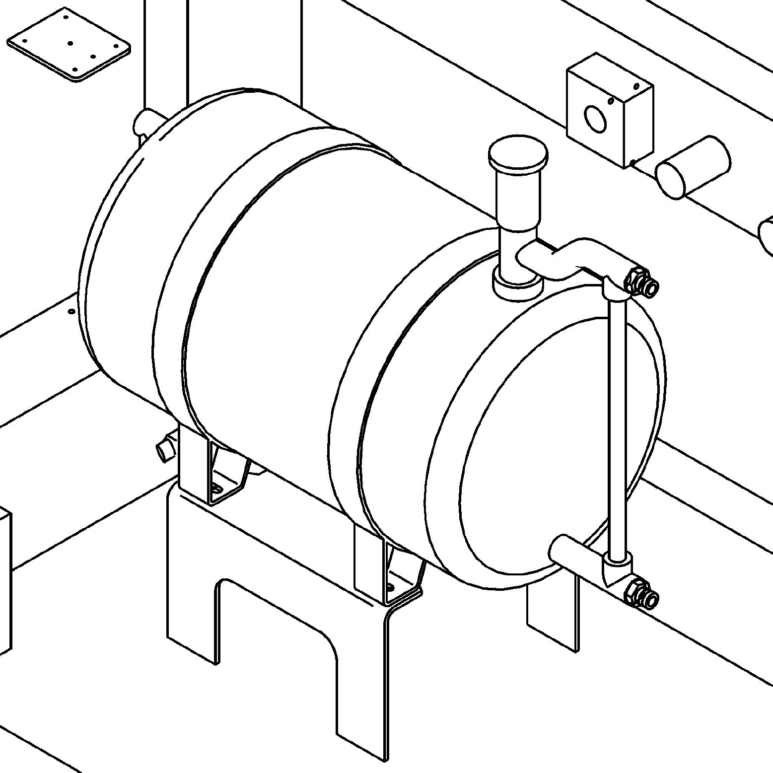
The containerfor the windscreen washing fluid is located under the cabin in thecab elevation.
The container can be refilled via the service trap with ordinary windscreen washing fluid.
Volume: see lubricant chart
3.2.10Field
Regularly check mirrors and cameras for condition. If necessary: ce to get access to them.

Regularly check mirrors and cameras for correct adjustment. For maintenance intervals, refer to the control and maintenance chart. Replace damaged mirrors and cameras immediately.
To cover the correct area: Set the cameras and adjust the outside mirrors soas to be able to see a person standingoutofthehatchedareadefinedbythefourcheckpointsgivenonthefigure above.
3.2.11Lighting
Regularly check lighting devices for condition. If necessary: ce to get access to them. For maintenance intervals, refer to the control and maintenance chart.
E1_1 Fuel tank floodlight
E1_2 Fuel tank floodlight (option, not represented)
E1_3 Fuel tank floodlight
E1_4 Fuel tank floodlight (option, not represented)
E2_1 Equipment floodlight
E2_2 Equipment floodlight
E3_1 Equipment floodlight
E3_2 Equipment floodlight
E4_1 Equipment floodlight (option, not represented)
E4_2 Equipment floodlight (option, not represented)
E5_1 Equipment floodlight (option, not represented)
E5_2 Equipment floodlight (option, not represented)
E6_1 Cabin catwalk floodlight
E6_2 Cabin catwalk floodlight (option, not represented)
E6_3 Cabin catwalk floodlight
E6_4 Cabin catwalk floodlight (option, not represented)
E8_1 Under uppercarriage floodlight (option, not represented)
E8_2 Under uppercarriage floodlight (option, not represented)
E18_1Counterweight floodlight (option)
E18_2Counterweight floodlight (option)
E21 Top of cabin floodlight
E23_1Counterweight floodlight (option)
E23_2Counterweight floodlight (option)
E58_1Top of cabin floodlight
E58_2Top of cabin floodlight
E59 Top of cabin floodlight
Equipment lights, fuel tank lights, catwalk lights and top of cabin lights
The fuel tank lights (E1_1, E1_2, E1_3 and E1_4), the catwalk lights (E6_1, E6_2, E6_3andE6_4)andthetopofcabinlights(E58_1andE58_2)arethedrivinglights.
The driving lights and the equipment headlights (E2_1, E2_2, E3_1, E3_2, E4_1, E4_2, E5_1 and E5_2) are switched on by pressing switch S10.
Press the switch.
Driving lights are activated.
LED 1 in the switch illuminates.
Press switch again.
Driving light are deactivated.
LED 1 in the switch goes out.
Equipment headlights are activated.
LED 2 in the switch illuminates.
Press switch again.
Driving lights and equipment headlights are switched on. LEDs1 and 2 in the switch illuminate.
Press switch again.
Driving lights and equipment headlights are switched off. LEDs1 and 2 in the switch go out.
Counterweight headlights and under uppercarriage lights (optional extra)
E8_1 and E8_2 are the under uppercarriage lights, and E18_1, E18_2, E23_1 and E23_2 are the counterweight headlights.
Pressing switch S22 when the ignition is on switches on the Counterweight headlights and the under uppercarriage lights.
Press the switch.
Counterweightheadlightsandtheunderuppercarriagelightsareswitchedon. LED in switch illuminates.
Press switch again.
Counterweightheadlightsandtheunderuppercarriagelightsareswitchedoff. LED in the switch goes out.
3.2.12Heating and air-conditioning system
Themachinehas astandardheating and air-conditioningsystem andcan also have an optional second air-conditioning system
Refer to the section "Heating and air-conditioning system" in chapter 5 for the configurations of the system.
Control unit front panel
Depending on the machines, two types of control unit can be installed:

S1 Rotary switch / necessary airflow
S2 Rotary switch / necessary air temperature
Cab airflow

The access and the outfit of the cab
The heater and the air conditioner can beused at the same time and independently for the airflow of the cab.
Make the airflow through the heater
Push fully the lever 1 forward. The water supply is closed.
Push button S12 to select necessary airflow. Thenewairentersintothecabthroughopeningsonthestepsandthroughthe vents on the left and right front.

Movethelever2toadjustthequantityofnewair/recirculatedaircomingintothe cab.
If lever 2 is pushed forward, the fan recirculates the air in the cab.
Make the airflow through the potentiometric control unit
The airflow in the cab is done through the evaporator in the cab roof.
Turn the air conditioner to off through button S2
Turn the blower fans to on.
Set thenecessary airflowthroughtherotary switch S1 and thevents oftheevaporator.
Heater operating instructions
Move the lever 1: The quantity of water running through the heat exchanger can be adjusted. If the regulator is fully pushed to the rear, the maximum quantity of coolant flows tothe heater.
SetthenecessaryairflowthroughbuttonS12andstarttheheaterunitthroughthe push-button S205 located on the right control panel.
Move the lever 2: The quantity of new air recirculated and entering the cab is adjusted.
Note!
The best heating effect can be got when the air is recirculated, which means the lever 2 must be fully pushed forward. In this position, a small quantity of external airis mixed with the recirculating air in the cab.
To quickly defrost the windshield:
Point the warm airflow through the vents to the front. Fully push the sliding regulator 3 to the rear. The maximum airflow is blown through the vents in the step onto the windshield.
When the lever 3 is fully pushed forward, part of the warm airflow is blown against the left side window.
Air conditioning operating instructions
To adjust the air conditioner fan: The electric motor is running. Use button S1
To turn on the air conditioning compressor and the condenser fan: The airconditioning can only be turned on if the evaporator fan unit is turned on through button S1 Use button S2
To set the necessary airflow: Use the rotary switch S1
To set the necessary air temperature: Use the rotary switch S2
To adjust the direction of the cold airflow: Use the vents on the evaporator unit.

To operate the air conditioning during the summer time: Fully push the lever forward. Turn the heater blower to off through button S12
To dehumidify the air in the cab: This procedure must be performed in case of very high humidity inside the cab during the colder season.
The air conditioning can be operated for ashort time at the same time with the heater in orderto remove the unwanted humidity and the condensation.
Forbestefficiency,setahighevaporatorairflowthroughtherotaryswitchS1and operate the heater with recirculated air.
Push-button
Frontpanel
7
Note!
If the controlunitrecognizes a system error in the heating / air conditioningcircuit, a flashing error code number F0-F5 is displayed. Refer to the section "Error code charts" further in this manual.
Operating
Switching on the control unit
Press button 4.
Thecontrolunitrunsaself-testforapproximately5seconds(softwareversion and equipment function are displayed on field 17). Then the operating hours are displayed on field 17. And then the last stored temperature adjustment is indicated on field 17. Bydefault,controlunitisinautomaticmodeandsymbol12appearsondisplay 19.
Temperature setting
Press button 2 to increase the temperature. Press button 3 to decrease the temperature.
The selected temperature is displayed on field 17. The new set value is stored 5 seconds after last button pressure.
Switching ON/OFF the air conditioning unit
Press button 1.
Air conditioning mode is operated. Symbol 11 appears on display 19.
Press button 1 again.
Air conditioning mode is deactivated. Symbol 11 disappears from display 19.
Note!
In caseof high outside temperature, and especially if the cab has been heated up by thesun, decreasethetemperatureinsidethecabas faras possiblebeforeturning on the air conditioner.
Open the windows for a few minutes and adjust blower speed to maximum speed via buttons 5 and 2.
Switching ON/OFF the reheat mode
In order to achieve a quick dehumification of the cab when setting the machine into operation, it may be advisable to briefly turn on the air conditioning operation when the heateris already operative.
Press button 6.
Reheat mode is operated. Symbol 10 appears on display 19. Theblowerspeedisraisedto100%.Ifnecessarythecontrolunitswitchesthe heating on, to hold ambient temperature at the desired value.
Press button 6 again.
Reheat mode is deactivated.
Symbol 10 disappears from display 19.
Note!
Toavoidoverloadingthebatteries,turnontheairconditioningmodeandthereheat mode only after the diesel engine is running.
Reheat mode is automatically limited on 10 minutes.
Ifthemachine isusedfor alongerperiod oftimewithoutusingtheairconditioner,pressthereheatbutton6aboutevery2weekssototurnonthecompressor.
Setting the evaporator blower speed manually
Press button 5.
Blower speed manual setting is operated. Indication bar13appears ondisplay 19andgivescurrentlyset blowerspeed. Automatic mode symbol 12 disappears from display 19.
Manual blower mode symbol 14 flashes on display 19 for 5 seconds.
Duringthese5seconds,evaporatorblowerspeedcanbeincreasedwithbutton2 or decreased with button 3 in steps of 10%.
Press button 5 twice. Manual mode is deactivated.
Symbols 13 and 14 disappear from display 19. Automatic mode is operated again. Symbol 12 reappear on display 19.
Switching ON/OFF the heating mode
Press button 7.
Heating mode is operated. Symbol 15 appears on display 19.
Press button 7 again.
Heating mode is deactivated. Symbol 15 disappear from display 19.
Switching the temperature unit from °Celcius to °Fahrenheit
Press and hold button 8.
Press button 3 additionally.
Temperature unit indication 18 switches over into °Fahrenheit.
Repeat same procedure to switch backtemperature unit indication to °Celcius.
Second air-conditioning (optional equipment)
At the machine start, the automatic second air-conditioning is activated by default. The two air-conditioning units are working alternately every 6 hours.
Press "Dual air-conditioning" button S26 on control board.
Automatic air-conditioning mode is deactivated.
First air-conditioning unit is activated.
Second air-conditioning unit is deactivated.
Press button again.
First air-conditioning unit is deactivated.
Second air-conditioning unit is activated.
Press button again.
Automatic air-conditioning mode is reactivated.
3.3Setting the machine into operation
Bringing the machine safely into service it. an authorized person, is in the work and movement area of the machine. vers areclosed,but that locks areunlocked, tofacilitate the fight against fire in caseof. against unintended movement. vicinity of the machine that it is about to start by sounding the horn.
Adjusting the operator’s standing position controls in such a way that you are able to work comfortably and safely. must be set to the insulation position throughout operation.
Protection from vibration - seat adjusting be adjusted depending on the weight and height of the operator. justmentmechanismsregularlyandensure that these seat characteristics remain as per th structions.
Utilisation in confined spaces
-operatedheaters inadequately ventilated spaces. Before starting in closed areas, ensure adequate ventilation. Follow the regulations which apply for the particular area of use.
Starting the machine safely
dinstrumentsforcorrectfunction,place l and tilt the safety lever up.
regulations given in the operating instructions.
st all display and checking devices. to run when there is adequate ventilation.Ifnecessary,opendoorsandwindowstoensuresufficientfreshairsupplies. make the control unit react sluggishly.
is operating correctly.
ea and then check the function of the travelandswinggearbrakes,thesteeringandthesignallingandlightingdevices. Lighting devices must always be clean.
Stopping the machine safely
it from rolling away.
ispossible,aligntheuppercarriagewith the undercarriage so that the sprockets locate at the back-end. This is the only one position which enables a secured access to every maintenance locationson the uppercarriage.
able. brakes.
erating instructions and tilt the safety lever up before leaving the cab.
compartments, remove every keys and secure the machine against unpermitted use and vandalism.
3.3.1Start / stop the machine
General information
Note!
Whenusingthemachineataspecificheightabovesealevelandinconnectionwith certainoutsidetemperatures,theperformanceandservicelifeoftheelectricmotor is decisively affected. Under theseconditions,thereis alsoan increasedriskofhydraulicoil overheating.
Before initial start up
Check the insulation resistance
Beforeinitial start up and after a long periodof non-use, andbeforethe excavator is connected to the power supply, check the insulation resistance:
The resistance values must never be less than the minimum authorised resistances given in the instruction manual of the electric motor.
If insulation resistances are less than the minimum authorised value: Refer to the procedure in the instruction manual of the electric motor.
Check direction of rotation of electric motor
Beforeinitialoperation,orbeforerestartingtheelectricmotorafterrepairstotheelectrical system, check the direction of rotation of the electric motor. Briefly start and stop the motor, and compare the direction of rotation to the arrows marked on the motor.
Activities before starting
Caution!
It is only possible to extinguish a source of fire when this one is accessible. Before starting, unlock all locks on the panelling of the hydraulic excavator. In the event of fire, the doors can be opened immediately and the fire extinguished.
Arrangement of locks: refer to chapter Maintenance.

Caution!
The activities below involve scald or burn hazards due to the high temperature of the hydraulic oil when the machine is at operating temperature. Read the Maintenance chapter in order to get informations about carrying out these activities.
Before starting the machine, the following activities should be carried out on a daily basis: ing air intake.
Turn on the electrical system
0 Off
1 Contact position

2 Not used P Park position
3 Start position
Turn on the high voltage circuit
Close the battery switch S9_1.
Makesurethattheexcavatorisconnectedtoandsuppliedwithelectricpowerby the power station or the field switch.
Turn ignition key S1 to contact position.

Push button «Control ON» S183 on control board.
The high voltage circuit operates. H183 in S183 button comes on.
The display and the control unit run through a self test.
Make sure all indicators function properly after turning the electrical system on, i.e. thelight emitting diodes (indicator lights and gauges) turn on for ashort time thenthecompletefieldoftheLCDindicator200turnsmomentarilyblack(thematrix indicator is energised completely for a short time).
Note!
If no automatic check of the keyboard and monitoringscreen is carried out when the ignition key is in the contact position, check that the main battery switch is set to on.
Turn on the low voltage circuit
The high voltage circuit is on.
For machine with option «Vessel - excavator data link», make sure that button «External supply 440V» S186 is on position «0».
Push button «Control 440V ON» or «Control 400V ON» S207 on control board. The low voltage circuit operates. The 24V control circuit operates. H120 in S207 button comes on.
Turn on the external 440V supply formachine with option «Vessel - excavator data link»
Make sure that the high voltage circuit is off.
Close the battery switch S9_1
Makesurethattheexcavatorisconnectedtoandsuppliedwithelectricpowerby the power station or the field switch.
Turn ignition key S1 to contact position.
Turn button «External supply 440V» S186 to position «1» on control board. The low voltage circuitof theexcavatoris supplied with440V coming directly from the vessel.
Service interval display

Fig. 3-61 Service interval request
After the automatic check, any service interval that may be due will be indicated by a graphic symbol.
In place of the operating hours information, the number of hours relating to the service interval required will now be displayed.
The service interval request will go out after approx. 8seconds.
Start the electric motor
Control board
Depending on the machine, the start procedure of the electric motor is different.
Standard start procedure
Make sure that the high and low electrical circuits have been turned on as described above.
Push button «Motor ON» S181 on control board. The motor starts. H112 in S181 button comes on.
Caution!
Inordertopreventtheelectricmotorfromoverheating,motorstartingattemptsare limited for a given time frame. You must observe a sufficient time interval between two consecutive starting attempts.
Whenthemotoriscold,donotrestartmorethan5times.Thenwaitabout1hour before restarting.
When the motor is already warm, we recommend that you do not restart more than3times,waitingabout10minutesbetweentwoconsecutivestartingprocedures.
Start procedure for option «Vessel - excavator data link»
Control board
Make sure that the high and low electrical circuits have been turned on as described above.
Push button «Motor ON» S181 on control board.
The excavator sends a start request to the vessel.
If indicator H176 «Start allowed» comes on:
The electric motor starts.
H112 in S181 button comes on.
The excavator sends the information «Motor ON» to the vessel.
If indicator H175 «Start not allowed» comes on:
It is not possible to start the electric motor.
Turn the high and low electrical circuits off.
If indicator H177 «Sequence in progress» comes on:
It is not possible to start the electric motor immediately.
Wait until the indicator H176 or H175 comes on.
Caution!
Inordertopreventtheelectricmotorfrom overheating,motorstartingattemptsare limited for a given time frame. You must observe a sufficient time interval between two consecutive starting attempts.
Whenthemotoriscold,donotrestartmorethan5times.Thenwaitabout1hour before restarting.
When the motor is already warm, we recommend to do not restart morethan 3 times, waiting about 10 minutes between two consecutive starting procedures.
Warm-up procedure for hydraulic circuit
If the excavator is started when the exterior temperature is below 0°C, the operator must do the warm-up procedure:
Make sure that the hydraulic oil temperature is sufficient (refer to lubricating sectioninchapter5)todothisprocedure.Ifthistemperatureisnot sufficientwhena preheating system is installed on the excavator, keep preheating.
Start the electric motor and let it run without load during the first 3 to 5 minutes and make sure that no error symbols are shown on the monitoring display (refer to the functions of the display in chapter 3).
Step 1 - Open louvers and tarpaulins (if installed).
Step 2 - Carefully activate the working hydraulic circuits. Do not reach end positions of piston rod. Operate all movements at reduced speed: and repeat 10 times before moving to next cylinders: 4 times in each direction.
Step 3 - Repeat step 2 a second time.
Step 4 - Repeat step 2, with reaching end position of piston rod.
Step 5 - Repeat step 4 a second time.
Step6-Checkoiltemperatureinhydraulictank.Ifoiltemperatureisunder10°C, repeatstep4untiloiltemperaturereaches10°C.Ifoiltemperatureisabove10°C, move to step 7.
The step 7 that follows is applicable only to crawler excavators.
Step 7 - Start the travel hydraulic circuits very slowly forward and backward on approximately 10 meters. Repeat 4 times.
The excavator can now be operated.
Notes after starting the motor
Run themotor until thehydraulicoilisatoperating temperature. Thecontrols operate sluggishly at low oil temperatures. Movethemachinecarefullyinanopenspacetotestthefunctionofthetraveland swing brakes.
Check that the attachment is operating perfectly.
Switching off the electric motor
Fig. 3-64 Electric motor and system switch off buttons

Push the button S182 "ENGINE OFF".
The electric motor is stopped. The indicator light in the button S181 goes off.
Switching off the control system 400 V
Push the button S208 "CONTROL OFF".
The indicator light in the button S207 goes off.
Switching off the control system 6 kV
Push the button S184 "CONTROL OFF".
The indicator light in the button S183 goes off.
3.3.2Starting aids (optional equipment)
Preheating of the hydraulic excavator
Thehydraulicexcavatorcanbepreheatedwithanexternalelectricpowersupply(80 kW, 400 V, 50 Hz).
The electric power supply must be connected to the excavator through a connector situated on the cab elevation. At this time and if the principal switch on the electric box U42_1 is activated, all preheating units are starting.
A light H103 on the control unit alert the operator that the preheating is activated. When the preheating is activated the excavator can be started but no movement is possible.
Preheating control
Connect thegenerator on the 200 A socket situated in the batteries room. Themotorstartingisavailableduringthepreheatingbutthemovementsfromtheexcavator are forbidden.
Hydraulic tank7 resistors from 2kW / 400V
Automatical control with internal thermostat : ON : 15°C / OFF : 27°C
Blower3 blowers from 3kW / 230V and 2 blowers from 1kW / 230V
Separate control with switches, automatical switch off at 50°C
Batteries4 heating covers from 100W / 230V
Automatical control with internal thermostat : ON : 18°C / OFF : 27°C
Splitterbox2 resistors from 500W / 230V
Control with an external temperature transmitter : OFF : 85°C
CabinHeating filaments 230V :
3 x 500W / 230V + 2kW / 230V
Separate control with switches and with an external temperature
Heating filaments 24V :
500W / 24V, emergency exit
Separate control with switches and with an external temperature
Cabin1 preheater from 3kW / 400V
Regulated with a thermostat
Greasing1 heating cover 0,8kW / 230V
Electrical boxesResistorsfrom 20Wand150W/24Vin the boxes from the excavator.
Hydraulic components1 preheater from 9kW / 400V
1 preheater for travel motors (preheater 1)
1 preheater for rotating motors (preheater 2)
2 preheaters for the pumps (preheaters 3 and 4)

Maintenance
Weekly, check and clean the blowers.
User’s procedure
Excavator is stopped
Preheating
Measures to be taken after motor stop or prior to motor start
(own thermostat) of hydraulic oil in the hydraulic tank and in the suction pipes. (own thermostat) of batteries (own thermostat) of splitterbox oil (heater, seat, windows, (...) boxes.of the greasing tank of all working pumps, slew pumps, fan pumps by thermostatically controlled preheater Nr 1
Usual standard procedure to park the excavatorNo need to connect the Gen-Set / to use the preheating kit ground so that a maximal quantity of oil is in the hydraulic tank : stick and bucket cylinders completely raised in, bucket on the ground (see Fig. 3-67 on page 67)excavator with an electric motormotor, no need to connect the Gen-Set as the high voltage supply is available the preheating functions in the electric box and verify that the white led "400 V" lights up manding the blowers are turned on and that the blowers run heaters are turned on and that the
Weather conditions and machine stop operationent air temperature will not be lower than -10°C during the downtime OR hour AND the ambient air temperature is lower than -10°C (daily maintenance The machine is turned off more than one hour AND the ambient air temperature is below -10°C
CaseWeather conditions and machine stop operation Measures to be taken after motor stop or prior to motor start
3The machine must start and has been turned off as described in case Nr. 1
Standard procedure to run the excavator
4The machine has been previously turned off as described in case Nr.2 preheatingintheelectricboxandverify that the white led "400 V" is off vator ments at reduced speed : it down very slowly, repeat these operations 5 times operations 5 times pass valves on the attachment and if the temperature is below -30°, use the valves on the attachment to by-pass thecylinders and alsotoheat up the oil in the pipes and the hoses on the attachment during the operation Nr. 5 as the by-pass valves are open, there is no movement of the attachment. pass valves.
3.3.3Emergency and safety operations Emergency
shut down
For emergency shutdown, you can: S1 to the «0» position.
S100-1, S100-2, S100-3, S100-4 (if in- copyright © Liebherr-Mining Equipment Colmar SAS 2020