11 minute read
Control and operation


Working with the machine
Note!
Increased wear.
Donotusethepositioningswingbrakepurelyasaservicebrake,butonlyasastop and parking brake.
Usingthisbraketostoptheuppercarriagerunningat thefull swingRPM isnot permissible since this would result in a quick abrasion of the brake discs.
In any case, first use thehydraulic brakingto greatly reduce thespeed of the uppercarriage
Depress the pedal 10 when the uppercarriage is near standstill
The uppercarriage canbestoppedprecisely and progressively in thedesired position.
3.4.2Working position
Work with the machine is generally to be carried out over the idler.
Note
Drive backwards when you are working lengthwise with the backhoe bucket.
3.4.3Joystick functions when setting up the machine
Operating the stick cylinder
The stick cylinder is operated using the left joystick 4
Push the joystick back a Stick will be drawn in.
Push the joystick forwards b Stick will be extended.
Operating the boom cylinder
The boom cylinder is operated using the right joystick 3
Push the joystick back h Equipment will be raised. Push the joystick forwards g Equipment will be lowered.

Operating the bucket
The bucket cylinder is operated using the right joystick 3.


Fig. 3-82 Operating the bucket cylinder


Push the joystick to the left e Bucket will be tilted inwards. Push the joystick to the right f Bucket will be tilted outwards.
Operating the bottom dump shovel bucket
Dependingonthemachines,theconfigurationoftheshovelflapcylinderscanbedifferent. You can have:
A Cylinders-up configuration
B Cylinders-down configuration
Thus:
A Cylinders-up configuration
B Cylinders-down configuration
E1005 Cab connection box
S232 Selection key
If installed, the selection key S232 is located in the cab connection box E1005. You can also referto chapter 4 of this manual.
Use the key S232 to select the cylinders configuration A or B that you have on your machine.
3-85 Operating the bottom dump shovel bucket
The bottom dump shovel bucket is moved via two pedals, 7a and 7b

Push pedal 7a. Shovel bucket will be opened. Push pedal 7b Shovel bucket will be closed.
Ifthedisplayshowsanerrorcodeortheshovel bucketmovementsarestoppedduring the operation:
Make sure that the configuration A or B which is selected is correct.
Floatpositionofboomcylinderforbucketoperation(optional equipment)
3-86 Float position
To turn on the float position for the lift cylinders, Move the right joystick 3 forward, Push the button S5 or S6 on top of the handle at the same time.
Now the bucket can be used for grabing work while moving the joystick 4 forward to extend the crowd cylinders.
copyright © Liebherr-Mining Equipment Colmar SAS 2020
Theattachmentcanthenmovefreelyupordowndependingongradeandthebucket will automatically follow the ground contour.
Combined movements
Movingajoystickdiagonallyresultsintheworkfunctionsconcernedbeingcombined. This allows different equipment movements to be activated at the same time.
The operator can do the following movements without any additional manipulations.

When the swing movement is actuated, all working functions / movements are possible without affecting the swing movement.
Duringtravel,everyattachment movementis possible,butthe swingmovementhas priority. In this case, the travel movement is reduced.
3.4.4Loweringtheworkequipmentwhenthemotorisnotrunning
In an emergency, the equipment can be lowered when the electric motor is not running.
Fig. 3-87 Lowering the equipment when the motor is not running

Turn the ignition key to contact position 1
Operate the joystick or the foot pedals until the equipment has lowered.
Note
Thisreserveislimitedandisonlysufficientforsmallmovementsofthepilotcontrol devices.
Only operate the joystick in the directions for lowering the equipment.
3.5General working methods
3.5.1Minimum impact working methods for your machine
Toincreasethe servicelife of themachine andavoidunnecessary damage andthe resulting repairs, please note the following points: stopping the equipment on the walls of the ditch. materialtoberemoved,inthelongitudinaldirectiontoo,isnotpermitted.Repeatedly hitting the work equipment against rock or other hard material will damage steel parts and machine components. ofboom,stickandworktool,theworktool couldhitor break through into the cab. This could operator. in rocky material. This will extend the work cycles and could result in damage to the bucket and other machine components. l partner if special teeth are required for heavy or special applications. thisshouldoccur,slowlylowerthemachine to the ground. Do not permit the machine to lower quickly and do not intercept thefalling movement using the hydraulics,sincethis could result indamage to the machine.
3.5.2Preparatory activities
Danger!
Risk of fatal injury and damage to the machine when working.
erating instructions.
Position the machine so that the load material can be taken up above the idler.
Danger!
Insufficient support and machine damage.
Danger!
Risk of fatal injury due to rotating the machine. Ensure that nobody stands within the hazard area r of the machine.

Caution!
Risk of injury when working. Always wear safety shoes and, particularly when leaving the cab when demolition work is going on, a protective helmet and safety glasses. Always wear the seat belt. Use the horn to give a short warning signal before starting work.
3.5.3Positioning of the machine
Settingupproperlyisapre-requisitetosafeefficientloading,andhelpsmaintainstability,power andbenchlevels.It will alsoreduceoperator fatigue.Positionthe excavator as close to the working face as safety permits.
Caution!
Always ensure there is sufficient clearance between the counterweight and the face, including allowing for any rocks or material that may fall down.
The recommended digging range is about a 90° arc in front of the machine (A).


Note!
Avoid digging at right angles to the tracks.
3.5.4Working with thebackhoe bucket
Danger!
Risk of fatal injury and damage to the machine when moving the backhoe bucket. Ensure that the backhoe bucket is not slewed too close to the cab. tor.
Ensure that nobody is standing within the hazard area of the backhoe bucket.
Digging
Aligntheshovelarminsuchawaythatitsundersideisatanangleofapprox.30° forward to the vertical.
Align the backhoe bucket in such a way that its underside can enter the ground at an angle with the axle of the shovel arm between 10° and 20°.


3-93 Taking up grab material
To lift out the grab material, slowly and evenly slew in the shovel arm.
3-94 45° backward to the vertical
Assoonastheshovelarmisatanangleofapprox.45° backwardtothevertical, raisetheboomslowlyandevenlyinadditiontoslewingintheshovelarmandthe backhoe bucket. Stopping suddenly will result in impact loads and vibrations. When the backhoe bucket is full or the shovel arm can no longer be slewed in, raise the boom and backhoe bucket until the filled surface is parallel to the ground.
Note!
Foraefficientdigging,thedepthofthe of the shovel arm.
Loading the transport vehicle
Danger!
Risk of fatal injury due to falling grab material.
Do not load the transport vehicle so high that the grab material could drop out over the walls of the vehicle.
Ensure that nobody is standing in the danger.
Load anoccupied truck only if all safety requirementsarefulfilled, notably inorder to protect the truck operator.
3-95 Emptying grab material
If possible, the machine should stand higher than the transport vehicle to avoid having to lift the grab material unnecessarily.
Stopthetransportvehicleinapositionthatallowsittobeloadedfromtherearor the side.
Slew the machine's equipment above the loading area of the transport vehicle. Distribute the grab material evenly over the loading area of thetransport vehicle by slewing the backhoe bucket and shovel arm out, slewing the upper carriage and possibly also moving the boom.

Ifthebackhoebucketisnotsufficientlyemptiedorthereisstillgrabmaterialinthe backhoe bucket, slew thebackhoebucketin andout several times to loosenthe grab material.
3.5.5Working with the Shovel bucket Digging
Tomaximisemachinepowerandbreakout,maintaingradeandfillthebucket,correct digging angles and technique should be used.
3-96 Digging
Mostdiggingshouldbestartedwiththebucketalmostfullycrowdedback(50mm off stops or end of cylinders).
When cleaning up or digging at floor level, angle the teeth aggressively to break out any toe that may be encountered.
Keepingtheheel ofthebucketoffthegroundthereforecreatingavoidunderthe rear of the bucket.
Operate with the teeth and bucket lip doing all the work.
Note!
Avoiddigging at right angles to the tracks.
Caution!
Eachtimethe stick is crowded back tocommencea cut, extreme caution must be taken not to hit the tracks.
The clam must always be closed when di Avoid working on the cylinder limits and bucket stops during the digging cycle. Continual use of these practises will lead to premature failure of seals and Orings andcan causestress fractures totheclam, stickand bucket and damage to the boom and superstructure.

Crowd the bucket in (down) while closing the clam. This practise makes use of gravity to help minimise shock loading on the bucket cylinders.
Neverdig,orattempttobringdownanymaterialoverhang,withthebucketwhile the clam is open or partly open.
Do not attempt to dig or clean the floor or face with the clam open. These practises can cause considerable damage to the clam cylinders.
Unload the bucket
Fig. 3-97 Unloading of the bucket
Whendumpingtheload,tipthebucketforwardslightlyastheclamopens.Thishelps direct the material to fall centrally into the tray and avoids spillage.
Thepositionofthebucket backboardwhentheclam opens,directlyaffectstheposition of the load in the tray.
Bucket in ideal position resulting in material falling straight down. Loading centre of the haul truck.
Attaching and removing attachment parts safely

have general approval from Liebherr for installation or attachment may not be installed or attached to the machine wit sary for this purpose. chine on level, firm ground. not safely positioned on the ground or supported with appropriate supports. s,youmuststoretheequipment,switch off the engine and press the start key to the contact position and both joysticks draulic system. and which have sufficient load carrying capacity. es not have sufficient load carrying capacity. Wear work gloves when working with wire cables. tiltedup.Neveruseyourfingerstolocatebores;usethecorrectpunchfortheprocedure. all bolts and connections are tight. the hydraulic circuit to stop dirt entering. Only allow authorized persons in the vi- cinity of the machine or the lifting device used.
Removing and installing attachment pinssafely hole conductor held by another person must be used. the bolt's threaded hole and only hammer these screws. meansofcastlenutsandcotterpins,firstdrivethe bolt tothestop,thenscrewthecastlenutby handuntilcontactandthen onlypull it far enough to push in the cotter pin.
3.6Transport
3.6.1Travelling procedures for mining machine
Thelifeexpectancyofundercarriagecomponentsisbasedonstandardworkingconditions with a maximum travel ratio of 5% per service meter unit. Working and / or travelling on uneven ground and / or abrasive material will influence the lifetime of the components and attract additional cost for the undercarriage components.
Downhilloruphilltravelonaslopehasalsoaneffectonthelifeexpectancyofundercarriagecomponentsandontheirwearrate.Indeed,eveniftheslopeangleisbelow the maximum permitted travelling angle, the increase of the slope angle causes the increase of the force and of the contact pressures applied on all track components (trackpadassembly,sprocket,...).Onanindicativebasis,thetravelforceappliedon thetrackcomponentsismultipliedbytwofromaslopeangleof5°(8,7%)andismultiplied by 2,5 from a slope angle of 10° (17,6%).
In general travel action has to be kept to the lowest level that is possible. Minimize travelling with turning through a narrow turning circle and long distance travel.
To minimize the travel ratio, professional mine planning with longfront winning sectionsispreferred.Ifdiggingoperationsatvariousspotsarenecessary,apropershort termandlongtermplanofwinningoperationshastobeemployedtoguaranteelong term use of the excavator at one place before moving to another location.
However, if frequent machine movement is necessary, the following set of procedures defined by Liebherr to minimize possible machine damage, downtime and wear have to be taken into consideration.
General
In order to move themachineforwards: withthe excavator instandardforward position, depress travel pedals all the way forward with the toes. Direction of travel is in the direction of idlers.
Inordertomovethemachinebackwards:withtheexcavatorinstandardforwardposition, depress travel pedals all the way down with the heels. Direction of travel is in direction of the drive sprockets.
Moving the machine during loading operations
Moving the machine during loading operations means adjustment of excavator dig- ging and / or truck loading position of some meters.
Important procedures: cket and close up the attachment to a position as close as possible to the excavator undercarriage. onthegroundandliftingthemachine,then counter turning theundercarriage, isnot allowed, becauseit could causepremature structural damage to the machine. terialaroundthetrackswherethemachinewillnotturn, you mustmove the machine several meters forwards and/ or backwards and attempt to turn again. ator can use theswing function to assist inturningthetracks,i.e.ifturningtotheright,swingupperdecktotheleftandvice versa.
Walking themachine over distance
Fig. 3-98 Hazard area r

Walking the machine distances means any movement of the machine of more than 100 m or for a time period longer than 3 minutes, whatever comes first.
Inadditiontoabovementionedguidelines,whenmovingthemachineduringloading operations, the following procedures apply: cleanall very dirty parts oftheundercarriage and remove the unwanted materials. with a heat gun, to monitor the temperature of the drive components, including the track and carrier rollers.
Danger!
Duringthemovementofthemachine,thepersonwhichischeckingthetemperature of the different rollers must always be out of the hazard area r of the machine and t and in radio contact with him.
For the checking of the temperature, the excavator should stop moving. And only when the excavator is stopped, the person could go in the hazard area r to check the temperature of the different rollers.
The machinecould only start moving againwhen the driver has seen the operator out of the hazardarea r growing up about 20°C above ambient temperature, interrupt travel and only commence again after parts have sufficiently cooled. tospeedupcoolingprocedureitisad- visable to have a water truck standby, to hose the heating components during travelling or cooling break. venewithminesafetyregulations,swingwhilsttravellingtoequallyloadtrackrollers. However, always ensure that clear forward vision is maintained.
Travelling the machine down grades or upgrades
Inadditiontoabovementionedguidelines,whenmovingthemachineduringloading operations or when walking the machine distances, the following procedures apply: themachinedownwiththetrackmotorfirst,i.e.themachineismovedbackwards. thefinaldrivesmustbeattherearoftheexcavator. indicatedinthe"Technical data"section of this manual(machine mustbe able to walk up unaided). When moving down the ramp never allow the machine to fall downontheattachment. Whenwalkinguptherampneveruseattachmentto assist the movement by pushing with the hydraulic power of the bucket, stick or boom.
Travelling the machine first time
The slide bearing (friction bearing) of the track rollers needs some time for runningin.Ifthebearingbecomeshotatanearlystageof machinelife,thismaycauselubrication problems during further life. Therefore when travelling the machine the first time aside from all above mentioned guidelines it is strongly recommended to move carefully and at reduced speed.
Note!
Warrantymaybecomevoidiffailuretorecognizeandcomplywiththerecommended travel operating procedures, as outlined in this document, is noted.
Transporting the machine safely
ons, use only suitable means of transport and lifting devices with sufficient load-carrying capacity.
tion.
ontotheflatbedtrailershouldnotexceed an inclination of the angle value indicated in the "Technical data" section of this manual (machine must be able to walk up unaided) and should have a wooden cover to prevent sliding back.
i.e. before driving up the ramp, clean any snow, ice and mud from the crawler / wheels of the machine.
iving (crawler excavator) onto the travel pedals.
ing up onto the flatbed.
hold the attachment securely over the loading area, drive very carefully up the ramp and onto the transportation vehicle. restrictions during transport on hoe attachment, tilt the arm in and dismantle the bucket during transportation. trailer,theupperstructuremustbesecured facing the undercarriage using the stop bolts (only A devices). ing individual parts using chains and blocks to prevent slipping. ignition key and tilt up the safety lever. about the route to be travelled, particularly as they relate to width, height and weight restrictions. through tunnels. itwasloaded.Removeallchainsandblocks.Starttheengineaspertheoperating instructions.Drive carefully offthetraile the workingattachment as securely as possibleover the groundwhiledoingthis. Have a spotter guide you.
3.6.2Excavator lifting and lashing operations
Danger!
For safety reasons, always consider the precautions given in this section.
Lifting precautions
Lift element: spondingtransport drawing, s of other kind (cables, chains, slings) if necessary, nces in accordance with the regulations, gs shown on the assembly drawing, ement has been already dismounted, e corresponding transport drawing, always respecting the angles given on the sticker for lifting and lashing operations (refer to the description below).
Additional lifting precautions for backhoe buckets
When you lift the backhoe bucket, also obey theprecautions that follow: he center of gravity of the bucket. transport position as shown in the transport drawing.
6 m, turn over the bucket safely.
Additional lifting precautionsfor shovel buckets
When you lift the shovel bucket, also obey the precautions that follow: the stickers placed on the bucket.
Lashing precautions
Lash element: e center of gravity of the bucket. in order to ensure safe lashing, sponding transport drawing, respecting the angles given on the sticker for lifting and lashing operations (refer to the description below), supporting surface so as to avoid element to slip (e.g. using wooden parts, nonslip mats...), friction is guaranteed by manufacturer certificates, tween the load and the support, between the support and the flatbed trailer), carried are free of dirt, ice, snow, oil and grease.
Additional lashing precautions for backhoe buckets e center of gravity of the bucket. transport position as shown in the transport drawing.
When you lash the backhoe bucket, also obey the precautions that follow: the stickers placed on the bucket.
6 m, turn over the bucket safely.
Additional lashing precautions for shovel buckets e center of gravity of the bucket.
When you lash the shovel bucket, also obey the precautions that follow: the stickers placed on the bucket.
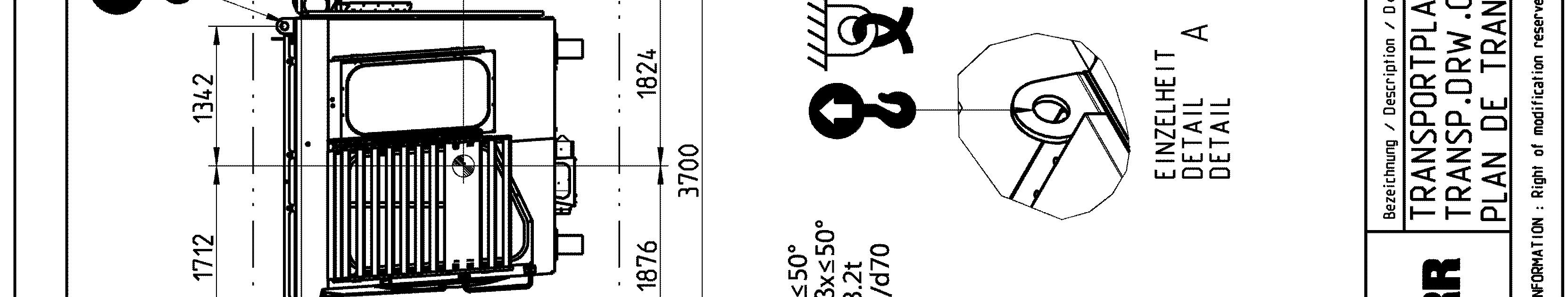
Sticker for lifting and lashing operations
Thefollowingstickerisplacednexttoeachtransportdrawingontherelatedpartand package. It shows rules and precautions which you must obey for transport operations.
The Lashing Capacity LC is the maximum force that the lashing ring can hold in accordance with the angles given on the transport drawing.
TheSafeWorkingLoadSWL isthemaximumloadthattheliftingringcanholdinaccordance with the angles given on the transport drawing.
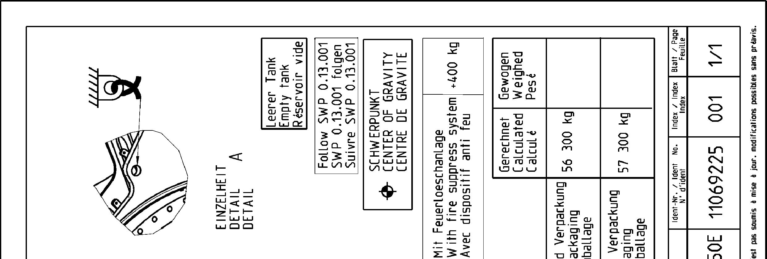
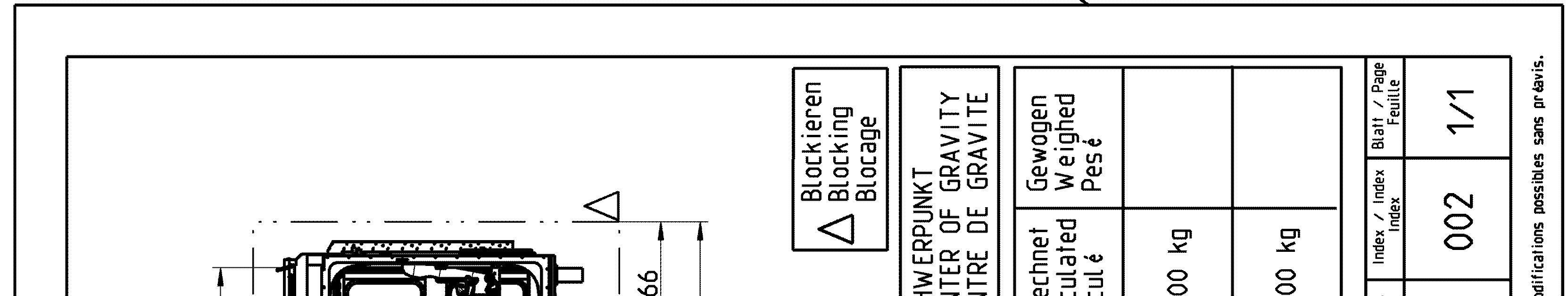
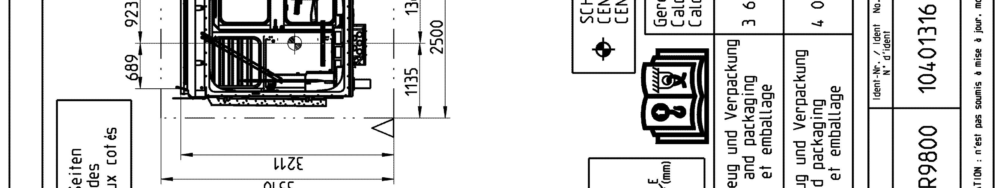
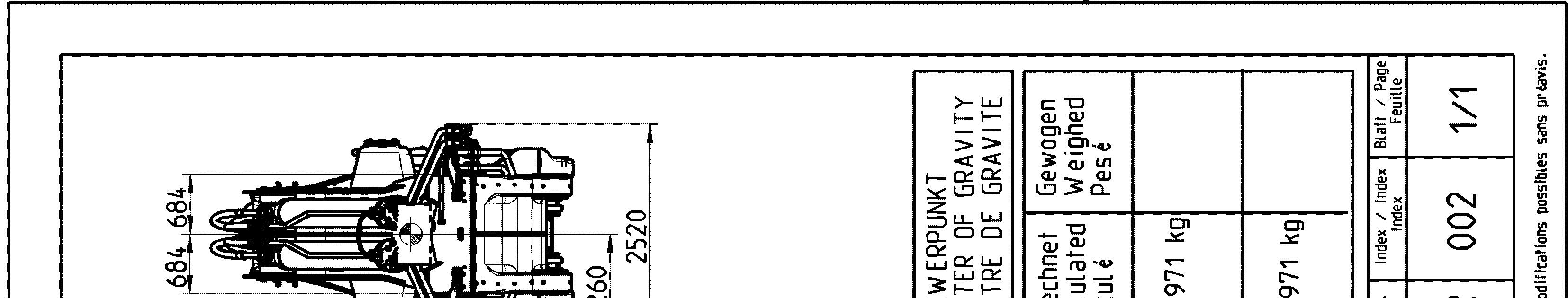
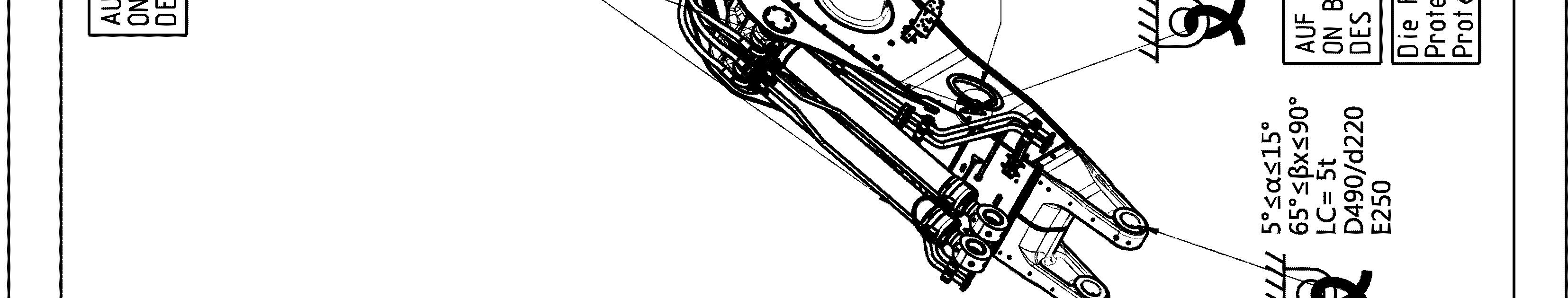
Transport drawings
The following drawings indicate the different lashing and lifting points on the elements of the excavator. Weight (with and without transport tooling and packaging), overall dimensions as well as centerof gravity are also given.
Theaimofthesedrawingsistoensuresafeoperationduringtransport,handlingand storage.
Note!
Thelashingandliftingpointsareindicatedonthe concernedelements oftheexcavator by specific labels (see § "Signs on the machine"). To be easily recognized, lifting points are painted in yellow (in red if excavator is yellow) as well.
Danger!
Theliftingpointsgivenonatransportdrawingforanelementaredesignedtoliftthis element only and nothing else.
Never lift an assembly of several elements by the lifting points of only one of these elements.