Liebher R 9400 Backhoe Attachment Hydraulic Excavator Assembly Manual - PDF DOWNLOAD

Page 1

Assembly Manual

en Assembly Manual

LEC / en / Version: 02 / 2021

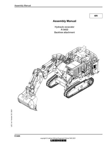
Hydraulic excavator R 9400 Backhoe attachment

R 9400 copyright © Liebherr-Mining Equipment Colmar SAS 2021

MJFCIFSS


Assembly Manual

Product identification Manufacturer:

Liebherr-Mining Equipment Colmar SAS

Type:

Assembly Manual

Conformity:

EC

Address Liebherr-Mining Equipment Colmar SAS 49 rue Frédéric Hartmann

LEC / en / Version: 02 / 2021

CS 50038, F-68025 Colmar Cedex

R 9400 copyright © Liebherr-Mining Equipment Colmar SAS 2021

MJFCIFSS


Assembly Manual Safety instructions .................................................................................................................1.00 1 2 3 4 5

Meaning of the symbols in this manual . . . . . . . . . . . . . . . . . . . . . . . . . . . . . . . . . . . . . . . . . . . . . . . . 1.00.3 Use in accordance with the regulations . . . . . . . . . . . . . . . . . . . . . . . . . . . . . . . . . . . . . . . . . . . . . . . . 1.00.4 Safety Instructions . . . . . . . . . . . . . . . . . . . . . . . . . . . . . . . . . . . . . . . . . . . . . . . . . . . . . . . . . . . . . . . . 1.00.4 Servicing the machine safely . . . . . . . . . . . . . . . . . . . . . . . . . . . . . . . . . . . . . . . . . . . . . . . . . . . . . . . 1.00.16 Conversion factors. . . . . . . . . . . . . . . . . . . . . . . . . . . . . . . . . . . . . . . . . . . . . . . . . . . . . . . . . . . . . . . 1.00.23

Excavator Assembly ..............................................................................................................2.00 1 2 3

4

5

LEC / en / Version: 02 / 2021

6

Reason for the job . . . . . . . . . . . . . . . . . . . . . . . . . . . . . . . . . . . . . . . . . . . . . . . . . . . . . . . . . . . . . . . 2.00.25 Operational Process . . . . . . . . . . . . . . . . . . . . . . . . . . . . . . . . . . . . . . . . . . . . . . . . . . . . . . . . . . . . . 2.00.26 Requirements for the assembly site . . . . . . . . . . . . . . . . . . . . . . . . . . . . . . . . . . . . . . . . . . . . . . . . . 2.00.26 3.1 Safety precaution - Secure ground selected . . . . . . . . . . . . . . . . . . . . . . . . . . . . . . . . . . . . . . 2.00.26 3.2 Persons and tools requirements . . . . . . . . . . . . . . . . . . . . . . . . . . . . . . . . . . . . . . . . . . . . . . . 2.00.26 Arrival of the machine components . . . . . . . . . . . . . . . . . . . . . . . . . . . . . . . . . . . . . . . . . . . . . . . . . . 2.00.37 4.1 Transport responsibility . . . . . . . . . . . . . . . . . . . . . . . . . . . . . . . . . . . . . . . . . . . . . . . . . . . . . . 2.00.37 4.2 Check for any missing parts . . . . . . . . . . . . . . . . . . . . . . . . . . . . . . . . . . . . . . . . . . . . . . . . . . 2.00.37 4.3 Unload components on site and parts layout . . . . . . . . . . . . . . . . . . . . . . . . . . . . . . . . . . . . . 2.00.37 Assembly process - Initial conditions. . . . . . . . . . . . . . . . . . . . . . . . . . . . . . . . . . . . . . . . . . . . . . . . . 2.00.38 5.1 General information . . . . . . . . . . . . . . . . . . . . . . . . . . . . . . . . . . . . . . . . . . . . . . . . . . . . . . . . . 2.00.38 Assembly process . . . . . . . . . . . . . . . . . . . . . . . . . . . . . . . . . . . . . . . . . . . . . . . . . . . . . . . . . . . . . . . 2.00.41 6.1 Unloading trucks / Positioning elements . . . . . . . . . . . . . . . . . . . . . . . . . . . . . . . . . . . . . . . . . 2.00.46 6.2 Opening boxes and containers . . . . . . . . . . . . . . . . . . . . . . . . . . . . . . . . . . . . . . . . . . . . . . . . 2.00.48 6.3 Pre-assembly of the cabin elevation . . . . . . . . . . . . . . . . . . . . . . . . . . . . . . . . . . . . . . . . . . . . 2.00.50 6.4 Pre-assembly of the counterweight . . . . . . . . . . . . . . . . . . . . . . . . . . . . . . . . . . . . . . . . . . . . . 2.00.58 6.5 Assembly of the valve bank on the uppercarriage. . . . . . . . . . . . . . . . . . . . . . . . . . . . . . . . . . 2.00.58 6.6 Pre-assembly of the cabin . . . . . . . . . . . . . . . . . . . . . . . . . . . . . . . . . . . . . . . . . . . . . . . . . . . . 2.00.61 6.7 Pre-assembly of the boom. . . . . . . . . . . . . . . . . . . . . . . . . . . . . . . . . . . . . . . . . . . . . . . . . . . . 2.00.63 6.8 Assembly of the undercarriage . . . . . . . . . . . . . . . . . . . . . . . . . . . . . . . . . . . . . . . . . . . . . . . . 2.00.68 6.9 Assembly of the uppercarriage . . . . . . . . . . . . . . . . . . . . . . . . . . . . . . . . . . . . . . . . . . . . . . . . 2.00.76 6.10 Assembly of the cabin elevation . . . . . . . . . . . . . . . . . . . . . . . . . . . . . . . . . . . . . . . . . . . . . . . 2.00.83 6.11 Assembly of the fuel tank . . . . . . . . . . . . . . . . . . . . . . . . . . . . . . . . . . . . . . . . . . . . . . . . . . . . 2.00.86 6.12 Assembly of the powerpack. . . . . . . . . . . . . . . . . . . . . . . . . . . . . . . . . . . . . . . . . . . . . . . . . . . 2.00.91 6.13 Assembly of the hydraulic tank . . . . . . . . . . . . . . . . . . . . . . . . . . . . . . . . . . . . . . . . . . . . . . . . 2.00.97 6.14 Assembly of the counterweight . . . . . . . . . . . . . . . . . . . . . . . . . . . . . . . . . . . . . . . . . . . . . . . 2.00.101 6.15 Assembly of the guard railing . . . . . . . . . . . . . . . . . . . . . . . . . . . . . . . . . . . . . . . . . . . . . . . . 2.00.107 6.16 Assembly of the cabin . . . . . . . . . . . . . . . . . . . . . . . . . . . . . . . . . . . . . . . . . . . . . . . . . . . . . . 2.00.109 6.17 Assembly of the boom . . . . . . . . . . . . . . . . . . . . . . . . . . . . . . . . . . . . . . . . . . . . . . . . . . . . . . 2.00.113 6.18 Assembly of the stick. . . . . . . . . . . . . . . . . . . . . . . . . . . . . . . . . . . . . . . . . . . . . . . . . . . . . . . 2.00.117 6.19 Electrical and hydraulic connections . . . . . . . . . . . . . . . . . . . . . . . . . . . . . . . . . . . . . . . . . . . 2.00.125 6.20 Oil filling . . . . . . . . . . . . . . . . . . . . . . . . . . . . . . . . . . . . . . . . . . . . . . . . . . . . . . . . . . . . . . . . . 2.00.126 6.21 First start check procedures . . . . . . . . . . . . . . . . . . . . . . . . . . . . . . . . . . . . . . . . . . . . . . . . . 2.00.127 6.22 Assembly of the cylinders . . . . . . . . . . . . . . . . . . . . . . . . . . . . . . . . . . . . . . . . . . . . . . . . . . . 2.00.128 6.23 Troubleshooting. . . . . . . . . . . . . . . . . . . . . . . . . . . . . . . . . . . . . . . . . . . . . . . . . . . . . . . . . . . 2.00.132 6.24 Assembly of the bucket . . . . . . . . . . . . . . . . . . . . . . . . . . . . . . . . . . . . . . . . . . . . . . . . . . . . . 2.00.134 6.25 Commissioning . . . . . . . . . . . . . . . . . . . . . . . . . . . . . . . . . . . . . . . . . . . . . . . . . . . . . . . . . . . 2.00.140

R 9400 copyright © Liebherr-Mining Equipment Colmar SAS 2021

MJFCIFSS


LEC / en / Version: 02 / 2021

Assembly Manual

R 9400 copyright © Liebherr-Mining Equipment Colmar SAS 2021

MJFCIFSS


Assembly Manual

Safety instructions Meaning of the symbols in this manual

1.00: Safety instructions Working with the machine holds dangers to which you as the owner, machine operator or maintenance expert could be exposed. If you regularly read and note the safety information, however, you can prevent danger and accidents. This is particularly true for those who are only occasionally in contact with the machine, e.g. for maintenance work. The following information comprises safety regulations which, if followed conscientiously, will contribute to your safety and that of other persons, as well as avoiding damage to the machine. Following these precautions does not release you from the responsibility to take note of safety regulations which apply on site or of guidelines given by legal bodies or professional associations. For EU countries, guideline 2009 / 104 / EC contains the minimum required safety information applicable to the owner.

1

Meaning of the symbols in this manual Work processes and actions that could cause danger are accompanied by safety informations in these operating instructions. These safety informations describe various dangers which are emphasized by the terms Danger, Caution and Note. These terms are identified by symbols in the operating instructions and have the following meaning: Danger! Warning relating to a danger that carries with it a high risk of death or serious injury if the appropriate preventative measures are not taken. Caution! Warning relating to dangers that could result in physical injury and/or damage to the machine if the appropriate preventative measures are not taken.

Note! This symbol identifies user tips and operating and maintenance procedures whose use will guarantee a high degree of user-friendliness and longevity to the machine or which will considerably simplify working procedures. – This symbol identifies a listing. • This symbol identifies a sub-listing. This symbol signifies the following: “The precondition must be fulfilled”. The machine operator or the maintenance personnel must first fulfil the precondition described, i e. the machine must be brought into a particular work position in order to be able to carry out the actions subsequently described. LEC / en / Version: 02 / 2021

This symbol identifies an action. The machine operator or the maintenance personnel should be active at this location and carry out the action described. This symbol means “Carry out an activity". If the machine operator or maintenance personnel have carried out the activities described in an action, the result of this action will be described here. Following these notes does not relieve you of responsibility for following additional rules and guidelines! Additional points that should be noted are: – The safety regulations which apply on site – Statutory road traffic regulations

1.00.3

R 9400 copyright © Liebherr-Mining Equipment Colmar SAS 2021

MJFCIFSS


Safety instructions

Assembly Manual

Use in accordance with the regulations – The guidelines provided by professional associations.

2

Use in accordance with the regulations – The hydraulic excavator is a machine with work equipment (e.g. hoe type bucket, grab, bucket attachment) designed to detach, lift, transport and shake off earth, stones and other materials, while the transportation of the load itself usually takes place without moving the machine. Moving the machine when it is carrying a load must be carried out while observing the appropriate safety measures (see section "Notes for safe working"). – Machines used for hoisting are subject to specific conditions and must be fitted with special safety devices (for further information, see section “Hoisting work” or contact Liebherr customer service). – Demolition machines can have attachments and special tools that are specially made to demolish, cut, loosen, separate or break into parts buildings or structures, collect, transport and sort demolition waste. Thus, machines used for demolition application are subject to specific conditions and must be fitted with special safety devices (for further information, contact Liebherr customer service). – Machines used underground (deep mining and tunnel construction) must be equipped with exhaust gas reducing equipment (e.g. diesel particle filter). Always comply with the statutory regulations applicable at the location of operation. – Special tasks require special attachments and possibly also special safety devices. This equipment may only be attached to the machine and used with the explicit consent of and according to the instructions of the manufacturer of the basic machine. – Any other use, in particular transporting persons or working in explosive atmospheres or contaminated environments is not deemed to be in accordance with regulations. The manufacturer is not liable for any damage resulting from this action. The user is solely responsible for the risk incurred. – Observing the operating instructions and the inspection / maintenance instructions is also deemed to be appropriate use in accordance with regulations.

3

Safety Instructions

– Please familiarize yourself with the operating instructions before starting up the machine. – Ensure that you have obtained, read and understood any additional instructions relating to special accessories for the machine. – Only specifically authorized persons may operate, maintain or repair the machine. The legal minimum age is to be adhered to. – Only employ trained or appropriately instructed personnel. Clearly establish which personnel are responsible for operating, setting up, maintaining and repairing the machine. Give personnel the power to refuse to carry out unsafe instructions. This also applies in relation to traffic regulations. – Only permit apprentices and personnel who are in training or who have only general training to operate on the machine under the constant supervision of an experienced member of staff. – As far as possible, monitor personnel to ensure that they are adhering to safe working practices, are aware of risks and are observing the operating instructions. – Always wear safe work clothes when you are working on or with the machine. Avoid wearing rings, wrist watches, ties, scarves, open jackets, baggy clothing etc... There is a risk of injury from, for example, getting caught up or being drawn in. – Wear individual protective equipment (protective goggles, safety helmets, safety shoes and gloves, reflective vests and ear protection etc....). – Ensure that you obtain information on any special safety regulations for the job site from the site foreman. – Always tilt up the safety lever before leaving the operator’s seat. – When getting in and out, do not hold on to the steering column, control panel or joystick. Doing this could cause unintentional movement, which could result in an accident.

1.00.4

R 9400 copyright © Liebherr-Mining Equipment Colmar SAS 2021

MJFCIFSS

LEC / en / Version: 02 / 2021

General safety instructions


Assembly Manual

Safety instructions Safety Instructions

– Never jump from the machine; use the steps, ladders, gangplanks and supporting straps provided for this purpose. – Face the machine when getting in or out and always use three-point support, i.e. two hands and one foot or two feet and one hand must always be in contact with the access system at the same time. – Familiarize yourself with the location of the emergency exit. – In the absence of any other instructions, proceed as follows for all maintenance and repair work: • park the machine on firm, level ground • align the uppercarriage with the undercarriage so that the sprockets locate at the back-end • anchor the bucket in the ground. • place all operating levers into neutral and tilt the safety lever up. • switch off the engine and remove the start key. – Before touching any parts of the hydraulic circuits, you must also operate all pilot control devices (joystick and pedals) in all directions with the start key in contact position and with the security lever lowered, in order to reduce the actuating and dynamic pressures in the work circuits. You must then reduce the internal tank pressure as described in these operating instructions. – Secure all loose parts on the machine. – Never operate a machine before carrying out a careful inspection tour and checking whether any warning signs are missing or illegible. – Respect all danger and safety instructions. – For special applications the machine must be equipped with specific safety equipments. Work only if they are mounted and functional. – Do not carry out any modifications, alterations or conversions to the machine which may affect safety without the express permission of the manufacturer. This also applies for the installation of safety devices and valves and for welding work on load-bearing parts. – It is forbidden to repair or alter any operator protective structure (for example, structure of the cab, FOPS, ROPS, TOPS). – Ensure that any damaged operator protective structure is immediately replaced. – Not original equipment and component parts or such kind, which has generally not been validated by Liebherr for installation or extension, has not to be installed or added onto the excavator without previous written agreement of Liebherr. Wherefore the necessary technical documentations has to be at Liebherr’s disposal.

Avoidance of crushing and burns – – – – –

LEC / en / Version: 02 / 2021

– – – – –

Do not work beneath the attachment if it is not safely positioned on the ground or supported. Do not use any damaged or insufficient load-bearing take-up materials, such as ropes or chains. Wear adapted work gloves when working with wire cables. When working on the attachment, never use your fingers to locate bores; use the correct punch for the procedure. Ensure that no objects enter the fans when the engine is on. The fan will eject or destroy these objects and will itself be damaged. Near operating temperature, the parts of the engine cooling system, of the exhaust system and of the hydraulic system can reach very high temperatures. Avoid coming into contact with coolant carrying parts, with parts from the exhaust system and with hot oil or oil-bearing parts. There is a risk of sustaining burns. Only check the coolant when the sealing cap of the expansion container has cooled to a point where it is possible to touch it. Then turn the cap carefully to let off the overpressure. Wear protective goggles and gloves when working on the battery. Avoid sparks and naked flames. Never permit the bucket to be guided by hand by auxiliary personnel. When reaching into the engine compartment, always secure the side doors against unintentional closing by positioning the supports if provided for this purpose. Never lay under the machine if it is raised with work attachment and has not been correctly and securely supported with appropriate supports.

1.00.5

R 9400 copyright © Liebherr-Mining Equipment Colmar SAS 2021

MJFCIFSS


Safety instructions

Assembly Manual

Safety Instructions

Avoidance of fire and explosions – Switch off the engine when refuelling. – Do not smoke or use a naked flame when refilling tanks and working near or charging the batteries. – Always start the engine in accordance with the operating instructions. – Check the electrical system regularly. – Have all faults, such as loose connections, blown fuses and lamps and clogged or abraded cables rectified by authorized personnel. – Do not transport any combustible liquids anywhere on the machine other than in the tanks provided for this purpose. – Check all lines, hoses and screwed joints regularly for leakage and damage. – Rectify leakages immediately and replace damaged components. – Oil spraying out of leaking areas can easily cause a fire. – Ensure that all holds and shields are correctly installed to guard against vibration, abrasion and heat accumulation. – Do not use cold start materials (ether) in the vicinity of heat sources, naked flames or in inadequately ventilated areas. – Do not use any starting aids containing flammable material to start diesel engines with preheating or flame glow systems. There is a risk of EXPLOSION. – Familiarize yourself with the location and operation of fire extinguishers on the machine and with local fire warning and fire abatement options. – It is possible to install an extinguisher into the driver’s cab. – All doors, covers and boxes locks have to be unlocked before operation in order to facilitate firefighting in case of fire. Only electrical boxes from and over 50V must remain locked during operation.

Bringing the machine safely into service

Safely getting up – Proceed with the same precautions to climb up or down onto the machine, as to install yourself at the operator’s seat. – When getting up or down, position the machine on even, horizontal ground. The upper structure should be positioned with the undercarriage in such a way that the steps and ladders are aligned with each other.

1.00.6

R 9400 copyright © Liebherr-Mining Equipment Colmar SAS 2021

MJFCIFSS

LEC / en / Version: 02 / 2021

– Carry out a careful inspection tour around the machine each time before starting it. – Ensure that no one, except an authorized person, is in the work and movement area of the machine. – Check the machine for loose bolts, cracks, wear, leakage and damage. – Never attempt to operate a damaged machine. – Ensure that any damage is immediately rectified. – Ensure that all hoods and covers are closed, but that locks are unlocked, to facilitate the fight against fire in case of. – Ensure that all warning signs are present. – Keep windows and interior and exterior mirrors clean. Secure doors and windows against unintended movement. – Ensure that no one is working on or under the machine and warn personnel in the vicinity of the machine that it is about to start by sounding the horn.


Assembly Manual

Safety instructions Safety Instructions

– Ensure that steps, ladders and hand-rails (grips) are in good condition. In particular, you should ensure that they are free of dirt, oil, ice and snow. NOTE: To ensure that the doors open properly in all weather conditions, the door seals must be dusted with talc or silicon at least every two months or more often if required. The door hinges and locks should be greased regularly. – Face the machine when getting in or out and always use three-point support, i.e. two hands and one foot or two feet and one hand must always be in contact with the access system at the same time. – If you are able to reach the door handle with your free hand, open the doors before you climb any higher. External influences, such as wind, can make it more difficult to open doors. Because of this, always use your hand for control when opening doors. Ensure that the door is latched open to prevent it slamming open and shut. – In case of bad weather conditions, be particularly vigilant to realise the climbing and descent from the cab with the best safety conditions, and do or give the instructions to the execution of prior preparations to be accomplished, as enunciated above, in order to displace yourself safely. – Be particularly vigilant with those prerequisites conditions. – For cab with a side door: • Now continue to climb up, still using the three-point support and sit down in the operator’s seat as soon as you enter the cab. • Fasten the safety belt (if available), unlock the door, using the planned lever, and close it immediately using the door handle, before tilting down the safety lever, and start the machine. • If you wish to work with the door open, it is necessary to fasten your safety belt. If unavailable, let it be installed before working with the door open. – For cab with a rear door: • Now continue to climb up, still using the three-point support and close the door as soon as you enter the cab. • Sit down in the operator’s seat and fasten the safety belt (if available) before tilting down the safety lever, and start the machine. Adjusting the operator’s standing position – Before starting the machine, adjust the seat, mirrors, armrests and operator’s controls in such a way that you are able to work comfortably and safely. – Acoustic insulation devices on the machine must be set to the insulation position throughout operation. Protection from vibration - seat adjusting – Keep the seat in good condition and adjust it as follows: • The seat and its damping action should be adjusted depending on the weight and height of the operator. • Check the seat’s damping action and adjustment mechanisms regularly and ensure that these seat characteristics remain as per the seat manufacturer’s instructions.

LEC / en / Version: 02 / 2021

Utilisation in confined spaces – Only operate combustion engines and fuel-operated heaters in adequately ventilated spaces. Before starting in closed areas, ensure adequate ventilation. Follow the regulations which apply for the particular area of use.

Starting the machine safely – Before starting, check all control lamps and instruments for correct function, place all operator’s controls in Neutral and tilt the safety lever up. – Before starting, sound the horn briefly to alert people in the vicinity of the machine. – Only start the machine from the driver’s seat. – In the absence of any other instructions, start the engine in accordance with the regulations given in the operating instructions. – Tilt the safety lever down and then test all display and checking devices.

1.00.7

R 9400 copyright © Liebherr-Mining Equipment Colmar SAS 2021

MJFCIFSS


Safety instructions

Assembly Manual

Safety Instructions – In enclosed spaces, only allow the engine to run when there is adequate ventilation. If necessary, open doors and windows to ensure sufficient fresh air supplies. – Bring the engine and hydraulic oil to operating temperature. Low oil temperatures make the control unit react sluggishly. – Check that the attachment is operating correctly. – Move the machine carefully to an open area and then check the function of the travel and swing gear brakes, the steering and the signalling and lighting devices. Lighting devices must always be clean.

Stopping the machine safely – Only stop the machine on level, firm ground. – If the machine has to be stopped on an incline, chocks should be used to secure it from rolling away. – Before stopping the machine, each time it is possible, align the uppercarriage with the undercarriage so that the sprockets locate at the back-end. This is the only one position which enables a secured access to every maintenance locations on the uppercarriage. – Use the stop bolts to secure the uppercarriage facing the undercarriage, if available. – Lower the attachment and anchor the grab lightly in the ground. – Position every control lever into neutral position and apply the travel and swing brakes. – Stop the engine in accordance with the operating instructions and tilt the safety lever up before leaving the cab. – Lock the machine, included hoods and compartments, remove every keys and secure the machine against unpermitted use and vandalism.

Safely getting down – Proceed with the same precautions to climb up or down onto the machine, as to install yourself. – Stop the machine on level, horizontal ground. The upper structure should be positioned with the undercarriage in such a way that the steps and ladders are aligned with each other. – Open and lock the door. Be sure of it’s locking. Take care of weather conditions ! Unfasten the safety belt. – Position yourself with your face toward the machine when getting out and use three-point support, i.e. two hands and one foot or two feet and one hand must always be in contact with the access system at the same time. Climb down until you can close the doors safely. Always use your hand for control when closing the doors. Lock the door. – Now climb down to the ground.

– Before you start working, acquaint yourself with the special features of the job site and any special precautions and warning signals. Examples of particular work environments would be on-site or traffic obstructions, the load-carrying capacity of the ground and any requirements to make the job site safe from public use. – Always maintain a safe distance from overhangs, edges, slopes and unsafe ground. – Be particularly careful in conditions of reduced visibility and changeable ground conditions. – Familiarize yourself with the location of power and gas lines on the job site and take particular care when working near them. If necessary, inform the responsible authorities. – When working in areas with underground lines (gas, electricity), adhere to the laws, regulations and rules applicable at the place of use. – Maintain a safe distance from electrical aerial lines. Do not allow the attachment to come near cables when working near electrical aerial lines. Risk of fatality! Inform yourself about required safety distances. – The following actions must be carried out in the event of any transfer of electricity: • do not move the machine or its attachment,

1.00.8

R 9400 copyright © Liebherr-Mining Equipment Colmar SAS 2021

MJFCIFSS

LEC / en / Version: 02 / 2021

Working safely with the machine


Assembly Manual

Safety instructions Safety Instructions

– – – – – – – – – – –

– –

– – – – – – – –

LEC / en / Version: 02 / 2021

– –

• do not leave the driver’s cab, • warn any personnel in the vicinity not to come close to the excavator and not to touch it, • instruct or initiate that someone turns off the voltage. • move the machine, if possible, from the danger zone to a sufficient distance, • Do not leave the machine until you are absolutely sure that voltage in the line, which had been touched or damaged, has been turned off! Before moving the machine, always ensure that any attachments are safely secured. When driving onto public roads, paths and squares, observe current traffic regulations and if necessary, ensure that the machine has been made safe as per regulations beforehand. Always turn on the lights in conditions of poor visibility or darkness. Do not permit any passengers in the machine. Only work when seated properly and with the safety belt securely fastened (if available). Report all function faults and ensure that all necessary repairs are carried out immediately. Assure yourself that no one is endangered when you start the machine moving. Before you start working, test the brake system in accordance with the regulations given in the operating instructions. Never leave the driver’s seat while the machine is moving. Never leave the machine unattended while the engine is running. The machine must be positioned, moved and operated in such a way that it is stable and that there is no danger of overturning. Only known loads may be moved with the attachment; this applies particularly when using the grab. Position the upper structure in the longitudinal direction when moving and hold the load as close to the ground as possible. EXCEPTION: excavators used for loading and unloading, see the part “Safe use when loading and unloading (particularly when loading and unloading wood)” on page 12. Adjust your driving speed to suit site conditions. Avoid any working movements which may tip the machine. Should the machine start to tip or slide sideways, however, turn the upper structure to face downhill and lower the attachment at the same time. As far as possible, work downhill or uphill and not side on to the slope. Drive safely on stony, slippery or inclined ground. Always travel in the direction of the slope and not perpendicular to the slope, with the uppercarriage aligned with the undercarriage. Only drive downhill at the permitted speed or you could lose control of the machine. Always shift down to a lower running step before a slope. When doing this, the diesel engine must run at maximal speed and the speed may only be reduced using the foot pedals. Load an occupied truck only if all safety requirements are fulfilled, notably in order to protect the truck operator. For demolition work, digging and crane operations etc., always use protective devices specifically designed for the purpose. For terrain which is difficult to gain an overview of and whenever necessary, ask for the assistance of a spotter. Only permit one person to give you signals. Authorize only experienced people to attach load and to give indications to the machine operator. This people must be in the operator’s sight or in radio contact with him. Depending on the attachment combination, there is a risk of collision between the work tool and the machine (uppercarriage and undercarriage). The greatest degree of care must be taken to avoid damage. Depending on the attachment combination, there is a risk of collision between the work tool and the cab, the cab protection or the boom cylinders. The greatest degree of care must be taken to avoid damage when the hoe teeth come within this area. Depending on the attachment combination, there is a risk of collision between the work tool and the attachment parts. The greatest degree of care must be taken to avoid damage.

1.00.9

R9 copyright © Liebherr-Mining Equipment Colmar SAS 2021

MJFCIFSS


Safety instructions

Assembly Manual

Safety Instructions – Depending on the attachment combination, there is a risk of collision between the lift ring of the attachment and the cab or the cab protection. Before operating, ensure that there is no risk of collision, especially on excavator with cab elevation. If necessary remove the lift ring. – In case of a thunderstorm: • lower the attachment to the ground and if possible anchor the digging tool into the soil. • leave the cab and move away from the machine before the storm breaks out. Otherwise, you must stop the excavator, turn off the radio and keep inside the closed cab until the end of the storm. – Auxiliary control units can have various functions. Always check their functions when starting up the machine. – Stop the swinging motion of the uppercarriage when lowering the attachment into a ditch without striking the attachment on the ditch walls. – Inspect the machine for damage if the attachment has been swung into a wall or any other obstacles. – Applications in which the attachment is to be used to strike the material being extracted are not permitted, even when working in a longitudinal direction. – Repeated strikes against an object leads to damage to the steel structures and machine components. – Please refer to your Liebherr dealer if special teeth for heavy-duty or special applications are required. – Do not attach too large bucket or bucket with side cutters or that are during operations with rocky material. This would prolong the work cycles and may lead to damage to the bucket as well as further machine components. – With the 2x45° offset articulation, the offset position may only be employed if the working tool or the attachment does not touch the material. – Operation of the offset articulation to drill into the material is not permitted. – Do not lift the machine during operation. Should this happen, lower the machine slowly back to the ground. – Do not let the machine fall heavily on the ground and do not hold it back with the hydraulics. This would damage the machine. – During operation with the attachment it is forbidden to raise the machine with the dozing blade (e.g. carving at the ceiling when tunnelling). – Do not dig under the undercarriage. Take all necessary measures to prevent ground collapse under the machine. – The operation of Liebherr Mining machines in the following Mining applications is not approved or condoned by Liebherr: • Batter pulling (also known as Scaling), without exception. • Double benching (also known as Split benching or Double flitching) when the material is unblasted and non-fragmented material which requires the boom down (rod side) pressure to exceed 50 bar.

Working safely with the machine used for demolition application – Machines used for demolition application are subject to specific conditions and must be fitted with special safety devices (for further information, contact Liebherr customer service). – If the machine can be used for demolition application, you must also obey the additional safety instructions that follow. Before the operation of the machine – Make sure that no persons are in the hazard area of the machine. – Make sure that the working conditions are in the specified limits.

1.00.10 copyright © Liebherr-Mining Equipment Colmar SAS 2021

MJFCIFSS

LEC / en / Version: 02 / 2021

The use of these Mining methods will result in increased fatigue levels to steel structures and components of the respective Liebherr Mining Machine and therefore will significantly reduce the expected lifetime of structures and/or components.


Assembly Manual

Safety instructions Safety Instructions

– Make sure that the special safety devices necessary for the task operate correctly. – Always obey the applicable local regulations. Incorrect use of the machine used for demolition application – Demolition works must be carried out only by trained specialist personnel. – Do not operate the machine if the counterweight is not suitable for the attachment or special tool you use. – Do not operate the machine if applicable and approved operator protective structures (e.g. FOPS, front protective grid) are not installed. – Do not move suddenly and jerkily. Do not stop it suddenly. Always move the attachment or special tool slowly and with constant speed movements. – Because of the possible effects on the machine stability, reduce the height and the speed of the movement. – Do not lift the machine with the attachment or special tool. – Make sure that there is no rubble on the attachment or special tool. – Operate the machine in the position that follows: • Align the uppercarriage with the undercarriage so that the sprockets locate at the back-end. • Work over the idler. – Keep a sufficient distance between the machine and the object to demolish. – Do not use the inertia of the attachment or special tool as an additional force. – Never leave the machine unattended while the attachment or special tool is not safely positioned on the ground. – Lay down the attachment or special tool on the ground to park the machine. – Obey the symbols shown on the display and the acoustic warning signals. – Prevent unwanted lateral forces on the attachment or special tool when the uppercarriage turns. – Do not drive at a right angle to the slope. Incorrect use of the attachment or special tool used for demolition application – Make sure that you use an attachment or special tool exclusively designed for the task. – Only use attachment or special tool approved by Liebherr. – Only operate the attachment or the special tool with closed windshield and with a front protective grid. – Only operate the attachment or the special tool with closed door. – Do not clean the ground with the special tool. – Make sure that the special tool works in its specified limits. For more information, also refer to the Operator’s Manual of the tool manufacturer.

LEC / en / Version: 02 / 2021

Safe use of a hydraulic hammer or a hydraulic ripper – According to the severity of the application, the use of a hydraulic hammer or a hydraulic ripper can result in vibrations, shocks or stresses which are higher than in normal use. It may reduce the expected lifetime of structures and/or components. – The hydraulic hammer or the hydraulic ripper must be selected with particular care. When using a hydraulic hammer or a hydraulic ripper not permitted by Liebherr, warranty for steel structures and machine components will be ceased. – Before beginning breaking tasks, position the machine on firm and level ground. – Use a hydraulic hammer or a hydraulic ripper designed exclusively for breaking stone, concrete and other breakable materials. – Only operate the hydraulic hammer or the hydraulic ripper in the longitudinal direction of the machine and with the windshield closed or with a front protective grid. – Ensure during hammer or ripper operation that no cylinder is entirely extended or retracted and that the stick is not in the vertical position.

1.00.11 copyright © Liebherr-Mining Equipment Colmar SAS 2021

MJFCIFSS


Safety instructions

Assembly Manual

Safety Instructions – In order to avoid damages to the machine, try not to break stone or concrete while performing retraction and extension motions of the hydraulic hammer. – Do not apply the hydraulic hammer uninterrupted for more than 15 seconds at a time to the same place. Change the breaking point. Too long uninterrupted operation of the hydraulic hammer leads to an unnecessary overheating of the hydraulic oil. – Do not use the drop force of the hydraulic hammer or of the hydraulic ripper to break stone or other materials. Do not move obstacles with the hydraulic hammer. Misuse of this nature would damage both the hammer and the machine. – Do not use the hydraulic hammer or the hydraulic ripper to lift objects. – Before beginning breaking tasks, the pressure of the dampening accumulator of the hydraulic ripper must be adjusted depending on the nature of the ground and the excavator model.

Safe use of a ripper – Rippers are generally used in applications where the use of a bucket is not efficient to break out rocks. Thus, these applications are more severe than in normal use. – According to the severity of the application, the use of a ripper can result in vibrations, shocks or stresses which are higher than in normal use. It may reduce the expected lifetime of structures and/or components. – Special hydraulic devices can be necessary. Contact the Liebherr customer service. – The ripper must be selected with particular care. When using a ripper not permitted by Liebherr, warranty for steel structures and machine components will be ceased. – Before beginning breaking tasks, position the machine on firm and level ground. – Do not use the ripper to lift objects.

– According to use, it can be necessary when working with a grab to move with the attachment raised and the load lifted up; this applies, for example, when loading and unloading wood. – Here, the centre of gravity of the machine will be displaced upwards in the vertical direction. The driving characteristics of the machine will thus be influenced persistently, e.g. through reduction of the dynamic stability. The following instructions are therefore to be observed at all times: • Adjust vehicle handling to suit the altered machine characteristics and environmental conditions. • Reduce your speed to prevent the need for sudden braking and steering manoeuvres. • Avoid sudden speed changes, such as braking, accelerating and changing direction. • Only rotate the uppercarriage when the undercarriage is stationary. • Only rotate the uppercarriage after you have picked up the load. • Only move the machine when you have picked up and lifted the load and rotated the upper structure to the driving position. • There is a danger of possible swinging movement and dropping of the load when the attachment is raised. • A protective grid (FOPS) in accordance with ISO 10262 must be attached to the cab. • A protective roof (FOPS) in accordance with ISO 10262 must be attached if there is a risk of objects falling from above. • Only the maximum permissible load may be taken up using the grab. – NOTE: The weight of absorbent materials, such as logs, is dependent on length, diameter and specific weight. The influencing variables present in a natural product, such as moisture, must be noted. – Working procedures when using machines with grabs require the machine operator to receive special instruction and training. – Use as part of the work process is only permitted when the machine operator has sufficient training and practical experience.

1.00.12 copyright © Liebherr-Mining Equipment Colmar SAS 2021

MJFCIFSS

LEC / en / Version: 02 / 2021

Safe use when loading and unloading (particularly when loading and unloading wood)


Assembly Manual

Safety instructions Safety Instructions

Safe use of machines with tower elevation – Due to the tower elevation, the centre of gravity of the machine will be displaced upwards in the vertical direction. The driving and work characteristics of the machine will thus be influenced persistently, e.g. through reduction of the dynamic stability. – Due to the heightened centre of gravity, the machine must be aligned horizontally before use. In horizontal alignment, the centre of gravity of the uppercarriage is over the centre of the undercarriage, which reduces the risk of tilting. – The machine can still sway and tilt despite being aligned! The following instructions are therefore to be observed at all times: When moving the machine: • Rotate the uppercarriage parallel to the undercarriage (transport position). • Draw the attachment as close as possible to the machine. • Only at this point may the support feet be retracted and the machine moved. • Moving with loads is not permitted. • Check the terrain to be covered to ensure that the ground is solid and even. Potholes and uneven surfaces jeopardize the stability of the machine. • Adjust vehicle handling to suit the altered machine characteristics (high centre of gravity) and environmental conditions. • Reduce your speed to prevent the need for sudden braking and steering manoeuvres. • Avoid sudden speed changes, such as braking, accelerating and changing direction. • Ascending gradients and obstacles may only be approached in the longitudinal direction in order to prevent unacceptable banking of the machine. • Special care should be taken when driving through narrow passages - drive slowly! When loading and unloading: • The machine must be supported and aligned horizontally before moving (swing) the uppercarriage out of the transport position. • It is imperative that you check the contact surface of the support (load carrying capacity of the substrate). A support subsiding would have disastrous consequences! • Carry out all movements with increased care. • To slew the load, move the attachment as close as possible to the machine (Caution! swinging grab) and hold the load close to the undercarriage and above the substrate. • Avoid braking or accelerating the attachment or uppercarriage abruptly. • Do not lift any loads which are heavier than those given in the load chart.

Protection from vibration – Vibrational loads on mobile building machinery are mainly the result of the type and method of use. The following parameters in particular are decisive influences: • Terrain conditions: Uneven areas and potholes; • Operational techniques: Speed, steering, brakes, controlling the machine’s control elements when driving and working. – To a large extent, the machine operator determines the vibrational loads since he selects the speed, gearbox ratio, working method and route himself. This means that there is a wide range of different vibrational loads for the same machine type. LEC / en / Version: 02 / 2021

Whole-body vibrational load for the machine operator can be reduced if the following recommendations are observed: – Select suitable machines, attachment parts and auxiliary devices for each part of the job. – Use a machine that has a suitable seat (i.e. for earth-moving machinery such as hydraulic excavators, this should be a seat which corresponds with EN ISO 7096). – Keep the seat in good condition and adjust it as follows: • The seat and its damping action should be adjusted depending on the weight and height of the operator. • Check the seat’s damping action and adjustment mechanisms regularly and ensure that these seat characteristics remain as per the seat manufacturer’s instructions.

1.00.13

R 9400 copyright © Liebherr-Mining Equipment Colmar SAS 2021

MJFCIFSS


Safety instructions

Assembly Manual

Safety Instructions – Check the maintenance status of the machine, particularly with respect to: tyre pressure, brakes, steering, mechanical connections etc. – Do not steer, brake, accelerate, shift gears, move or load the machine’s attachment jerkily. – To reduce vibrational load, adjust the machine speed to suit the route as follows: • Reduce speed when driving on difficult terrain; • Drive around obstacles and avoid driving on very difficult terrain. – Keep the terrain on which the machine is working and driving in good condition: • Remove large stones and obstacles; • Fill in ruts and holes; • Have machines ready to prepare and maintain suitable ground conditions and calculate in sufficient time to carry out any work required. – Drive longer distances (e.g. on public roads) at an appropriate (medium) speed. – Use special auxiliary systems (if available) which reduce vibration for machines that are driven frequently. If such auxiliary systems are not available, regulate speed to avoid "oscillating" the machine.

Towing the machine safely – Always follow the correct procedure if applicable. – The machine may only be towed in exceptional circumstances, e.g. in order to move the machine away from an area where it is at risk. – Before towing, check all attachments and towing devices for safety and stability. – Towing devices such as bars, cables or ropes must have adequate tensile strength and should be secured around the undercarriage tower or the towing hook provided on the undercarriage. Any damage or accidents which occur while towing the machine are not covered by the manufacturer’s guarantee. – Ensure that there is no one in the vicinity of the towing devices when towing. – Stretch safely and hold the towing devices. Avoid kinks on cables or ropes. – When towing, maintain the correct transport position, permitted speed and route, and avoid lurching. – After towing, return the machine to correct operational status. – When restarting the machine, be sure only to proceed in accordance with the operating instructions.

– Equipment or attachments made by other manufacturers or those which do not have general approval from Liebherr for installation or attachment may not be installed or attached to the machine without Liebherr’s prior written consent. – Liebherr must be provided with the appropriate technical documentation necessary for this purpose. – Before carrying out any major repair work on the attachment, position the machine on level, firm ground. – Do not work beneath the equipment if it is not safely positioned on the ground or supported with appropriate supports. – Before loosening lines or unscrewing bolts, you must store the equipment, switch off the engine and press the start key to the contact position and both joysticks and the pushbuttons to “Turn grapple” in order to reduce the pressure in the hydraulic system. – Do not attempt to lift heavy parts. Use devices which are suitable for this purpose and which have sufficient load carrying capacity. – Do not use cable which is damaged or does not have sufficient load carrying capacity. Wear work gloves when working with wire cables. – When working on the attachment: switch off the engine and keep the safety lever tilted up. Never use your fingers to locate bores; use the correct punch for the procedure.

1.00.14

R 9400 copyright © Liebherr-Mining Equipment Colmar SAS 2021

MJFCIFSS

LEC / en / Version: 02 / 2021

Attaching and removing attachment parts safely


Assembly Manual

Safety instructions Safety Instructions

– During repair work: ensure that the hydraulic lines are secured correctly and that all bolts and connections are tight. – When you have removed and chocked an attachment part, close open areas of the hydraulic circuit to stop dirt entering. Only allow authorized persons in the vicinity of the machine or the lifting device used.

Removing and installing attachment pins safely – If possible, always use a hydraulic bolt press to press out the attachment’s bolts. – If you have to remove a bolt using a sledge-hammer, a driving punch and a bore hole conductor held by another person must be used. – To drive in a bolt, screw the drive screws provided in the toolbox if provided into the bolt's threaded hole and only hammer these screws. – When installing bolts locked by means of castle nuts and cotter pins, first drive the bolt to the stop, then screw the castle nut by hand until contact and then only pull it far enough to push in the cotter pin.

Transporting the machine safely

LEC / en / Version: 02 / 2021

– Due to transport restrictions, use only suitable means of transport and lifting devices with sufficient load-carrying capacity. – Park the machine on a flat surface and wedge the crawler or wheels securely. – If required, detach a part of the machine’s working attachment during transportation. – The ramp used to drive the machine up onto the flatbed trailer should not exceed an inclination of the angle value indicated in the "Technical data" section of this manual (machine must be able to walk up unaided) and should have a wooden cover to prevent sliding back. – The undercarriage should be swept clean, i.e. before driving up the ramp, clean any snow, ice and mud from the crawler / wheels of the machine. – Align the machine precisely with the loading ramp. – Attach the hand levers for fine-tune driving (crawler excavator) onto the travel pedals. – Ensure that a spotter gives the machine operator the required signal. – Prepare the placing block to ensure against rolling back when the machine is driving up onto the flatbed. – Tilt the attachment up and drive up the loading ramp. While doing this, always hold the attachment securely over the loading area, drive very carefully up the ramp and onto the transportation vehicle. – Rotate the uppercarriage carefully to the rear and lower the attachment. Due to restrictions during transport on hoe attachment, tilt the arm in and dismantle the bucket during transportation. – After loading the machine onto the flatbed trailer, the upper structure must be secured facing the undercarriage using the stop bolts (only A devices). – Secure the undercarriage and the remaining individual parts using chains and blocks to prevent slipping. – Before you leave the machine, reduce pressure on all pressure lines, remove the ignition key and tilt up the safety lever. – Lock all cab and panel doors. – Before transportation, find out all details about the route to be travelled, particularly as they relate to width, height and weight restrictions. – Pay particular attention when driving under electrical lines and bridges and through tunnels. – When unloading the machine, take the same amount of care as was taken when it was loaded. Remove all chains and blocks. Start the engine as per the operating instructions. Drive carefully off the trailer’s loading area and down the ramp. Hold the working attachment as securely as possible over the ground while doing this. Have a spotter guide you.

1.00.15

R 9400 copyright © Liebherr-Mining Equipment Colmar SAS 2021

MJFCIFSS


Safety instructions

Assembly Manual

Servicing the machine safely

4

Servicing the machine safely

– Maintenance and repair work may only be carried out by specially trained personnel. – Observe statutory timetables or intervals given in the operating instructions for repeat tests / inspections. It is imperative that a suitably equipped workshop is available in order to carry out maintenance work. – The inspection and maintenance schedule given at the end of these operating instructions defines precisely who is required / permitted to carry out what work. Jobs listed as daily / weekly work may be carried out by the machine's driver or maintenance personnel when they have received appropriate instruction. The remaining work may only be carried out by specialist personnel with appropriate training. – Replacement parts must correspond to the technical requirements determined by the manufacturer. Original replacement parts are always guaranteed to meet these criteria. – Always wear safe work clothes when carrying out maintenance work. Avoid the wearing of rings, wrist watches, ties, scarves, open jackets, baggy clothing etc... There is a risk of injury from, for example, getting caught up or being drawn in. Protective goggles, safety helmets, safety shoes and gloves, reflective vests and ear protection etc. are required for specific jobs. – Do not remain in direct proximity of the diesel engine while the diesel engine is running. Persons with pacemakers should not approach within 20 cm of the running diesel engine. Do not touch voltage-carrying parts on the electrical connection of the individual solenoid injection pumps (Unit Pumps UP) while the diesel engine is running. – Do not permit unauthorised persons to approach the machine during maintenance work. – Cordon off a wide maintenance area if required. – Inform operational personnel before starting to carry out any special work and repair work. Designate persons in charge of supervision. – In the absence of any other information in the operating instructions, carry out all maintenance work on the machine on level, firm ground with the working equipment set aside and the engine switched off. – For some machines, the only one position which enables a secured access to every maintenance locations on the uppercarriage, is when the uppercarriage is aligned with the undercarriage so that the sprockets locate at the back-end. The ladder situated on the undercarriage only corresponds with the uppercarriage’s access when the excavator is in this configuration. – Pull out the ignition key and shut off the main battery switch. – Always tighten any loose screw connections during maintenance and repair work. – The mounting bolts of the main components, of the hydraulic hoses and of the counterweight must be replaced after every removal. – If safety devices have to be dismantled during set-up, maintenance and repair work, they must be immediately reinstalled and checked at the end of the work. – When carrying out repair work, particularly when working under the machine, hang a “Do not start” warning sign in a clearly visible position on the control panel. Pull out the start key and shut off the main battery switch. – Operate combustion motors and fuel operated heaters only in well ventilated areas. Before operating these units, check ventilation. – In addition, always follow applicable local regulations.

Cleaning – Clean oil, fuel or care products off the machine before starting maintenance or repair work and pay particular attention to connections and screw fittings. Do not use aggressive cleaning products and use lint-free cleaning cloths.

1.00.16

R 9400 copyright © Liebherr-Mining Equipment Colmar SAS 2021

MJFCIFSS

LEC / en / Version: 02 / 2021

General safety instructions


Assembly Manual

Safety instructions Servicing the machine safely

– Do not use aggressive cleaning products or steam jet devices to clean the machine for the first two months after initial set-up of the machine (or after repainting). – Do not use combustible liquids to clean the machine. – Before cleaning the machine with water or steam jets (high pressure cleaner) or other cleaning materials: • lubricate all bearing points, bolt connections and the rim bearing to prevent water or steam entering the bearing points. • cover or glue shut all openings into which for safety or functional reasons water or steam may not be permitted to enter. Electric motors, electrical components, control boxes, plug connections and air filters are particularly at risk. – Ensure that the fire warning systems and fire extinguishers of the engine compartment’s temperature sensor do not come into contact with hot cleaning products during cleaning work. The fire extinguisher could start. – If you use a high pressure cleaner with steam or hot water to clean the machine, observe following recommendations: • the distance between the nozzle and the surface to be cleaned must be no lower than 20 inches • the water temperature should not exceed 60°c (140°F) • limit the water pressure to 80 bar maximum (1160 PSI) • if you employ cleaning fluid, only use neutral cleaning agents such as customary car shampoos diluted to 2 or 3 percent maximum – After cleaning: • remove all covers completely. • check all fuel, engine oil and hydraulic lines for leakage, loosened connections, chafing and damage. • rectify any defects found immediately. • lubricate all bearing points, bolt connections and the rim bearing to displace any water or cleaning products that may have entered.

Corrosion protection – The corrosion protection of the machine must be inspected and renewed at regular intervals. For further information, refer to the Maintenance manual for corrosion protection.

Field of view

LEC / en / Version: 02 / 2021

– Mirrors and cameras, which were possibly removed for the transport, must be inevitably reinstalled and correctly adjusted before the initial set-up of the machine. – Regularly check that the interior and exterior mirrors as well as the cameras are correctly adjusted. – Control the surroundings, and particularly the nearness area of the machine, during operation or when travelling. – Mirrors are installed on the machine: • on the left to check the left side of the machine. • on the front to check the front side of the machine. • on the right to check the right side of the machine. • above the counterweight to check the rear side of the machine. – On some machines, some mirrors may be replaced with cameras. – At each extension, construction or change on the machine, the sight conditions must be maintained. These conditions must otherwise be checked according to ISO 5006. – Mirrors and cameras must always be clean. – Damaged mirrors and cameras must be immediately replaced. – The site has to be organised so that the dangers due to a restricted field of view are minimized, particularly for machines with an operating weight which is superior to 40 tons.

1.00.17

R 9400 copyright © Liebherr-Mining Equipment Colmar SAS 2021

MJFCIFSS


Safety instructions

Assembly Manual

Servicing the machine safely

Crack testing – Even when the machine is operated carefully, there is a possibility of individual cases of overloading occurring, which could lead to cracks or loose connections. The machine should therefore be checked regularly for cracks, loose connections or other visible damage to maintain operational safety. – In order to be able to check for cracks, it is essential that the machine is kept clean and cleaned regularly. – The tests should be carried out in accordance with the monitoring and maintenance plan: • every 250 operating hours by the machine owner’s maintenance personnel. • every 500 operating hours by authorised specialist personnel. – It is advisable to carry out these tests: supported, on firm, horizontal substrate, with the equipment in longitudinal and cross direction for variable loads. Current accident prevention regulations must be adhered to. – Especially check the supporting components, in particular: • framed construction undercarriage with axle and gearbox storage, support outriger, lower slewing ring support with tower and slewing ring. • framed construction uppercarriage with bearing for boom and hoist cylinder, upper slewing ring support, cab suspension, mounting for slewing gear and counter weight. • framed construction components of attachments, e.g. boom, stick, quick change adapter, digging tool and grapple. • hydraulic cylinders, axles, steering, pins and pin connections, ascents, ladders and mounting elements. – The crack test should be carried out visually. If a crack is suspected, the dye penetration test should be carried out as a crack test on areas which do not have good visibility, such as the ring bearing support, in order to increase testing safety. – Any damage found must be rectified immediately. Welding work on load-bearing parts of the earth-moving machinery, loading devices and transport devices may only be carried out by trained specialist personnel and only in accordance with the accepted rules of welding engineering. In case of doubt, contact the LIEBHERR customer support service to discuss suitable remedies.

– Any welding on structural parts (as undercarriage, uppercarriage, equipment parts,…) may only be done by the manufacturer, or authorized official dealer. If this rule is neglected, the warranty is voided. – Only carry out welding, drilling, firing and grinding work on the machine with express authorization. Clean dust and combustible materials off the machine and its surrounding areas before welding, drilling, firing or grinding. Ensure adequate ventilation. Risk of fire or explosion. – Before welding repairs on other parts, always disconnect the battery. Always remove the negative terminal first and reconnect it last. – Nevertheless if welding repair should be done on components which may contain inflammable gases (welded counterweight, hydraulic tank, fuel tank, …), these components must be previously and sufficiently ventilated with pressurized air to avoid all fire or explosion hazard – Before welding, connect the ground cable as close as possible to the welding point, so the welding current will not run through parts like the swing ring, rotary connection, gears, bushings, bearings, hinges, joints, hydraulic hoses, sockets, rubber parts or seals.

Process materials – When working with oils, greases and other chemical substances, observe the appropriate current safety regulations for the product. – Ensure that process materials and replacement parts are disposed of in a safe and environmentally acceptable manner.

1.00.18

R 9400 copyright © Liebherr-Mining Equipment Colmar SAS 2021

MJFCIFSS

LEC / en / Version: 02 / 2021

Welding, drilling, firing and grinding work


Assembly Manual

Safety instructions Servicing the machine safely

– Take care when handling hot process materials (Risk of burning and scalding).

Repair work

LEC / en / Version: 02 / 2021

– Do not attempt to lift heavy parts. Use devices which are suitable for this purpose and which have sufficient load capacity. When replacing single parts and larger subassemblies, carefully secure them on lifting devices so that they do not present a risk. Only use suitable and correctly functioning lifting devices and load take-up devices with adequate load capacity. Do not stand or work under swinging loads. – Do not use lifting devices which are damaged or do not have sufficient load carrying capacity. Wear work gloves when working with wire cables. – Authorize only experienced people to attach load and to give indications to the crane operator. This people must be in the operator’s sight or in radio contact with him. – When working above body height, use safe climbing devices and working platforms which are appropriate for the job. Do not use machine parts as climbing devices if they are not designed for this purpose. When working at height, wear a harness to prevent falling. For further information, see section "Maintenance anchor points" or contact Liebherr customer service. – Ensure that all grips, steps, rails, platforms and ladders are free of dirt, snow and ice. – Pneumatic cylinders do not have to be used as handles. Open doors and covers carefully, so that pneumatic cylinders do not hit their stops, because this could cause mechanical damages. – Make sure the equipment on which you will operate is securely supported before working (e.g. replacing teeth). Prevent metal touching metal when doing this. – For safety reasons, never open and remove a track chain unless having previously totally released the pretension of the chain tensioning unit. – Never lay under the machine if it is raised with work equipment and has not been securely supported with appropriate supports. – Always jack the machine up in such a way that any weight displacement does not jeopardize stability and prevent metal touching metal while doing this. – Work on the suspension, brake and steering systems may only be carried out by trained specialist personnel. – If the machine has to be repaired on a slope, secure the crawler with chocks and connect the upper structure to the chassis using stop bolts. – Only personnel with special training and experience may work on hydraulic equipment. – When searching for leakage, wear protective gloves. A fine jet of liquid under pressure can penetrate the skin. – Do not unscrew any lines or connections before you have set aside the equipment, switched off the engine and depressurized the hydraulic system. After switching off the engine, with the start key in contact position and with the safety lever down into its lowest position, you must operate all pilot control devices (joystick and pedals) in all directions in order to reduce the actuating and dynamic pressures in the work circuits. You must then reduce the internal tank pressure as described in these operating instructions.

Electrical system – Check the electrical system regularly. Have all faults, such as loose connections, blown fuses and lamps and clogged or abraded cables rectified by personnel. – Only use original fuses with approved current strength. – For machines with electrical neutral and high tension leads: • switch the machine off immediately in the event of malfunctions in the power supply.

1.00.19

R 9400 copyright © Liebherr-Mining Equipment Colmar SAS 2021

MJFCIFSS


Safety instructions

Assembly Manual

Servicing the machine safely – Work on the machine’s electrical equipment may only be carried out by skilled electrical personnel or by trained personnel under the supervision of an electrician in accordance with electrical regulations. – When working on live parts, ensure that a second person is available to operate the emergencyoff or the main switch and overvoltage release. Cordon off the working area with a red and white safety chain and a warning sign. Only use insulated tools. – When working on neutral and high tension subassemblies, after releasing the voltage, briefly disconnect the supply cable at earth and electronic devices such as capacitors using an earthing rod. – First test the released parts to make sure that they are off circuit, earth them and then disconnect them briefly. Insulate adjacent live parts. – Disconnect the battery before working on the electrical system or carrying out any electric arc welding on the machine. First disconnect the negative, then the positive pole. When reconnecting, proceed in the reverse order.

Hydraulic accumulator – – – – –

– – – –

All work on the hydraulic accumulators must be carried out by trained specialist personnel. Inexpert assembly and handling of hydraulic accumulators can cause serious accidents. Do not operate damaged hydraulic accumulators. Before working on a hydraulic accumulator, you must reduce the pressure in the hydraulic system (hydraulic system including hydraulic tank), as described in these operating instructions. Do not carry out welding or soldering or do any mechanical work on the hydraulic accumulator. The hydraulic accumulator can be damaged by heat penetration and can be made to rupture by mechanical working. RISK OF EXPLOSION! Only charge the hydraulic accumulator with nitrogen. There is a RISK OF EXPLOSION if oxygen or air is used. The accumulator body can become hot during operation; there is a risk of burning. New hydraulic accumulators must be charged with the pressure required for the purpose of use before installation. The operating data (minimum and maximum pressure) are marked permanently on hydraulic accumulators. Ensure that this marking remains visible.

– It is forbidden to carry out repair work on hydraulic lines and hoses! – All lines, hoses and bolt connections must be checked regularly for externally visible damage and any possible damage must be immediately checked for leakage. – Never check for leaks with your bare hands, use a sheet of paper or something else. – Any damaged parts must be removed immediately! Spurting oil can lead to injury and burns. – Even with correct storage and permitted load, lines and hoses are subject to the natural aging process. This restricts their duration of use. • Incorrect storage, mechanical damage and unauthorized load are the most common causes of failure. • In relation to duration of use, current norms, regulations and guidelines pertaining to lines and hoses at place of use must be adhered to. • Use at the limit range of permissible load can shorten duration of use (e.g. high temperatures, frequent movement cycles, extremely high pulse frequencies, multiple shift usage). – Lines and hoses should be replaced if the following are found during inspection: • Damage to the outer sheath as far as the liner (e.g. chafing, cuts and cracks); • Brittleness of the outer sheath (fracture formation in hose material); • Deformations which do not correspond to the natural form of the line or hose, whether in a unpressurized or pressurized state or on bends e.g. sheath separation, blistering; • Unsealed areas; • Non-adherence to requirements during installation;

1.00.20

R 9400 copyright © Liebherr-Mining Equipment Colmar SAS 2021

MJFCIFSS

LEC / en / Version: 02 / 2021

Hydraulic lines and hoses


Assembly Manual

Safety instructions Servicing the machine safely

• Damage or deformations to the hose fittings which reduce the tightness of the fittings or the hose / fitting connection; • Hoses working themselves out of the fittings; • Corrosion of the fittings which reduces function and tightness; – When replacing lines and hoses, use only original replacement parts. – Install and mount lines and hoses correctly. Do not mix up the connections. – The following is to be noted when replacing lines and hoses: • Always ensure that the lines and hoses are installed free of torsion. For high-pressure hoses, the screws from the half-clamps or full flange must always be attached to both hose ends and should only be tightened afterwards. • When tightening the flange on high-pressure lines and hoses with bent fittings, the side with the bent fitting must always be tightened first and then the side with the straight fitting tightened afterwards. • Any mounting clamps which are located in the centre of the hose may only be attached and tightened subsequently. • Check daily to ensure that all clamps, covers and protective devices are properly fastened. Doing this will prevent vibration and damage during operation. • Install the lines and hoses in such a way that they cannot chafe on other lines, hoses or parts. • A minimum distance from other parts of approx. half the exterior diameter of the hose is recommended. The distance should not, however, be less than 10 to 15 mm. • When replacing the lines or hoses on moving parts (e.g. from the boom to the stick), check before initial start-up that there are no chafing areas in the entire area of movement.

Disposal Disposal of the machine – Make sure that the individual elements of the machine are disposed of correctly after the service life in accordance with all applicable national, regional or local regulations for waste disposal and environmental protection. – Remove fuel, lubricants and operating fluids from all components before disposal. Disposal of gas tanks and pressurized tanks – Release the pressure fully from the pressurized tanks before disposal. – Remove all fluids or gas from the tanks before disposal. – Obey the instructions of the tank manufacturer for disposal.

LEC / en / Version: 02 / 2021

Disposal of fuel, lubricants, operating fluids and consumables – Collect and store fuel, lubricants and operating fluids in applicable containers before disposal. – Have fuel, lubricants and operating fluids disposed of in an applicable recycling point. – Have refrigerant disposed of only by a trained air-conditioning and refrigeration technician. – Obey the instructions of the fuel, lubricants and operating fluids manufacturer for disposal. – Have metal parts disposed of in an applicable recycling point. – Have plastic parts disposed of in an applicable recycling point. – Have rubber parts disposed of in an applicable recycling point. – Have electronic components disposed of in an applicable recycling point.

1.00.21

R 9400 copyright © Liebherr-Mining Equipment Colmar SAS 2021

MJFCIFSS


Safety instructions

Assembly Manual

LEC / en / Version: 02 / 2021

Servicing the machine safely

1.00.22

R 9400 copyright © Liebherr-Mining Equipment Colmar SAS 2021

MJFCIFSS


Assembly Manual Conversion factors

5

Conversion factors Pressure:

Length:

Volume:

Torque:

Weight:

1

bar

= 14.5

PSI

1

PSI

= 0.0690

bar

1

mm

= 0.03937

inch

1

cm

= 0.3937

inch

1

m

= 39.37

inch

1

inch

= 25.40

mm

1

foot

= 0.3048

m

1

liter

= 0.2642

US gallon

1

liter

= 2.113

pint

1

liter

= 1.057

quart

1

US gallon

= 3.785

liter

1

cm3

= 0.06102

cubic inch

1

m

3

= 1.3079

cubic yard

1

Kpm

= 7.23

ft.lbs

1

Nm

= 0.7375

ft.lbs

1

ft.lbs

= 0.138

Kpm

1

ft.lbs

= 1.358

Nm

1

kg

= 2.2046

lbs

1

metric ton

= 1.102

short ton

1

metric ton

= 2204.6

lbs

1

lbs

= 0.4536

kg

1

lbs

= 0.000454

metric ton

Temp (°F)

= Temp (°C) x 1.8 + 32

Temperature:

= [Temp(°F) - 32] / 1.8

°C

= 32

°F

100

°C

= 212

°F

LFR / en / version: 02 / 2021

Temp (°C) 0

1.00.23

Uppercarriage lifting tool copyright © Liebherr-Mining Equipment Colmar SAS 2021

MJFCIFSS


Assembly Manual

LFR / en / version: 02 / 2021

Conversion factors

1.00.24

Uppercarriage lifting tool copyright © Liebherr-Mining Equipment Colmar SAS 2021

MJFCIFSS


Assembly Manual

Excavator Assembly Reason for the job

2.00: Excavator Assembly 1

Reason for the job

LEC / en / version: 02 / 2021

The Assembly Manual procedure will help you to manage the complete process of the excavator assembly from the job preparation to the commissioning, thus all the elements will be provided to you in order to achieve the assembly in the best conditions.

R 9400

2.00 - 25 copyright © Liebherr-Mining Equipment Colmar SAS 2021

MJFCIFSS


Excavator Assembly

Assembly Manual

Operational Process

2

Operational Process Follow the workflow shown in the figure below and obey the applicable instructions. The associated numbers refer to the next chapters and give more details about the actions to do.

Fig. 1

Jacking system - Operational Process

Note! The following procedure is only a guide and can not be considered as a reference for the excavator assembly. According to the Semi-Knocked Down (SKD) configuration of each excavator delivered, the location, the tools and the people’s experiences, more or less time is necessary for the assembly.

3

Requirements for the assembly site According to the people’s experience, use the corresponding schedule. In this way, you will be able to anticipate the needs in term of human resource, mobile toolings and other useful information.

3.1

Safety precaution - Secure ground selected • The assembly operation must be done on secure ground in order to avoid any external collapse during the operations. • Before the excavator assembly, make sure that you work on a levelled track in an area where the ground under the cranes is solid. If the ground is not solid or if soil conditions are significantly different from the normal configuration, assembly must not be attempted. • The permissible ground pressure must be adapted to the cranes and the excavators size and weight.

Persons and tools requirements This section gives information about the persons and the tools necessary for the assembly and the time. Time and efficiency of the excavator assembly will depend on the personnel experience. Thus, you will find below two different charts for the case of assembles through: – inexperienced persons – experienced persons

R 9400

2.00 - 26 copyright © Liebherr-Mining Equipment Colmar SAS 2021

MJFCIFSS

LEC / en / version: 02 / 2021

3.2


Assembly Manual

Excavator Assembly Requirements for the assembly site

LEC / en / version: 02 / 2021

Definitions: – Inexperienced persons are mechanics with no excavator assembly experience on this excavator model, – Experienced persons are mechanics with experience in excavator assembly on this excavator model.

R 9400

2.00 - 27 copyright © Liebherr-Mining Equipment Colmar SAS 2021

MJFCIFSS


Excavator Assembly

Assembly Manual

Requirements for the assembly site

Assembly by inexperienced persons: First time assembly of this model

LEC / en / version: 02 / 2021

3.2.1

R 9400

2.00 - 28 copyright © Liebherr-Mining Equipment Colmar SAS 2021

MJFCIFSS


Assembly Manual

Excavator Assembly

LEC / en / version: 02 / 2021

Requirements for the assembly site

R 9400

2.00 - 29 copyright © Liebherr-Mining Equipment Colmar SAS 2021

MJFCIFSS


Excavator Assembly

Assembly Manual

Requirements for the assembly site

Assembly by experienced persons

LEC / en / version: 02 / 2021

3.2.2

R 9400

2.00 - 30 copyright © Liebherr-Mining Equipment Colmar SAS 2021

MJFCIFSS


Assembly Manual

Excavator Assembly

LEC / en / version: 02 / 2021

Requirements for the assembly site

R 9400

2.00 - 31 copyright © Liebherr-Mining Equipment Colmar SAS 2021

MJFCIFSS


Excavator Assembly

Assembly Manual

Requirements for the assembly site

3.2.3

Organization of the working area The working area must be organized in order to ease the assembly process. Make sure that the required persons are available during the complete assembly process. Make sure that all the equipments listed in the Organization Lists are available on site before the arrival of the excavator components.

LEC / en / version: 02 / 2021

The working area must be adapted to the crane circulation around the main components to ease the excavator assembly.

R 9400

2.00 - 32 copyright © Liebherr-Mining Equipment Colmar SAS 2021

MJFCIFSS


Assembly Manual

Excavator Assembly Requirements for the assembly site

LEC / en / version: 02 / 2021

3.2.4

Site layout

Fig. 2

R 9400 - Layout example

R 9400

2.00 - 33 copyright © Liebherr-Mining Equipment Colmar SAS 2021

MJFCIFSS


Excavator Assembly

Assembly Manual

LEC / en / version: 02 / 2021

Requirements for the assembly site

R 9400

2.00 - 34 copyright © Liebherr-Mining Equipment Colmar SAS 2021

MJFCIFSS


LEC / en / Version: 02 / 2021

Locate suitable infrastructure

3

Personal injury & congestion

Area too small, inaccessible or soft

Safety check-list

Hazards identified

Personnel must be away from assembly area

Minimum size of working area: 60m x 60m Area must be level and compacted with an admissible surface pressure of 7daN/cm² minimum to do the assembly process. Area must be accessible for semi-trailers and large crane

Follow SWP 0.01 - R 9400

Precautions to be taken

Illustrations

MJFCIFSS

copyright © Liebherr-Mining Equipment Colmar SAS 2021

Note! The LIEBHERR equipment is large and heavy. It is mandatory that all work must be done in a safe manner. If you are in doubt about a procedure, always check with your supervisor before proceeding.

Prepare suitable assembly area

2

R 9400

s

Assembly preparation

Work procedure

1

Step

Preparation of the working area

Assembly Manual

Grader

Tools

2.00 - 35

Check Off


Work procedure Wrong tooling

Hazards identified

(refer to the chapter 4.3 and 4.4 for more informations)

Make sure that all the operators are trained to do the assembly procedure

Make sure that all equipments are adapted to the excavator size and weight

Precautions to be taken

Illustrations

MJFCIFSS

copyright © Liebherr-Mining Equipment Colmar SAS 2021

Note! The LIEBHERR equipment is large and heavy. It is mandatory that all work must be done in a safe manner. If you are in doubt about a procedure, always check with your supervisor before proceeding.

Manpower

Mobilized equipment

2.00 - 36

s

4

Step

Tools

R 9400

Check Off

Assembly Manual

LEC / en / Version: 02 / 2021


Assembly Manual Arrival of the machine components

4 4.1

Arrival of the machine components Transport responsibility At the arrival of each container and before unpacking, check for good packing conditions. In case of damages during the transport, you must refer to the transport registration about the matter.

4.2

Check for any missing parts Check for any missing parts with the inspection chart packing list. In case of missing parts or components, inform the local Liebherr responsible.

4.3

Unload components on site and parts layout Use the good lifting equipment to dispatch all the parts. In order to avoid any unwanted movement of the components, you must refer to the component lifting paragraph Note! For lifting information about the component lifting, refer to the corresponding transport drawing given in the Operating manual (see chapter 4 "Operating maintenance" of this Service Manual):

LEC / en / version: 02 / 2021

Make sure that all the required components, tools, containers are placed according to the site layout example.

R 9400

2.00 - 37 copyright © Liebherr-Mining Equipment Colmar SAS 2021

MJFCIFSS


Assembly Manual Assembly process - Initial conditions

5

Assembly process - Initial conditions

5.1

General information

5.1.1

Reference to tightening – For tightening torques information, refer to the Service Manual (see §3.1 of the chapter 1 "General") – For Hytorc information, refer to the Service Manual (see §3.2 of the chapter 1 "General")

5.1.2

Excavator - overview This section comprises an overview of the machine and descriptions of the components shown.

Fig. 3

LEC / en / version: 02 / 2021

Machine and construction equipment

Machine and construction equipment 100

Uppercarriage

320

Hydraulic cylinder

200

Undercarriage

330

Stick

310

Boom

350

Bucket

R 9400

2.00 - 38 copyright © Liebherr-Mining Equipment Colmar SAS 2021

MJFCIFSS


Assembly Manual Assembly process - Initial conditions Uppercarriage

Fig. 4

Uppercarriage 700

Swing gear installation

8300 Cab elevation

800

Swing ring installation

8500 Covering

1500 Service trap

8600 Lower covering

5000 Power Pack

8700 Cab

7100 Hydraulic tank installation

8900 Catwalk and handrail

7200 Oil radiator installation

9300 Fuel tank

7600 Control valve installation

9500 Counterweight installation

LEC / en / version: 02 / 2021

8200 Rotating deck

R 9400

2.00 - 39 copyright © Liebherr-Mining Equipment Colmar SAS 2021

MJFCIFSS


Assembly Manual Assembly process - Initial conditions Undercarriage

Undercarriage 208

Idler

1000 Rotary connection

400

Track chain

4500 Travel gear with sprocket

LEC / en / version: 02 / 2021

Fig. 5

R 9400

2.00 - 40 copyright © Liebherr-Mining Equipment Colmar SAS 2021

MJFCIFSS


Assembly Manual Assembly process

6

Assembly process General information: The assembly process is composed of 27 steps, splitted in 2 phases: – The first phase of the assembly is composed of pre-assembly modules such as cabin elevation, counterweight, cabin, boom and the assembly of all the excavator modules except the stick, the bucket and the cylinders. This phase will end with the hydraulic and the electric system connections. To complete the installation of the equipment and the excavator assembly process, hydraulic power is required. – The second phase will then initiate the excavator first start check procedures. Thanks to the hydraulic power, the stick, the bucket and the associated cylinders could be assembled safely and precisely. The commissioning will release the excavator and complete the assembly process. In that way, you will see in the below table the estimated times necessary to do the full steps of the excavator assembly. Note: The following data are given for information only and can not be considered as effective, but it is a good guideline. The time can vary according to the weather conditions, the experience of the assembler and the equipments.

LEC / en / version: 02 / 2021

Complementary information on the SKD pre-assembly modules are available inside chapters 15 and 16 of the Service Manual. These modules will help you to install the main components during the assembly process.

R 9400

2.00 - 41 copyright © Liebherr-Mining Equipment Colmar SAS 2021

MJFCIFSS


Assembly Manual Assembly process

LEC / en / version: 02 / 2021

Assembly by inexperienced persons - Assembly time

R 9400

2.00 - 42 copyright © Liebherr-Mining Equipment Colmar SAS 2021

MJFCIFSS


Assembly Manual Assembly process

LEC / en / version: 02 / 2021

Assembly by experienced persons - Assembly time

R 9400

2.00 - 43 copyright © Liebherr-Mining Equipment Colmar SAS 2021

MJFCIFSS


Assembly Manual

LEC / en / version: 02 / 2021

Assembly process

R 9400

2.00 - 44 copyright © Liebherr-Mining Equipment Colmar SAS 2021

MJFCIFSS


LEC / en / Version: 02 / 2021

R 9400

s

MJFCIFSS

copyright © Liebherr-Mining Equipment Colmar SAS 2021

Note! The LIEBHERR equipment is large and heavy. It is mandatory that all work must be done in a safe manner. If you are in doubt about a procedure, always check with your supervisor before proceeding.

R9400 - Main assembly steps

Assembly Manual

2.00 - 45


Lifting Uppercarriage lifting and transport

Hazards identified SWP 0.09 - R 9400 SWP 0.13 - R 9400

Precautions to be taken

Illustrations

MJFCIFSS

copyright © Liebherr-Mining Equipment Colmar SAS 2021

Note! The LIEBHERR equipment is large and heavy. It is mandatory that all work must be done in a safe manner. If you are in doubt about a procedure, always check with your supervisor before proceeding.

Unloading trucks / Positioning elements

1

2.00 - 46

s

Work procedure

Unloading trucks / Positioning elements

Step

6.1

Tools

R 9400

Check Off

Assembly Manual

LEC / en / Version: 02 / 2021


LEC / en / Version: 02 / 2021

R 9400

s

1.1

Step

Hazards identified Follow the proposed site layout to dispatch of the component

Precautions to be taken

Illustrations

MJFCIFSS

copyright © Liebherr-Mining Equipment Colmar SAS 2021

Note! The LIEBHERR equipment is large and heavy. It is mandatory that all work must be done in a safe manner. If you are in doubt about a procedure, always check with your supervisor before proceeding.

Unload all containers and components on site according to the proposed layout in chapter 3.2.4 See weight and lifting Instruction in the "Operating Manual"

Work procedure

Assembly Manual

Cranes Slings Stands Chains

Tools

2.00 - 47

Check Off


All wooden boxes must be opened to check the contents and make the inventory according to the packing list.

2.1

Items from boxes must be dispatched according to the site layout Remove the top and the around of the boxes from the big elements and keep the support only For stability reason, make sure that the components are correctly blocked

Tipping hazard

SWP 0.01 - R 9400

Precautions to be taken

Pay attention when you open the boxes The elements inside the boxes may have moved during the transportation.

Safety check-list

Hazards identified

Precautions to be taken

Illustrations

Illustrations

MJFCIFSS

copyright © Liebherr-Mining Equipment Colmar SAS 2021

Note! The LIEBHERR equipment is large and heavy. It is mandatory that all work must be done in a safe manner. If you are in doubt about a procedure, always check with your supervisor before proceeding.

Opening boxes and containers

2

2.00 - 48

s

Hazards identified

Opening boxes and containers

Work procedure

6.2

End of operation

Work procedure

Step

1.2

Step

Tools

Tools

R 9400

Check Off

Check Off

Assembly Manual

LEC / en / Version: 02 / 2021


LEC / en / Version: 02 / 2021

Hazards identified

Precautions to be taken

Illustrations

MJFCIFSS

copyright © Liebherr-Mining Equipment Colmar SAS 2021

Note! The LIEBHERR equipment is large and heavy. It is mandatory that all work must be done in a safe manner. If you are in doubt about a procedure, always check with your supervisor before proceeding.

End of opening boxes and containers

2.3

R 9400

s

All parts from the containers must be taken out and organized according to the layout (Position b) Check for parts conditions and make the inventory

Work procedure

2.2

Step

Assembly Manual

Tools

2.00 - 49

Check Off


Make sure that the support is in good condition

3.1

Safety check-list Lifting

Hazards identified SWP 0.01 - R 9400 SWP 0.09 - R 9400

Precautions to be taken

Illustrations

MJFCIFSS

copyright © Liebherr-Mining Equipment Colmar SAS 2021

Note! The LIEBHERR equipment is large and heavy. It is mandatory that all work must be done in a safe manner. If you are in doubt about a procedure, always check with your supervisor before proceeding.

Pre-assembly of the cabin elevation

3

2.00 - 50

s

Work procedure

Pre-assembly of the cabin elevation

Step

6.3

Tools

R 9400

Check Off

Assembly Manual

LEC / en / Version: 02 / 2021


LEC / en / Version: 02 / 2021

R 9400

s

3.2

Step

Hazards identified

Precautions to be taken

Illustrations

MJFCIFSS

copyright © Liebherr-Mining Equipment Colmar SAS 2021

Note! The LIEBHERR equipment is large and heavy. It is mandatory that all work must be done in a safe manner. If you are in doubt about a procedure, always check with your supervisor before proceeding.

Assembly of the handrail on ladder and walkways

Work procedure

Assembly Manual

Torquewrench

Tools

2.00 - 51

Check Off


2.00 - 52

s

3.3

Step

Hazards identified

Precautions to be taken

Illustrations

MJFCIFSS

copyright © Liebherr-Mining Equipment Colmar SAS 2021

Note! The LIEBHERR equipment is large and heavy. It is mandatory that all work must be done in a safe manner. If you are in doubt about a procedure, always check with your supervisor before proceeding.

Installation of the front ladder on the cabin elevation (hand tight the bolts to allow you to adjust elements to each other)

Work procedure Torquewrench

Tools

R 9400

Check Off

Assembly Manual

LEC / en / Version: 02 / 2021


LEC / en / Version: 02 / 2021

R 9400

s

3.4

Step

Hazards identified

Precautions to be taken

Illustrations

MJFCIFSS

copyright © Liebherr-Mining Equipment Colmar SAS 2021

Note! The LIEBHERR equipment is large and heavy. It is mandatory that all work must be done in a safe manner. If you are in doubt about a procedure, always check with your supervisor before proceeding.

Installation of the side walkway on the cabin elevation (hand tight the bolts to allow you to adjust elements to each other)

Work procedure

Assembly Manual

Torquewrench

Tools

2.00 - 53

Check Off


2.00 - 54

s

3.5

Step

Hazards identified

Precautions to be taken

Illustrations

MJFCIFSS

copyright © Liebherr-Mining Equipment Colmar SAS 2021

Note! The LIEBHERR equipment is large and heavy. It is mandatory that all work must be done in a safe manner. If you are in doubt about a procedure, always check with your supervisor before proceeding.

Tighten all bolts at required torque

Work procedure Torquewrench

Tools

R 9400

Check Off

Assembly Manual

LEC / en / Version: 02 / 2021


LEC / en / Version: 02 / 2021

R 9400

s

3.6

Step

Hazards identified

Precautions to be taken

Illustrations

MJFCIFSS

copyright © Liebherr-Mining Equipment Colmar SAS 2021

Note! The LIEBHERR equipment is large and heavy. It is mandatory that all work must be done in a safe manner. If you are in doubt about a procedure, always check with your supervisor before proceeding.

Installation of the horn and lights

Work procedure

Assembly Manual

Torquewrench

Tools

2.00 - 55

Check Off


2.00 - 56

s

3.7

Step

Hazards identified

Precautions to be taken

Illustrations

MJFCIFSS

copyright © Liebherr-Mining Equipment Colmar SAS 2021

Note! The LIEBHERR equipment is large and heavy. It is mandatory that all work must be done in a safe manner. If you are in doubt about a procedure, always check with your supervisor before proceeding.

Installation of the clamping profile 1 and the air filter 2

Work procedure

Tools

R 9400

Check Off

Assembly Manual

LEC / en / Version: 02 / 2021


LEC / en / Version: 02 / 2021

R 9400

s

3.8

Step

Hazards identified

Precautions to be taken

Illustrations

MJFCIFSS

copyright © Liebherr-Mining Equipment Colmar SAS 2021

Note! The LIEBHERR equipment is large and heavy. It is mandatory that all work must be done in a safe manner. If you are in doubt about a procedure, always check with your supervisor before proceeding.

End of pre-assembly of the cabin elevation

Work procedure

Assembly Manual

Tools

2.00 - 57

Check Off


End of pre-assembly of the counterweight

4.4

SWP 0.01 - R 9400

Precautions to be taken

Assembly of the valve bank on the uppercarriage

5

Safety check-list Lifting

Hazards identified

SWP 0.01 - R 9400 SWP 0.09 - R 9400

Precautions to be taken

Illustrations

Illustrations

MJFCIFSS

copyright © Liebherr-Mining Equipment Colmar SAS 2021

Note! The LIEBHERR equipment is large and heavy. It is mandatory that all work must be done in a safe manner. If you are in doubt about a procedure, always check with your supervisor before proceeding.

Work procedure

Step

2.00 - 58

s

Clean the thread

4.3

Safety check-list

Hazards identified

Assembly of the valve bank on the uppercarriage

Install the clamping profile (black foam) The clamping must only be installed if you keep the counterweight straight

4.2

6.5

Install the light and the horn

Pre-assembly of the counterweight

4

4.1

Work procedure

Pre-assembly of the counterweight

Step

6.4

Tools

Glue

Torquewrench

Tools

R 9400

Check Off

Check Off

Assembly Manual

LEC / en / Version: 02 / 2021


LEC / en / Version: 02 / 2021

Clean all the mating surfaces and the thread

Install the valve bank on the uppercarriage

5.3

5.4

Hazards identified

Precautions to be taken

Illustrations

MJFCIFSS

copyright © Liebherr-Mining Equipment Colmar SAS 2021

Note! The LIEBHERR equipment is large and heavy. It is mandatory that all work must be done in a safe manner. If you are in doubt about a procedure, always check with your supervisor before proceeding.

For the same reason, remove the fire fighting system from the uppercarriage

5.2

R 9400

s

Because of the transport configuration, remove the valve bank from the uppercarriage

Work procedure

5.1

Step

Assembly Manual

Tools

2.00 - 59

Check Off


End of the valve bank assembly

5.7

Hydraulic hoses precautions

Hytorc tool use

Hazards identified

SWP 0.10 - R 9400

SWP 0.07 - R 9400

Precautions to be taken

Illustrations

MJFCIFSS

copyright © Liebherr-Mining Equipment Colmar SAS 2021

Note! The LIEBHERR equipment is large and heavy. It is mandatory that all work must be done in a safe manner. If you are in doubt about a procedure, always check with your supervisor before proceeding.

Connect all the electrical / hydraulic hoses

5.6

2.00 - 60

s

Torque the valve bank to the good value

Work procedure

5.5

Step Hytorc tool

Tools

R 9400

Check Off

Assembly Manual

LEC / en / Version: 02 / 2021


LEC / en / Version: 02 / 2021

Safety check-list

Hazards identified SWP 0.01 - R 9400

Precautions to be taken

Illustrations

MJFCIFSS

copyright © Liebherr-Mining Equipment Colmar SAS 2021

Note! The LIEBHERR equipment is large and heavy. It is mandatory that all work must be done in a safe manner. If you are in doubt about a procedure, always check with your supervisor before proceeding.

Do the assembly of the light and flash light

6.2

R 9400

s

Remove everything in the cabin before the pre-assembly

Pre-assembly of the cabin

Work procedure

Pre-assembly of the cabin

6.1

6

Step

6.6

Assembly Manual

Tools

2.00 - 61

Check Off


Hazards identified

Precautions to be taken

Illustrations

MJFCIFSS

copyright © Liebherr-Mining Equipment Colmar SAS 2021

Note! The LIEBHERR equipment is large and heavy. It is mandatory that all work must be done in a safe manner. If you are in doubt about a procedure, always check with your supervisor before proceeding.

End of the cabin pre-assembly

6.4

2.00 - 62

s

Install the radio antenna

Work procedure

6.3

Step

Tools

R 9400

Check Off

Assembly Manual

LEC / en / Version: 02 / 2021


LEC / en / Version: 02 / 2021

Remove the pin covers (Left and right)

Remove the pin cylinders (Left and right)

Clean all pins, bushings and cylinder bushings (Left and right)

7.2

7.3

7.4

Safety check-list Lifting

Hazards identified SWP 0.01 - R 9400 SWP 0.09 - R 9400

Precautions to be taken

Illustrations

MJFCIFSS

copyright © Liebherr-Mining Equipment Colmar SAS 2021

Note! The LIEBHERR equipment is large and heavy. It is mandatory that all work must be done in a safe manner. If you are in doubt about a procedure, always check with your supervisor before proceeding.

Disconnect the grease lines (Left and right)

7.1

R 9400

s

Pre-assembly of the boom

Work procedure

Pre-assembly of the boom

7

Step

6.7

Assembly Manual

Tools

2.00 - 63

Check Off


Hazards identified

Precautions to be taken

Illustrations

MJFCIFSS

copyright © Liebherr-Mining Equipment Colmar SAS 2021

Note! The LIEBHERR equipment is large and heavy. It is mandatory that all work must be done in a safe manner. If you are in doubt about a procedure, always check with your supervisor before proceeding.

Install the boom cylinders (Left and right)

7.6

2.00 - 64

s

Fill the pins and the bushings (left and right) with new grease

Work procedure

7.5

Step

Tools

R 9400

Check Off

Assembly Manual

LEC / en / Version: 02 / 2021


LEC / en / Version: 02 / 2021

Fill the pin covers (left and right) with grease through the grease supply inlet until grease goes out from the other side

Fill the grease lines (left and right) with grease

Connect the grease lines (Left and right)

Install the handrails on the boom

7.10

7.11

7.12

7.13

R 9400

s

Install the pin covers (Left and right)

7.9

Hazards identified

Make sure that the filling pressure is not more than 19 bar

Precautions to be taken

Illustrations

MJFCIFSS

copyright © Liebherr-Mining Equipment Colmar SAS 2021

Note! The LIEBHERR equipment is large and heavy. It is mandatory that all work must be done in a safe manner. If you are in doubt about a procedure, always check with your supervisor before proceeding.

Install the hydraulic hoses on the cylinders (Left and right)

Install the pins (Left and right)

7.8

7.14

Install spacers (Do not weld them) (Left and right)

Work procedure

7.7

Step

Assembly Manual

Torquewrench

Torquewrench

Torquewrench

Tools

2.00 - 65

Check Off


2.00 - 66

s

7.15

Step

Hazards identified

Precautions to be taken

Illustrations

MJFCIFSS

copyright © Liebherr-Mining Equipment Colmar SAS 2021

Note! The LIEBHERR equipment is large and heavy. It is mandatory that all work must be done in a safe manner. If you are in doubt about a procedure, always check with your supervisor before proceeding.

Secure the cylinders and the rods before to lift the boom

Work procedure

Tools

R 9400

Check Off

Assembly Manual

LEC / en / Version: 02 / 2021


LEC / en / Version: 02 / 2021

End of the boom pre-assembly

7.17

Hazards identified

Precautions to be taken

Illustrations

MJFCIFSS

copyright © Liebherr-Mining Equipment Colmar SAS 2021

Note! The LIEBHERR equipment is large and heavy. It is mandatory that all work must be done in a safe manner. If you are in doubt about a procedure, always check with your supervisor before proceeding.

Install the light and do the wire connection

7.16

R 9400

s

Work procedure

Step

Assembly Manual

Tools

2.00 - 67

Check Off


2.00 - 68

s

Fig. 6

Assembly of the undercarriage

MJFCIFSS

copyright © Liebherr-Mining Equipment Colmar SAS 2021

Note! The LIEBHERR equipment is large and heavy. It is mandatory that all work must be done in a safe manner. If you are in doubt about a procedure, always check with your supervisor before proceeding.

Main assembly sequences of the undercarriage step 8.05

6.8

R 9400

Assembly Manual

LEC / en / Version: 02 / 2021


LEC / en / Version: 02 / 2021

R 9400

s

Fig. 7

MJFCIFSS

copyright © Liebherr-Mining Equipment Colmar SAS 2021

Note! The LIEBHERR equipment is large and heavy. It is mandatory that all work must be done in a safe manner. If you are in doubt about a procedure, always check with your supervisor before proceeding.

Main assembly sequences of the undercarriage step 8.08

Assembly Manual

2.00 - 69


2.00 - 70

s

8

Step Safety check-list Lifting

Hazards identified SWP 0.01 - R 9400 SWP 0.09 - R 9400 Refer to the appropriate part of the following SWP 3.06 - R 9400 SWP 3.08 - R 9400

Precautions to be taken

Illustrations

MJFCIFSS

copyright © Liebherr-Mining Equipment Colmar SAS 2021

Note! The LIEBHERR equipment is large and heavy. It is mandatory that all work must be done in a safe manner. If you are in doubt about a procedure, always check with your supervisor before proceeding.

Undercarriage assembly

Work procedure

Tools

R 9400

Check Off

Assembly Manual

LEC / en / Version: 02 / 2021


LEC / en / Version: 02 / 2021

R 9400

s

Hazards identified

Precautions to be taken

Illustrations

MJFCIFSS

copyright © Liebherr-Mining Equipment Colmar SAS 2021

Note! The LIEBHERR equipment is large and heavy. It is mandatory that all work must be done in a safe manner. If you are in doubt about a procedure, always check with your supervisor before proceeding.

Tap run threaded holes completely through

Clean all mating surfaces

8.2

8.3

Install the front ladder on the central part

Work procedure

8.1

Step

Assembly Manual

Tap

Scraper

Rags

Cleaning product

Suitable shackles and slings Tag line Torquewrench

Tools

2.00 - 71

Check Off


Hazards identified

Make sure that the shackles bolts are installed from the inner side of the central part to remove the shackles easier

Precautions to be taken

Illustrations

MJFCIFSS

copyright © Liebherr-Mining Equipment Colmar SAS 2021

Note! The LIEBHERR equipment is large and heavy. It is mandatory that all work must be done in a safe manner. If you are in doubt about a procedure, always check with your supervisor before proceeding.

Install the central part on the first side frame

8.5

2.00 - 72

s

Prepare slings around the hydraulic hose of the track tensioning system To ease the connection after assembly

Work procedure

8.4

Step

Tag line

Suitable shackles and slings

(White slings from packing can be use)

Slings

Tools

R 9400

Check Off

Assembly Manual

LEC / en / Version: 02 / 2021


LEC / en / Version: 02 / 2021

Hazards identified

Precautions to be taken

Illustrations

MJFCIFSS

copyright © Liebherr-Mining Equipment Colmar SAS 2021

Note! The LIEBHERR equipment is large and heavy. It is mandatory that all work must be done in a safe manner. If you are in doubt about a procedure, always check with your supervisor before proceeding.

Prepare the central part for the second side frame Position the stand to allow the second side frame to be fitted (Angle between 5 to 10 degrees)

8.7

R 9400

s

Install the screws between the side frame and the central part More information are available in Service Manual chapter 16.4.

Work procedure

8.6

Step

Assembly Manual

Tools

2.00 - 73

Check Off


Lift again the undercarriage to remove the stands

Torque all screws Refer to the torque chart in the Service Manual

Connect the hydraulic motors

Connect the track tensioning system

8.10

8.11

8.12

8.13

Hytorc tool use

Hazards identified

SWP 0.07 - R 9400

Precautions to be taken

Illustrations

MJFCIFSS

copyright © Liebherr-Mining Equipment Colmar SAS 2021

Note! The LIEBHERR equipment is large and heavy. It is mandatory that all work must be done in a safe manner. If you are in doubt about a procedure, always check with your supervisor before proceeding.

Install the screws

8.9

2.00 - 74

s

Fit the second side frame

Work procedure

8.8

Step

Torquewrench

Torquewrench

Hytorc tool

Tools

R 9400

Check Off

Assembly Manual

LEC / en / Version: 02 / 2021


LEC / en / Version: 02 / 2021

End of the undercarriage assembly

8.15

Hazards identified

Precautions to be taken

Illustrations

MJFCIFSS

copyright © Liebherr-Mining Equipment Colmar SAS 2021

Note! The LIEBHERR equipment is large and heavy. It is mandatory that all work must be done in a safe manner. If you are in doubt about a procedure, always check with your supervisor before proceeding.

Do not install the travel motor covers yet, pressure must be adjusted at the end of the assembly

8.14

R 9400

s

Work procedure

Step

Assembly Manual

Tools

2.00 - 75

Check Off


2.00 - 76

s

Fig. 8

Assembly of the uppercarriage

MJFCIFSS

copyright © Liebherr-Mining Equipment Colmar SAS 2021

Note! The LIEBHERR equipment is large and heavy. It is mandatory that all work must be done in a safe manner. If you are in doubt about a procedure, always check with your supervisor before proceeding.

Main assembly sequence of the uppercarriage (step 9.6)

6.9

R 9400

Assembly Manual

LEC / en / Version: 02 / 2021


LEC / en / Version: 02 / 2021

Safety check-list Lifting Uppercarriage lifting

Hazards identified SWP 0.01 - R 9400 SWP 0.09 - R 9400 SWP 0.13 - R 9400 Check for lifting point in the Operating manual section 3.6.2 "Excavator lifting and lashing operations"

Precautions to be taken

Illustrations

MJFCIFSS

copyright © Liebherr-Mining Equipment Colmar SAS 2021

Note! The LIEBHERR equipment is large and heavy. It is mandatory that all work must be done in a safe manner. If you are in doubt about a procedure, always check with your supervisor before proceeding.

Remove nuts from the threaded shaft of transportation surface

9.2

R 9400

s

Remove tape from the swing ring and clean mating surface

Assembly of the uppercarriage

9

9.1

Work procedure

Step

Assembly Manual

Tools

2.00 - 77

Check Off


2.00 - 78

s

9.3

Step

Hazards identified

Precautions to be taken

Illustrations

MJFCIFSS

copyright © Liebherr-Mining Equipment Colmar SAS 2021

Note! The LIEBHERR equipment is large and heavy. It is mandatory that all work must be done in a safe manner. If you are in doubt about a procedure, always check with your supervisor before proceeding.

To correctly position the uppercarriage during the assembly, install the six centring pins, three on each side (refer to the Service Manual in chapter 5.10 «Tools» to use the correct tool). Make sure that the two "S" markings on the swing ring are opposite each other when the rotating deck aligns with the travel and main working direction (refer to the Service Manual in chapter 15).

Work procedure Centering pin (not provided with the machine)

Tools

R 9400

Check Off

Assembly Manual

LEC / en / Version: 02 / 2021


LEC / en / Version: 02 / 2021

Hazards identified

Precautions to be taken

Illustrations

MJFCIFSS

copyright © Liebherr-Mining Equipment Colmar SAS 2021

Note! The LIEBHERR equipment is large and heavy. It is mandatory that all work must be done in a safe manner. If you are in doubt about a procedure, always check with your supervisor before proceeding.

Apply a layer of Loctite on the mounting surfaces. The type of adhesive and the mounting surfaces on which you have to apply a layer of adhesive depend on the ambient temperature (refer to the chapter 15 on the Service Manual).

9.5

R 9400

s

Clean all mating surfaces of the Undercarriage central part

Work procedure

9.4

Step

Assembly Manual

Loctite 586

Loctite 306

Loctite 7471

Tools

2.00 - 79

Check Off


All studs must run easily in the swing ring If not correctly aligned, adjust again the uppercarriage

Hazards identified

Precautions to be taken

Illustrations

MJFCIFSS

copyright © Liebherr-Mining Equipment Colmar SAS 2021

Note! The LIEBHERR equipment is large and heavy. It is mandatory that all work must be done in a safe manner. If you are in doubt about a procedure, always check with your supervisor before proceeding.

Install all the threaded studs (refer to the Service Manual in chapter 15 "Uppercarriage - Mechanical" for more information about the threaded studs installation).

9.7

2.00 - 80

s

Install the uppercarriage on the undercarriage

Work procedure

9.6

Step

Tools

R 9400

Check Off

Assembly Manual

LEC / en / Version: 02 / 2021


LEC / en / Version: 02 / 2021

Remove the crane

9.11

R 9400

s

Tighten the protection nuts

9.10

ITH tool use

Hazards identified

SWP 0.08 - R 9400

Precautions to be taken

Illustrations

MJFCIFSS

copyright © Liebherr-Mining Equipment Colmar SAS 2021

Note! The LIEBHERR equipment is large and heavy. It is mandatory that all work must be done in a safe manner. If you are in doubt about a procedure, always check with your supervisor before proceeding.

Connect the grease hoses on the swing ring

Use the special tensioning procedure and tool to tighten all threaded studs

9.9

9.12

All around the swing ring, install the washer and 1 nut (tigten it with handtool)

Work procedure

9.8

Step

Assembly Manual

Torque wrench

ITH tool

Tools

2.00 - 81

Check Off


Hazards identified

Precautions to be taken

Illustrations

MJFCIFSS

copyright © Liebherr-Mining Equipment Colmar SAS 2021

Note! The LIEBHERR equipment is large and heavy. It is mandatory that all work must be done in a safe manner. If you are in doubt about a procedure, always check with your supervisor before proceeding.

End of assembly of the uppercarriage

9.13

2.00 - 82

s

Work procedure

Step

Tools

R 9400

Check Off

Assembly Manual

LEC / en / Version: 02 / 2021


LEC / en / Version: 02 / 2021

R 9400

s

Fig. 9

Assembly of the cabin elevation

MJFCIFSS

copyright © Liebherr-Mining Equipment Colmar SAS 2021

Note! The LIEBHERR equipment is large and heavy. It is mandatory that all work must be done in a safe manner. If you are in doubt about a procedure, always check with your supervisor before proceeding.

Main assembly sequence of the cabin elevation (step 10.3)

6.10

Assembly Manual

2.00 - 83


Clean the mounting bolts thread

Clean all mating surfaces

Install the cabin elevation

10.1

10.2

10.3

Safety check-list Lifting

Hazards identified SWP 0.01 - R 9400 SWP 0.09 - R 9400

Precautions to be taken

Illustrations

MJFCIFSS

copyright © Liebherr-Mining Equipment Colmar SAS 2021

Note! The LIEBHERR equipment is large and heavy. It is mandatory that all work must be done in a safe manner. If you are in doubt about a procedure, always check with your supervisor before proceeding.

Assembly of the cabin elevation

10

2.00 - 84

s

Work procedure

Step

Tools

R 9400

Check Off

Assembly Manual

LEC / en / Version: 02 / 2021


LEC / en / Version: 02 / 2021

End of cabin elevation assembly

10.5

Hytorc tool use

Hazards identified

SWP 0.07 - R 9400

Precautions to be taken

Illustrations

MJFCIFSS

copyright © Liebherr-Mining Equipment Colmar SAS 2021

Note! The LIEBHERR equipment is large and heavy. It is mandatory that all work must be done in a safe manner. If you are in doubt about a procedure, always check with your supervisor before proceeding.

Install the mounting bolts Tighten the bolts to the correct value

10.4

R 9400

s

Work procedure

Step

Assembly Manual

Hytorc tool

Tools

2.00 - 85

Check Off


2.00 - 86

s

Fig. 10

Assembly of the fuel tank

MJFCIFSS

copyright © Liebherr-Mining Equipment Colmar SAS 2021

Note! The LIEBHERR equipment is large and heavy. It is mandatory that all work must be done in a safe manner. If you are in doubt about a procedure, always check with your supervisor before proceeding.

Main assembly of the fuel tank (step 11.3)

6.11

R 9400

Assembly Manual

LEC / en / Version: 02 / 2021


LEC / en / Version: 02 / 2021

Safety check-list Lifting

Hazards identified SWP 0.01 - R 9400 SWP 0.09 - R 9400

Precautions to be taken

Illustrations

MJFCIFSS

copyright © Liebherr-Mining Equipment Colmar SAS 2021

Note! The LIEBHERR equipment is large and heavy. It is mandatory that all work must be done in a safe manner. If you are in doubt about a procedure, always check with your supervisor before proceeding.

Clean all the mating surfaces

11.2

R 9400

s

Clean the thread of the mounting bolts

Assembly of the fuel tank

Work procedure

11.1

11

Step

Assembly Manual

Tools

2.00 - 87

Check Off


2.00 - 88

s

11.3

Step

Hazards identified

Precautions to be taken

Illustrations

MJFCIFSS

copyright © Liebherr-Mining Equipment Colmar SAS 2021

Note! The LIEBHERR equipment is large and heavy. It is mandatory that all work must be done in a safe manner. If you are in doubt about a procedure, always check with your supervisor before proceeding.

Install the fuel tank

Work procedure

Tools

R 9400

Check Off

Assembly Manual

LEC / en / Version: 02 / 2021


LEC / en / Version: 02 / 2021

Hytorc tool use

Hazards identified

SWP 0.07 - R 9400

Precautions to be taken

Illustrations

MJFCIFSS

copyright © Liebherr-Mining Equipment Colmar SAS 2021

Note! The LIEBHERR equipment is large and heavy. It is mandatory that all work must be done in a safe manner. If you are in doubt about a procedure, always check with your supervisor before proceeding.

Tighten the bolts to the correct value

11.5

R 9400

s

Install the mounting bolts

Work procedure

11.4

Step

Assembly Manual

Hytorc tool

Tools

2.00 - 89

Check Off


Install the cabin access ladder

End of the fuel tank assembly

11.7

11.8

Hazards identified

Precautions to be taken

Illustrations

MJFCIFSS

copyright © Liebherr-Mining Equipment Colmar SAS 2021

Note! The LIEBHERR equipment is large and heavy. It is mandatory that all work must be done in a safe manner. If you are in doubt about a procedure, always check with your supervisor before proceeding.

Install the excavator access ladder

11.6

2.00 - 90

s

Work procedure

Step

Torque wrench

Torque wrench

Tools

R 9400

Check Off

Assembly Manual

LEC / en / Version: 02 / 2021


LEC / en / Version: 02 / 2021

R 9400

s

Fig. 11

Assembly of the powerpack

MJFCIFSS

copyright © Liebherr-Mining Equipment Colmar SAS 2021

Note! The LIEBHERR equipment is large and heavy. It is mandatory that all work must be done in a safe manner. If you are in doubt about a procedure, always check with your supervisor before proceeding.

Main assembly of the powerpack (step 12.5)

6.12

Assembly Manual

2.00 - 91


Safety check-list Lifting

Hazards identified

Must be installed before the assembly of the powerpack

SWP 0.01 - R9400 SWP 0.09 - R9400

Precautions to be taken

Illustrations

MJFCIFSS

copyright © Liebherr-Mining Equipment Colmar SAS 2021

Note! The LIEBHERR equipment is large and heavy. It is mandatory that all work must be done in a safe manner. If you are in doubt about a procedure, always check with your supervisor before proceeding.

Installation of the safety ladder

12.2

2.00 - 92

s

Covers installation

Assembly of the powerpack

Work procedure

12.1

12

Step

Tools

R 9400

Check Off

Assembly Manual

LEC / en / Version: 02 / 2021


LEC / en / Version: 02 / 2021

Clean all the mating surfaces

12.5

Hazards identified

Keep the mounting bolts of the support, as mounting bolts of the powerpack

Precautions to be taken

Illustrations

MJFCIFSS

copyright © Liebherr-Mining Equipment Colmar SAS 2021

Note! The LIEBHERR equipment is large and heavy. It is mandatory that all work must be done in a safe manner. If you are in doubt about a procedure, always check with your supervisor before proceeding.

Remove the transport support

12.4

R 9400

s

Installation of the powerpack covers, interface between the powerpack and the counterweight

Work procedure

12.3

Step

Assembly Manual

Tools

2.00 - 93

Check Off


2.00 - 94

s

12.6

Step

Hazards identified

Precautions to be taken

Illustrations

MJFCIFSS

copyright © Liebherr-Mining Equipment Colmar SAS 2021

Note! The LIEBHERR equipment is large and heavy. It is mandatory that all work must be done in a safe manner. If you are in doubt about a procedure, always check with your supervisor before proceeding.

Clean the centering pins

Work procedure

Tools

R 9400

Check Off

Assembly Manual

LEC / en / Version: 02 / 2021


LEC / en / Version: 02 / 2021

R 9400

s

12.7

Step

Hazards identified

Precautions to be taken

Illustrations

MJFCIFSS

copyright © Liebherr-Mining Equipment Colmar SAS 2021

Note! The LIEBHERR equipment is large and heavy. It is mandatory that all work must be done in a safe manner. If you are in doubt about a procedure, always check with your supervisor before proceeding.

Install the powerpack

Work procedure

Assembly Manual

Tools

2.00 - 95

Check Off


End of the powerpack assembly

12.10

Hytorc tool use

Hazards identified

SWP 0.07 - R9400

Precautions to be taken

Illustrations

MJFCIFSS

copyright © Liebherr-Mining Equipment Colmar SAS 2021

Note! The LIEBHERR equipment is large and heavy. It is mandatory that all work must be done in a safe manner. If you are in doubt about a procedure, always check with your supervisor before proceeding.

Tighten the bolts to the correct value

12.9

2.00 - 96

s

Install the mounting bolts

Work procedure

12.8

Step

Hytorc tool

Tools

R 9400

Check Off

Assembly Manual

LEC / en / Version: 02 / 2021


LEC / en / Version: 02 / 2021

R 9400

s

Fig. 12

Assembly of the hydraulic tank

MJFCIFSS

copyright © Liebherr-Mining Equipment Colmar SAS 2021

Note! The LIEBHERR equipment is large and heavy. It is mandatory that all work must be done in a safe manner. If you are in doubt about a procedure, always check with your supervisor before proceeding.

Main assembly of the hydraulic tank (step 13.3)

6.13

Assembly Manual

2.00 - 97


Safety check-list Lifting

Hazards identified SWP 0.01 - R 9400 SWP 0.09 - R 9400

Precautions to be taken

Illustrations

MJFCIFSS

copyright © Liebherr-Mining Equipment Colmar SAS 2021

Note! The LIEBHERR equipment is large and heavy. It is mandatory that all work must be done in a safe manner. If you are in doubt about a procedure, always check with your supervisor before proceeding.

Clean the mounting bolt threads

13.2

2.00 - 98

s

Install of the horn and light

Assembly of the hydraulic tank

13

13.1

Work procedure

Step

Torque wrench

Tools

R 9400

Check Off

Assembly Manual

LEC / en / Version: 02 / 2021


LEC / en / Version: 02 / 2021

Hazards identified

Precautions to be taken

Illustrations

MJFCIFSS

copyright © Liebherr-Mining Equipment Colmar SAS 2021

Note! The LIEBHERR equipment is large and heavy. It is mandatory that all work must be done in a safe manner. If you are in doubt about a procedure, always check with your supervisor before proceeding.

Install the hydraulic tank

13.4

R 9400

s

Clean all mating surfaces

Work procedure

13.3

Step

Assembly Manual

Tools

2.00 - 99

Check Off


End of the hydraulic tank assembly

13.7

Hytorc tool use

Hazards identified

SWP 0.07 - R 9400

Precautions to be taken

Illustrations

MJFCIFSS

copyright © Liebherr-Mining Equipment Colmar SAS 2021

Note! The LIEBHERR equipment is large and heavy. It is mandatory that all work must be done in a safe manner. If you are in doubt about a procedure, always check with your supervisor before proceeding.

Tighten the bolts to the correct value

13.6

2.00 - 100

s

Install the mounting bolts

Work procedure

13.5

Step

Hytorc tool

Tools

R 9400

Check Off

Assembly Manual

LEC / en / Version: 02 / 2021


LEC / en / Version: 02 / 2021

R 9400

s

Fig. 13

Assembly of the counterweight

MJFCIFSS

copyright © Liebherr-Mining Equipment Colmar SAS 2021

Note! The LIEBHERR equipment is large and heavy. It is mandatory that all work must be done in a safe manner. If you are in doubt about a procedure, always check with your supervisor before proceeding.

Main assembly of the counterweight (step 14)

6.14

Assembly Manual

2.00 - 101


2.00 - 102

s

counter-

Safety check-list High hydraulic pressure Lifting

Hazards identified

SWP 0.09 - R 9400 SWP 2.04 - R 9400

SWP 0.01 - R 9400 SWP 0.07 - R 9400

Precautions to be taken

Illustrations

MJFCIFSS

copyright © Liebherr-Mining Equipment Colmar SAS 2021

Note! The LIEBHERR equipment is large and heavy. It is mandatory that all work must be done in a safe manner. If you are in doubt about a procedure, always check with your supervisor before proceeding.

Clean all the mating surfaces

the

14.2

of

Clean the centering pins

Assembly weight

Work procedure

14.1

14

Step

Hytorc tool

Tools

R 9400

Check Off

Assembly Manual

LEC / en / Version: 02 / 2021


LEC / en / Version: 02 / 2021

R 9400

s

14.3

Step

Hazards identified

Precautions to be taken

Illustrations

MJFCIFSS

copyright © Liebherr-Mining Equipment Colmar SAS 2021

Note! The LIEBHERR equipment is large and heavy. It is mandatory that all work must be done in a safe manner. If you are in doubt about a procedure, always check with your supervisor before proceeding.

Install the counterweight

Work procedure

Assembly Manual

Tools

2.00 - 103

Check Off


Remove the lifting shackles

14.5

Hytorc tool use

Hazards identified SWP 0.07 - R 9400

Precautions to be taken

Illustrations

MJFCIFSS

copyright © Liebherr-Mining Equipment Colmar SAS 2021

Note! The LIEBHERR equipment is large and heavy. It is mandatory that all work must be done in a safe manner. If you are in doubt about a procedure, always check with your supervisor before proceeding.

Torque the mounting bolts to the correct value

14.4

2.00 - 104

s

Work procedure

Step Hytorc tool

Tools

R 9400

Check Off

Assembly Manual

LEC / en / Version: 02 / 2021


LEC / en / Version: 02 / 2021

R 9400

s

14.6

Step

Hazards identified

Precautions to be taken

Illustrations

MJFCIFSS

copyright © Liebherr-Mining Equipment Colmar SAS 2021

Note! The LIEBHERR equipment is large and heavy. It is mandatory that all work must be done in a safe manner. If you are in doubt about a procedure, always check with your supervisor before proceeding.

Install the two plate covers

Work procedure

Assembly Manual

Torque wrench

Tools

2.00 - 105

Check Off


Install the catalysts and the connecting pipes to the DEF tank if the Selective Catalytic Reduction (SCR) system is installed

End of the counterweight assembly

14.8

14.9

Hazards identified

Precautions to be taken

Illustrations

MJFCIFSS

copyright © Liebherr-Mining Equipment Colmar SAS 2021

Note! The LIEBHERR equipment is large and heavy. It is mandatory that all work must be done in a safe manner. If you are in doubt about a procedure, always check with your supervisor before proceeding.

Install the Diesel Engine Fluid (DEF) tank if the Selective Catalytic Reduction (SCR) system is installed

14.7

2.00 - 106

s

Work procedure

Step Torque wrench

Tools

R 9400

Check Off

Assembly Manual

LEC / en / Version: 02 / 2021


LEC / en / Version: 02 / 2021

R 9400

s

Lifting

Hazards identified

Check the number of the tags on the handrail

SWP 0.09 - R 9400

Precautions to be taken

Illustrations

MJFCIFSS

copyright © Liebherr-Mining Equipment Colmar SAS 2021

Note! The LIEBHERR equipment is large and heavy. It is mandatory that all work must be done in a safe manner. If you are in doubt about a procedure, always check with your supervisor before proceeding.

Tighten the mounting bolts to the correct value

Lift the handrails with crane

15.2

15.4

Refer to the packing list, for more information on the installation

15.1

Install the handrails

Assembly of the guard railing

15

15.3

Work procedure

Assembly of the guard railing

Step

6.15

Assembly Manual

Torque wrench

Torque wrench

Tools

2.00 - 107

Check Off


Work procedure

Hazards identified

Precautions to be taken

Illustrations

MJFCIFSS

copyright © Liebherr-Mining Equipment Colmar SAS 2021

Note! The LIEBHERR equipment is large and heavy. It is mandatory that all work must be done in a safe manner. If you are in doubt about a procedure, always check with your supervisor before proceeding.

End of the guard railing assembly

2.00 - 108

s

15.5

Step

Tools

R 9400

Check Off

Assembly Manual

LEC / en / Version: 02 / 2021


LEC / en / Version: 02 / 2021

R 9400

s

Fig. 14

Assembly of the cabin

MJFCIFSS

copyright © Liebherr-Mining Equipment Colmar SAS 2021

Note! The LIEBHERR equipment is large and heavy. It is mandatory that all work must be done in a safe manner. If you are in doubt about a procedure, always check with your supervisor before proceeding.

Main assembly of the cabin (step 16)

6.16

Assembly Manual

2.00 - 109


Clean all mating surfaces

16.3

Safety check-list Lifting

Hazards identified SWP 0.01 - R 9400 SWP 0.09 - R 9400 Check for lifting point in the Operating manual section 3.6.2 "Excavator lifting and lashing operations"

Precautions to be taken

Illustrations

MJFCIFSS

copyright © Liebherr-Mining Equipment Colmar SAS 2021

Note! The LIEBHERR equipment is large and heavy. It is mandatory that all work must be done in a safe manner. If you are in doubt about a procedure, always check with your supervisor before proceeding.

Remove the stands

16.2

2.00 - 110

s

Lift the cabin about 0.5 meter high

Assembly of the cabin

Work procedure

16.1

16

Step

Tools

R 9400

Check Off

Assembly Manual

LEC / en / Version: 02 / 2021


LEC / en / Version: 02 / 2021

Hazards identified

Precautions to be taken

Illustrations

MJFCIFSS

copyright © Liebherr-Mining Equipment Colmar SAS 2021

Note! The LIEBHERR equipment is large and heavy. It is mandatory that all work must be done in a safe manner. If you are in doubt about a procedure, always check with your supervisor before proceeding.

Install the cabin on rubber mounting Warning: Do not release the cabin before all the mounting bolts are in place

16.4

R 9400

s

Work procedure

Step

Assembly Manual

Tools

2.00 - 111

Check Off


Release crane and check that there is no surface contact between cabin extension and the cabin

End of the cabin assembly

16.6

16.7

Hazards identified Be careful to tighten the bolt 21 to the correct torque value because the bolt will not be accessible when the cabin is mounted.

Precautions to be taken

Illustrations

MJFCIFSS

copyright © Liebherr-Mining Equipment Colmar SAS 2021

Note! The LIEBHERR equipment is large and heavy. It is mandatory that all work must be done in a safe manner. If you are in doubt about a procedure, always check with your supervisor before proceeding.

Install all the mounting bolts and torque them to the correct value

16.5

2.00 - 112

s

Work procedure

Step Torque wrench

Tools

R 9400

Check Off

Assembly Manual

LEC / en / Version: 02 / 2021


LEC / en / Version: 02 / 2021

R 9400

s

Fig. 15

Assembly of the boom

MJFCIFSS

copyright © Liebherr-Mining Equipment Colmar SAS 2021

Note! The LIEBHERR equipment is large and heavy. It is mandatory that all work must be done in a safe manner. If you are in doubt about a procedure, always check with your supervisor before proceeding.

Main assembly of the boom (step 17)

6.17

Assembly Manual

2.00 - 113


Fill the pins and the bushings with new grease

17.3

Safety check-list Lifting

Hazards identified SWP 0.01 - R 9400 SWP 0.09 - R 9400 Check for lifting point in the Operating manual section 3.6.2 "Excavator lifting and lashing operations"

Precautions to be taken

Illustrations

MJFCIFSS

copyright © Liebherr-Mining Equipment Colmar SAS 2021

Note! The LIEBHERR equipment is large and heavy. It is mandatory that all work must be done in a safe manner. If you are in doubt about a procedure, always check with your supervisor before proceeding.

Clean pins

17.2

2.00 - 114

s

Clean bushings of the boom and the uppercarriage

Assembly of the boom

Work procedure

17.1

17

Step

Tools

R 9400

Check Off

Assembly Manual

LEC / en / Version: 02 / 2021


LEC / en / Version: 02 / 2021

Install the pin covers

17.8

R 9400

s

Install the pins

17.7

Hazards identified

Make sure that the filling pressure is not more than 19 bar

Precautions to be taken

Illustrations

MJFCIFSS

copyright © Liebherr-Mining Equipment Colmar SAS 2021

Note! The LIEBHERR equipment is large and heavy. It is mandatory that all work must be done in a safe manner. If you are in doubt about a procedure, always check with your supervisor before proceeding.

Fill the grease lines with grease

Install the spacers

17.6

17.10

Align perfectly the bushings of the boom and the uppercarriage

17.5

Fill the pin covers with grease through the grease supply inlet until grease goes out from the other side

Lift the boom and approach it to the uppercarriage

17.4

17.9

Work procedure

Step

Assembly Manual

Torque wrench

Slings

Tools

2.00 - 115

Check Off


Keep the boom in position

End of the boom assembly

17.12

17.13

Hazards identified

Precautions to be taken

Illustrations

MJFCIFSS

copyright © Liebherr-Mining Equipment Colmar SAS 2021

Note! The LIEBHERR equipment is large and heavy. It is mandatory that all work must be done in a safe manner. If you are in doubt about a procedure, always check with your supervisor before proceeding.

Connect the grease lines

17.11

2.00 - 116

s

Work procedure

Step

Tools

R 9400

Check Off

Assembly Manual

LEC / en / Version: 02 / 2021


LEC / en / Version: 02 / 2021

R 9400

s

Fig. 16

Assembly of the stick

MJFCIFSS

copyright © Liebherr-Mining Equipment Colmar SAS 2021

Note! The LIEBHERR equipment is large and heavy. It is mandatory that all work must be done in a safe manner. If you are in doubt about a procedure, always check with your supervisor before proceeding.

Main assembly of the stick (step 18)

6.18

Assembly Manual

2.00 - 117


Fill the pins and the bushings with new grease

18.3

Safety check-list Lifting

Hazards identified SWP 0.01 - R 9400 SWP 0.09 - R 9400 Check for lifting point in the Operating manual section 3.6.2 "Excavator lifting and lashing operations"

Precautions to be taken

Illustrations

MJFCIFSS

copyright © Liebherr-Mining Equipment Colmar SAS 2021

Note! The LIEBHERR equipment is large and heavy. It is mandatory that all work must be done in a safe manner. If you are in doubt about a procedure, always check with your supervisor before proceeding.

Clean pins

18.2

2.00 - 118

s

Clean bushings of the stick

Assembly of the stick

Work procedure

18.1

18

Step

Tools

R 9400

Check Off

Assembly Manual

LEC / en / Version: 02 / 2021


LEC / en / Version: 02 / 2021

Hazards identified

Precautions to be taken

Illustrations

MJFCIFSS

copyright © Liebherr-Mining Equipment Colmar SAS 2021

Note! The LIEBHERR equipment is large and heavy. It is mandatory that all work must be done in a safe manner. If you are in doubt about a procedure, always check with your supervisor before proceeding.

Lift the stick with the crane until it is almost in vertical position

18.4

R 9400

s

Work procedure

Step

Assembly Manual

Slings

Tools

2.00 - 119

Check Off


Join the bushing axes carefully

Install the spacers

18.6

18.7

Hazards identified

Precautions to be taken

Illustrations

MJFCIFSS

copyright © Liebherr-Mining Equipment Colmar SAS 2021

Note! The LIEBHERR equipment is large and heavy. It is mandatory that all work must be done in a safe manner. If you are in doubt about a procedure, always check with your supervisor before proceeding.

Use the crane to align carefully the stick to the boom bushings

18.5

2.00 - 120

s

Work procedure

Step

Tools

R 9400

Check Off

Assembly Manual

LEC / en / Version: 02 / 2021


LEC / en / Version: 02 / 2021

Fill the pin covers with grease through the grease supply inlet until grease goes out from the other side

Fill the grease lines with grease

Connect the grease lines

Keep the attachment in position in order to install the blocking tool

18.10

18.11

18.12

18.13

Risk of tipping

Hazards identified

Installation of the blocking tool

Make sure that the filling pressure is not more than 19 bar

Precautions to be taken

Illustrations

MJFCIFSS

copyright © Liebherr-Mining Equipment Colmar SAS 2021

Note! The LIEBHERR equipment is large and heavy. It is mandatory that all work must be done in a safe manner. If you are in doubt about a procedure, always check with your supervisor before proceeding.

Install the pin covers

18.9

R 9400

s

Install the pins

Work procedure

18.8

Step

Assembly Manual

Blocking tools

Torque wrench

Tools

2.00 - 121

Check Off


Hazards identified

Precautions to be taken

Illustrations

MJFCIFSS

copyright © Liebherr-Mining Equipment Colmar SAS 2021

Note! The LIEBHERR equipment is large and heavy. It is mandatory that all work must be done in a safe manner. If you are in doubt about a procedure, always check with your supervisor before proceeding.

According to the ground condition, adapt the blocking tools configuration: Hard or concrete ground configuration: upper part 1 + anti-slide mat 2 + girder 6 Soft ground configuration: (1+2+6) + lower part 3+ mounting bolts 5 The locking pin 4 is use to attach the tool on the stick Use the holes 7 to secure the position of the tools on ground with stakes

18.14

2.00 - 122

s

Work procedure

Step

Tools

R 9400

Check Off

Assembly Manual

LEC / en / Version: 02 / 2021


LEC / en / Version: 02 / 2021

Hazards identified

Precautions to be taken

Illustrations

MJFCIFSS

copyright © Liebherr-Mining Equipment Colmar SAS 2021

Note! The LIEBHERR equipment is large and heavy. It is mandatory that all work must be done in a safe manner. If you are in doubt about a procedure, always check with your supervisor before proceeding.

Both configurations: 1 - Use a forklift to lift the tool in position under the stick, 2 - Install the locking pin to secure the position of the blocking tool. Repeat the operation for the second tool If for some reason the girders 6 are damaged (wood made), you must replace them.

18.15

R 9400

s

Work procedure

Step

Assembly Manual

Tools

2.00 - 123

Check Off


Work procedure

Risk of sliding if antislide mat is worn out

Hazards identified

Make sure that the antislide mats are in good condition

Precautions to be taken

Hard or concrete configuration:

Soft configuration:

Illustrations

MJFCIFSS

copyright © Liebherr-Mining Equipment Colmar SAS 2021

Note! The LIEBHERR equipment is large and heavy. It is mandatory that all work must be done in a safe manner. If you are in doubt about a procedure, always check with your supervisor before proceeding.

If hard or concrete ground configuration tool is used, you must install a steel plate 9 on ground before lower the attachment and secure it with stakes 8.

If soft ground configuration tool is used, use the holes 7 to secure the tools with stakes 8.

Lower the attachment to the ground.

2.00 - 124

s

18.16

Step Steel plate Stakes

Tools

R 9400

Check Off

Assembly Manual

LEC / en / Version: 02 / 2021


LEC / en / Version: 02 / 2021

Safety check-list

Hazards identified SWP 0.01 - R 9400

Precautions to be taken

Precautions to be taken

Illustrations

Illustrations

Tools

Tools

Check Off

Check Off

19.2

19.1

Hydraulic hoses Make sure that all hydraulic orifices are clean Make sure that the length and the routing of each flexible are adapted to each installation Make sure that no frictions exists between hoses and/or chassis.

SWP 0.10 - R 9400

MJFCIFSS

copyright © Liebherr-Mining Equipment Colmar SAS 2021

Note! The LIEBHERR equipment is large and heavy. It is mandatory that all work must be done in a safe manner. If you are in doubt about a procedure, always check with your supervisor before proceeding.

Connect all electrical plugs and electrical ground cable. If necessary, refer to the Service Manual chapter 21 «Schematics» for additional information

Connect all hydraulic hoses If necessary, refer to the Service Manual chapter 21 «Schematics» for additional information

2.00 - 125

Note: As each components are factory pre-assembled, the length and the routing are pre-defined in order to help you to install the electrical and hydraulic connections

Electrical and Hydraulic connections

19

R 9400

s

Hazards identified

Electrical and hydraulic connections

Work procedure

6.19

End of the stick assembly

Work procedure

Step

18.17

Step

Assembly Manual


Work procedure Safety check-list Lifting

Hazards identified

Hazards identified

Respect specifications given in the Operating and Maintenance manuals Do not remove the filter(s)/ if you fill the tank(s)

SWP 0.01 - R 9400 SWP 0.09 - R 9400

Precautions to be taken

Precautions to be taken

Illustrations

Illustrations

MJFCIFSS

copyright © Liebherr-Mining Equipment Colmar SAS 2021

Note! The LIEBHERR equipment is large and heavy. It is mandatory that all work must be done in a safe manner. If you are in doubt about a procedure, always check with your supervisor before proceeding.

Fill up fluids on the machine: – Hydraulic oil – Gear oil (swing, splitterbox and travel) – Coolant – Diesel engine oil – Greases – Brake oil – Fill up Diesel fuel – Fill up Diesel Exhaust Fluid (DEF) if the Selective Catalytic Reduction (SCR) system is installed

Oil filling

2.00 - 126

s

20.1

20

Step

Oil filling

End of Electrical and Hydraulic assembly

19.3

6.20

Work procedure

Step

Tools

Tools

R 9400

Check Off

Check Off

Assembly Manual

LEC / en / Version: 02 / 2021


LEC / en / Version: 02 / 2021

First start check procedures

Use the first start check procedures in chapter 3 of the Service Manual

21

21.1

Hazards identified

Precautions to be taken

Precautions to be taken

Illustrations

Illustrations

MJFCIFSS

copyright © Liebherr-Mining Equipment Colmar SAS 2021

Note! The LIEBHERR equipment is large and heavy. It is mandatory that all work must be done in a safe manner. If you are in doubt about a procedure, always check with your supervisor before proceeding.

Work procedure

Step

R 9400

s

End of the oil filling operation

20.3

Hazards identified

First start check procedures

Fill the canal(s) from the rotary connexion that is/are not used by the machine (install the blanking cap back after filling the canal(s)).

20.2

6.21

Work procedure

Step

Assembly Manual

Tools

Tools

2.00 - 127

Check Off

Check Off


Work procedure

Clean all pins

Put new grease on bushings cylinder head and the uppercarriage

Put new grease on pins

Start the machine Make sure that the ladder and the service trap are retracted Set S7 down

22.2

22.3

22.4

22.5

Safety check-list Follow the SWP recommendations Backhoe cylinder exchange

Hazards identified SWP 0.01 - R 9400 SWP 1.03 - R 9400

Precautions to be taken

Precautions to be taken

Illustrations

Illustrations

MJFCIFSS

copyright © Liebherr-Mining Equipment Colmar SAS 2021

Note! The LIEBHERR equipment is large and heavy. It is mandatory that all work must be done in a safe manner. If you are in doubt about a procedure, always check with your supervisor before proceeding.

Clean the cylinder head and the uppercarriage bushings

2.00 - 128

s

Hazards identified

Assembly of the cylinders

Boom cylinders assembly

6.22

End of the first start check procedures

Work procedure

22.1

22

Step

21.2

Step

Tools

Tools

R 9400

Check Off

Check Off

Assembly Manual

LEC / en / Version: 02 / 2021


LEC / en / Version: 02 / 2021

Install the pins

Install the pin covers

Fill the pin covers with grease through the grease supply inlet until grease goes out from the other side

Fill the grease lines with grease

Connect the grease lines

22.8

22.9

22.10

22.11

22.12

R 9400

s

Align precisely the cylinders head with the uppercarriage holes

22.7

Safety check-list Follow the SWP recommendations Backhoe cylinder exchange

Both of the cylinders will move

Hazards identified

SWP 0.01 - R 9400 SWP 1.03 - R 9400

Make sure that the filling pressure is not more than 19 bar

Make sure that the greasing point is in the upperside

Bleed the air in the cylinders to avoid the "Diesel Effect", see chapter 5.12.12 "Bleeding the hydraulic cylinders" in the Operating manual

Precautions to be taken

Illustrations

MJFCIFSS

copyright © Liebherr-Mining Equipment Colmar SAS 2021

Note! The LIEBHERR equipment is large and heavy. It is mandatory that all work must be done in a safe manner. If you are in doubt about a procedure, always check with your supervisor before proceeding.

Stick cylinders assembly

Slowly move the boom cylinders in/out

22.6

22.13

Work procedure

Step

Assembly Manual

Torque wrench

Tools

2.00 - 129

Check Off


Clean all pins

Put new grease on stick cylinders to stick bushings

Put new grease on pins

Start the machine Make sure that the ladder and the service trap are retracted Set S7 down

Slowly move the stick cylinders in/out

Align precisely the cylinders head with the stick holes

Install the pins

Install the pin covers

22.15

22.16

22.17

22.18

22.19

22.20

22.21

22.22

Both of the cylinders will move

Hazards identified

Bleed the air in the cylinders to avoid the "Diesel Effect", see chapter 5.12.12 "Bleeding the hydraulic cylinders" in the Operating manual

Precautions to be taken

Illustrations

MJFCIFSS

copyright © Liebherr-Mining Equipment Colmar SAS 2021

Note! The LIEBHERR equipment is large and heavy. It is mandatory that all work must be done in a safe manner. If you are in doubt about a procedure, always check with your supervisor before proceeding.

Clean the cylinder head and the stick bushings

22.14

2.00 - 130

s

Work procedure

Step

Torque wrench

Tools

R 9400

Check Off

Assembly Manual

LEC / en / Version: 02 / 2021


LEC / en / Version: 02 / 2021

Fill the grease lines with grease

Connect the grease lines

Electric and hydraulic connections

22.24

22.25

22.26

22.27

R 9400

s

Fill the pin covers with grease through the grease supply inlet until grease goes out from the other side

22.23

Safety check-list

Hazards identified

SWP 0.01 - R 9400

Make sure that the filling pressure is not more than 19 bar

Precautions to be taken

Illustrations

Tools

Check Off

Hydraulic hoses Make sure that all hydraulic orifices are clean Make sure that the length and the routing of each flexibles are adapted the each installation Make sure that no frictions exists between hoses

SWP 0.10 - R 9400

MJFCIFSS

copyright © Liebherr-Mining Equipment Colmar SAS 2021

Note! The LIEBHERR equipment is large and heavy. It is mandatory that all work must be done in a safe manner. If you are in doubt about a procedure, always check with your supervisor before proceeding.

Connect all hydraulic hoses from boom to stick

2.00 - 131

Note: As each components are factory pre-assembled, the length and the routing are pre-defined in order to help you to install the electric and hydraulic connections

Work procedure

Step

Assembly Manual


Make sure that no error messages are displayed

Warm-up the machine until 65°C

Check the lights function and the horn

Make sure that the movement of all the joysticks are working accordingly

23.2

23.3

23.4

23.5

Safety check-list

Hazards identified

Hazards identified

SWP 0.01 - R 9400

Precautions to be taken

Precautions to be taken

Illustrations

Illustrations

MJFCIFSS

copyright © Liebherr-Mining Equipment Colmar SAS 2021

Note! The LIEBHERR equipment is large and heavy. It is mandatory that all work must be done in a safe manner. If you are in doubt about a procedure, always check with your supervisor before proceeding.

Start the machine

23.1

2.00 - 132

s

Troubleshooting

Work procedure

23

Step

End of the attachment preparation

22.29

Troubleshooting

Connect all electrical plugs If necessary, refer to the Service Manual chapter 21 "Schematics" for additional information

22.28

6.23

Work procedure

Step

Tools

Tools

R 9400

Check Off

Check Off

Assembly Manual

LEC / en / Version: 02 / 2021


LEC / en / Version: 02 / 2021

Hazards identified

Precautions to be taken

Illustrations

MJFCIFSS

copyright © Liebherr-Mining Equipment Colmar SAS 2021

Note! The LIEBHERR equipment is large and heavy. It is mandatory that all work must be done in a safe manner. If you are in doubt about a procedure, always check with your supervisor before proceeding.

End of the troubleshooting after assembly

23.7

R 9400

s

Check grease system

Work procedure

23.6

Step

Assembly Manual

Tools

2.00 - 133

Check Off


2.00 - 134

s

Fig. 17

Assembly of the bucket

MJFCIFSS

copyright © Liebherr-Mining Equipment Colmar SAS 2021

Note! The LIEBHERR equipment is large and heavy. It is mandatory that all work must be done in a safe manner. If you are in doubt about a procedure, always check with your supervisor before proceeding.

Main assembly of the bucket (step 24)

6.24

R 9400

Assembly Manual

LEC / en / Version: 02 / 2021


LEC / en / Version: 02 / 2021

Remove the blocking tools and the steel plate (if installed on hard ground configuration)

Clean the stick bushings

Put new grease on the stick bushings

Clean the bucket bushings

Put new grease on the bucket bushings

Clean the pins

24.3

24.4

24.5

24.6

24.7

24.8

Safety check-list Lifting

Hazards identified SWP 0.01 - R 9400 SWP 0.09 - R 9400

Precautions to be taken

Illustrations

MJFCIFSS

copyright © Liebherr-Mining Equipment Colmar SAS 2021

Note! The LIEBHERR equipment is large and heavy. It is mandatory that all work must be done in a safe manner. If you are in doubt about a procedure, always check with your supervisor before proceeding.

Remove the locking pins from the blocking tools and lift the attachment

24.2

R 9400

s

Start the machine

Assembly of the bucket

Work procedure

24.1

24

Step

Assembly Manual

Tools

2.00 - 135

Check Off


Approach the attachment and align precisely the stick bushings with the bucket bushings

Install the pins

Install the pin covers

Fill the pin covers with grease through the grease supply inlet until grease goes out from the other side

Fill the grease lines with grease

Connect the grease lines

Install the guard rings

24.11

24.12

24.13

24.14

24.15

24.16

24.17

Hazards identified

Make sure that the filling pressure is not more than 19 bar

Make sure that the o-rings keep there position

Precautions to be taken

Illustrations

MJFCIFSS

copyright © Liebherr-Mining Equipment Colmar SAS 2021

Note! The LIEBHERR equipment is large and heavy. It is mandatory that all work must be done in a safe manner. If you are in doubt about a procedure, always check with your supervisor before proceeding.

Install O-rings on the bucket

24.10

2.00 - 136

s

Put clean grease on the pins

Work procedure

24.9

Step

Torque wrench

Tools

R 9400

Check Off

Assembly Manual

LEC / en / Version: 02 / 2021


LEC / en / Version: 02 / 2021

Put clean grease on the connecting links bushings

Clean the bucket bushings

Put clean grease on the bucket bushings

Clean the pins

Put clean grease on the pin

24.20

24.21

24.22

24.23

24.24

R 9400

s

Clean the bushings of the connecting links

24.19

Hazards identified Bleed the air in the cylinders to avoid the "Diesel Effect", see chapter 5.12.12 "Bleeding the hydraulic cylinders" in the Operating manual

Precautions to be taken

Illustrations

MJFCIFSS

copyright © Liebherr-Mining Equipment Colmar SAS 2021

Note! The LIEBHERR equipment is large and heavy. It is mandatory that all work must be done in a safe manner. If you are in doubt about a procedure, always check with your supervisor before proceeding.

Install the O-rings on the bucket

Slowly move the cylinders in/out

24.18

24.25

Work procedure

Step

Assembly Manual

Tools

2.00 - 137

Check Off


Install the pins

Install the pin covers

Fill the pin covers with grease through the grease supply inlet until grease goes out from the other side

Fill the grease lines with grease

24.27

24.28

24.29

24.30

Hazards identified

Make sure that the filling pressure is not more than 19 bar

Make sure that the o-rings keep there position

Precautions to be taken

Illustrations

MJFCIFSS

copyright © Liebherr-Mining Equipment Colmar SAS 2021

Note! The LIEBHERR equipment is large and heavy. It is mandatory that all work must be done in a safe manner. If you are in doubt about a procedure, always check with your supervisor before proceeding.

Approach the connecting links slowly and align precisely the bucket bushings to the connecting links

24.26

2.00 - 138

s

Work procedure

Step

Torque wrench

Tools

R 9400

Check Off

Assembly Manual

LEC / en / Version: 02 / 2021


LEC / en / Version: 02 / 2021

End of the bucket assembly

24.32

Hazards identified

Precautions to be taken

Illustrations

MJFCIFSS

copyright © Liebherr-Mining Equipment Colmar SAS 2021

Note! The LIEBHERR equipment is large and heavy. It is mandatory that all work must be done in a safe manner. If you are in doubt about a procedure, always check with your supervisor before proceeding.

Install the grease line between the stick and the bucket

24.31

R 9400

s

Work procedure

Step

Assembly Manual

Tools

2.00 - 139

Check Off


Work procedure

Commissioning

Safety check-list

Hazards identified

Record values

SWP 0.01 - R 9400

Precautions to be taken

Illustrations

MJFCIFSS

copyright © Liebherr-Mining Equipment Colmar SAS 2021

Note! The LIEBHERR equipment is large and heavy. It is mandatory that all work must be done in a safe manner. If you are in doubt about a procedure, always check with your supervisor before proceeding.

Machine adjustment Follow the procedure from chapter 3 "Adjustment Procedure" in Service Manual

Commissioning

2.00 - 140

s

25.1

25

Step

6.25

Tools

R 9400

Check Off

Assembly Manual

LEC / en / Version: 02 / 2021


LEC / en / Version: 02 / 2021

Inspect the machine with the final customer

25.4

Hazards identified

Precautions to be taken

Illustrations

MJFCIFSS

copyright © Liebherr-Mining Equipment Colmar SAS 2021

Note! The LIEBHERR equipment is large and heavy. It is mandatory that all work must be done in a safe manner. If you are in doubt about a procedure, always check with your supervisor before proceeding.

Make sure that all remaining access panels and parts are installed before release the excavator

25.3

R 9400

s

Install the travel motor covers

Work procedure

25.2

Step

Assembly Manual

Tools

2.00 - 141

Check Off


Hazards identified

Precautions to be taken

Illustrations

MJFCIFSS

copyright © Liebherr-Mining Equipment Colmar SAS 2021

Note! The LIEBHERR equipment is large and heavy. It is mandatory that all work must be done in a safe manner. If you are in doubt about a procedure, always check with your supervisor before proceeding.

Fill-up the commissioning form

25.5

2.00 - 142

s

Work procedure

Step

Tools

R 9400

Check Off

Assembly Manual

LEC / en / Version: 02 / 2021


LEC / en / Version: 02 / 2021

R 9400

s

25.6

Step

Hazards identified

Precautions to be taken

Illustrations

MJFCIFSS

copyright © Liebherr-Mining Equipment Colmar SAS 2021

Note! The LIEBHERR equipment is large and heavy. It is mandatory that all work must be done in a safe manner. If you are in doubt about a procedure, always check with your supervisor before proceeding.

End of the commissioning

Work procedure

Assembly Manual

Tools

2.00 - 143

Check Off


Issuu converts static files into: digital portfolios, online yearbooks, online catalogs, digital photo albums and more. Sign up and create your flipbook.