1 minute read
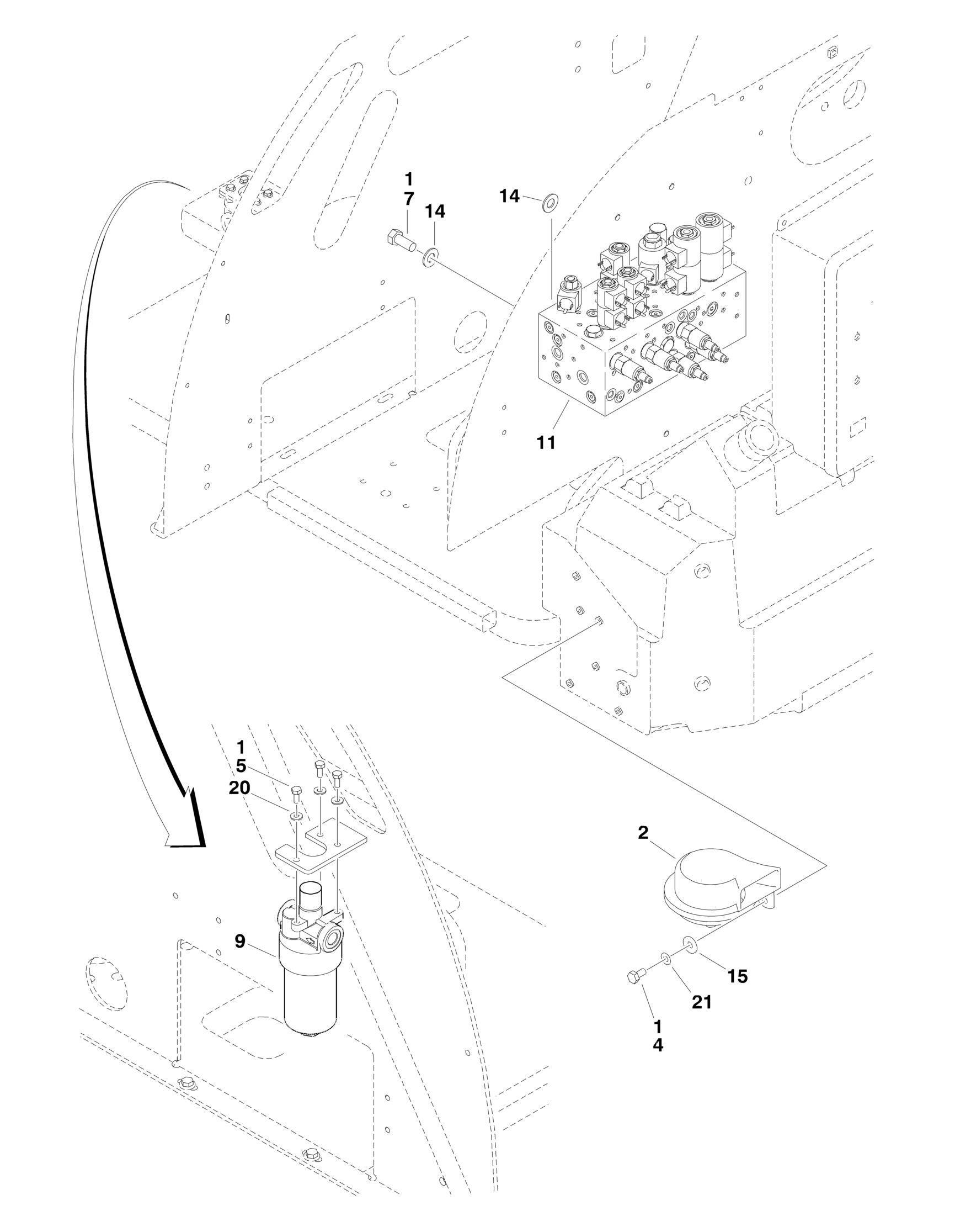
FIGURE 2-1. CONTROL VALVE INSTALLATION
FIGURE 2-1. CONTROL VALVE INSTALLATION
FIGURE 2-1. CONTROL VALVE INSTALLATION
ITEM PART NUMBER QTY
DESCRIPTION
Ref VALVES INSTALLATIONS 0271197 Ref Belgium Built Machines (Prior to SN 1300001243) 0274616 Ref Belgium Built Machines (SN 1300001243 to Present) 0274616 Ref Romanian Built Machines (SN E300000100 through
E300001114)
1 0100011 AR Compound, Locking 2 0140001 1 Horn 4 0641404 1 Bolt 1/4in-20NC x 1/2in 5 0651405 4 Bolt 1/4in-24NF x 5/8in 7 0641607 4 Bolt 3/8in-16NC x 7/8in 9 Ref Pressure Filter Assembly Options: 9 2120163 1 Belgium Built Machines (Prior to SN 1300001243) 9 2120150 1 Element, Filter 9 7020020 1 Indicator 9 7023206 1 O-Ring, Filter 9 7023207 1 Ring, Back-up 9 2120209 1 Belgium Built Machines (SN 1300001243 to Present) 9 2120209 1 Romanian Built Machines (SN E300000100 through
E300001114)
9 2120210 1 Element, Filter 9 7020020 1 Indicator 9 70000934 1 O-Ring, Filter Bowl 11 4641176 1 Main Control Valve Assembly (See MAIN CONTROL VALVE ASSEMBLY for Breakdown) 14 4711600 10 Flatwasher 3/8in Thin 15 4751400 1 Flatwasher 1/4in Regular 20 4711400 4 Flatwasher 1/4in Thin 21 4791400 1 Starwasher 1/4in
REV
F A A


