1 minute read
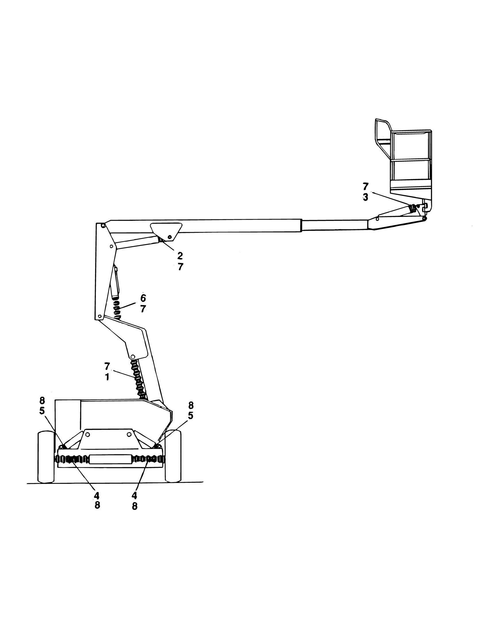
FIGURE 5-9. CLYINDER BELLOWS INSTALLATION (OPTIONAL


ITEM PART NUMBER QTY
DESCRIPTION
Ref BELLOWS INSTALLATIONS 0250862 Ref 2WD MACHINES WITH FIXED AXLE 0256324 Ref 2WD/4WS MACHINES WITH FIXED AXLE (SN 23615 to
Present)
0250863 Ref 2WD MACHINES WITH OSCILLATING AXLE 0256326 Ref 2WD/4WS MACHINES WITH OSCILLATING AXLE (SN 23615 to
Present)
0250864 Ref 4WD MACHINES WITH FIXED AXLE 0256325 Ref 4WD/4WS MACHINES WITH FIXED AXLE (SN 23615 to
Present)
0250865 Ref 4WD MACHINES WITH OSCILLATING AXLE 0256327 Ref 4WD/4WS MACHINES WITH OSCILLATING AXLE (SN 23615 to
Present)
1 0460092 1 Bellows (With Zipper) (Tower Lift Cylinder) 2 0460093 1 Bellows (With Zipper) (Main Lift Cylinder) 3 0460084 1 Bellows (With Zipper) (Platform Level Cylinder) 4 Ref Bellows (With Zipper) (Steer Cylinder) Options: 4 0460073 1 2WD 4 0460075 1 4WD 4 0460075 1 4WS 5 Ref Bellows (With Zipper) (Lockout Cylinder) Options: 5 Not Required 2 2WD Machines With Fixed Axle 5 0460083 2 2WD Machines With Oscillating Axle 6 0460099 1 Bellows (With Zipper) (Upright Level Cylinder) 7 1320122 4 Clamp, Worm Gear (5 1/8in-6in Dia) 8 1320037 Ref Clamp, Worm Gear (3in-5 1/8in Dia) 8 1320037 1 2WD/4WD Machines With Fixed Axle 8 1320037 3 2WD/4WD Machines With Oscillating Axle
REV
F
F
F
F


