28 minute read
CHAPTER 8. MAINTENANCE


What are explained hereunder are the maintenance items which you can cope with. When you encounter any abnormality or trouble which is not mentioned in this manual, please ask your dealer for service.
WARNING: When lubrication or servicing the Zero turn mower:
• Place it on level, hard ground.
• Stop the engine and remove the starter key.
• Depress the brake pedal and lock the parking brake securely.
• Shift the lift lever to down position ( ) to lower the mower deck onto the ground.
• Shift the PTO switch to the OFF position ( ).
• Service the Zero turn mower after the engine has cooled down sufficiently. With these items in mind, confirm the safety conditions for maintenance operation without fail ahead of time.
Service access
Opening / Closing hood
To release the hood, move the open/close level1, in the direction shown by the arrow.
Open the hood by grasping and lifting up the front of the food.
Folding seat and suspension forward
To fold seat and suspension forward, remove the bolts, 2, and then grasp the backrest of the seat and fold seat and suspension forward.
NOTE: In case of folding the seat only forward, firstly move the plate,3, rearward. Then grasp the backrest of the seat and fold the seat forward.
1. ENGINE OIL LEVEL
a. Draw out the engine oil level gauge (dipstick),1, which is located on the right sidewall of the engine.
b. Wipe the end of the dipstick with dry cloth.
c. Then insert it into the engine properly.
d. Draw it again. Make sure that the oil level is between the upper and lower limits.
e. If the level is lower than the lower limit, replenish through the engine oil filler,2, to the upper limit with the same kind of oil as that in the engine.
CAUTION: Stop the engine and wait around 5 minutes at least before checking the oil level. Engine oil is so hot just after operation as to cause burns and it takes some time as well for all the oil to return to the oil pan.
IMPORTANT
• Never replenish with a different kind of oil. The addition of different kind of oil will deteriorate the quality of the original oil.
• The oil level should not exceed the upper limit. Excessive oil will cause engine trouble.
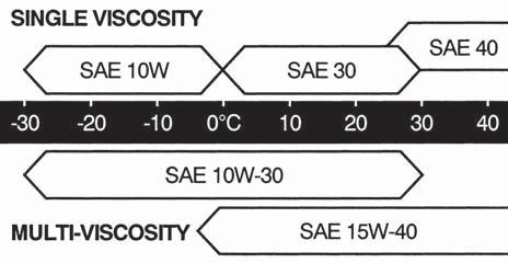
• Use oil of the quality recommended by ISEKI or 10W30 CC grade of SAE classification or higher quality.
• Use oil of proper viscosity in accordance with the atmospheric temperature.
• The oil level should not exceed the upper limit. Excessive oil can lead to engine overheating.
2. HST OIL LEVEL
a. You can make access to the HST oil level gauge (dipstick),2, on the HST oil tank,1, by open the hood.
b. Remove the HST oil filler,2.
c. Wipe the tip with dry cloth.
d. Insert the dipstick into the gauge insert completely.
e. Remove it again. Make sure that the level is between the upper and lower limits.
f. When the oil level is lower than the lower limit, replenish with fresh hydrostatic oil up to the level between the upper and lower limits.
IMPORTANT: The HST oil is common with oil for the hydrostatic transmission (HST) and the hydraulic lift cylinder, so pay sufficient attention not to allow dust, water, and other foreign matter to be trapped in the oil.
WARNING: Never remove the radiator cap during or just after operation. The water in the radiator is very hot and highly pressurized, so it may cause burns. Allow the engine to cool down sufficiently before inspecting coolant level.
a. Open the engine hood.
b. Make sure that the coolant level in the reserve tank is between the upper and lower limits. If the level is lower than the lower limit, replenish the reserve tank,1, with fresh clean soft water.
CAUTION: Tighten the radiator cap securely, or hot water may gush out through the cap, which is very dangerous.
Check to see the fuel level with the fuel gauge,1, on the control panel,2.
The letter "F" shows the upper limit. The letter "E" shows the lower limit.
Fuel replenishment should be done before operation if required.
Fuel capacity: 36 litres (7.92 imp. gal.)
DANGER: When replenishing fuel, abide by the following items, or a fire may be caused.
• Before replenishing with fuel, be sure to stop the engine and wait until the engine and heated parts cool down sufficiently.
• Keep sparks, open flames, etc. away from the fuel tank.
• No smoking!
• Spilt fuel should be wiped away immediately
IMPORTANT: • As soon as the fuel gauge shows "E", replenish with fuel. Never attempt to keep on operating with oil level lower than E, or air may be trapped in the fuel system, which will cause hard engine starting and poor engine power.
• Use diesel fuel. Never use heavy oil or gasoline (petrol). Use of fuel other than diesel fuel will cause fuel injection pump trouble.
5. AIR-CLEANER
a. The air-cleaner,1, is held on the engine with the rubber band. Untie this band and pick up the air-cleaner by hand.
b. Pinch the vacuum valve,1, to eject the dust accumulated inside. When the dust is wet, wipe it off with dry cloth.
c. Draw the element,2, out of the air-cleaner.
d. Dust it off by patting lightly while holding it with the other hand.
e. When the element does not become clean only by patting, blow dust off the element with compressed air. Apply compressed air from inside to outside of the element.
f. When the element does not become sufficiently clean only by blowing, dip it in neutral detergent solution for about 30 minutes and then rinse it in fresh water. Then dry it in the atmospheric temperature.
g. After cleaning install the element in reverse order of disassembly.
IMPORTANT:
• Never hit the element against a hard object like a concrete wall.
• An element which has already been washed five times or is damaged should be replaced with a new one.
• Never attempt to start the engine without the air-cleaner element. Such operation will cause engine trouble.
6. FUEL STRAINER
The fuel strainer is located between the left side rear tire and engine. Check the strainer for accumulated dust or water in the bottom of the strainer cup.
a. When dust or water is found accumulated in the bottom, turn the fuel cock lever by 180 degrees towards the bolt to stop fuel flowing.
b. Remove the ring nut to remove the strainer cup and element.
c. Wash the inside of the strainer cup and element in diesel fuel.
DANGER:
• Smoking is prohibited when the fuel strainer is being cleaned or inspected.
• Keep away sparks and open flames from the strainer.
• Split fuel should be wiped away immediately.
IMPORTANT:
• Be sure to install the O-ring when re-installing the strainer.
• When the fuel tank is emptied and air is trapped in the fuel system, bleed the air as follows:
1. Fill the fuel tank.
2. Turn the fuel cook to "Open" position.
3. Loosen the air-bleeding screw and let air bubbles out.
7. INSPECTION OF FUEL HOSES
Check the fuel hoses for cracks and fuel leak after every 100 hours of operation. A damaged hose should be replaced with a new one.
(2)
WARNING:
• Before checking the fan belt, stop the engine and remove the starter key without fail.
• Wait until the engine and accessories cool down completely to prevent burns.
The fan belt is accessible from the right rear of the engine room by. opening the engine hood. Check the belt for tension and damage.
Push down the belt with a finger at the intermediate point between the alternator and crankshaft pulley with a force of 10 kgf (22 lb) and see its deflection. If it deflects by about 10 mm (0.4 in.), the tension is proper.
When the belt deflection is improper, correct in the following procedure: a. Loosen the lock nut and adjust bolt of the alternator. b. Pull the alternator outward to apply more tension to the belt. Tighten the lock bolt and adjust bolt temporarily while pulling the alternator. c. Check for the belt deflection to see if the tension is proper. If so, tighten the lock nut and adjust bolt securely.
IMPORTANT: When the belt is found to be defective, ask your dealer for replacement.
9. ADJUSTMENT OF BRAKE
a. Step on the brake pedal,1, located on the right of the step to its limit. Then, adjust the adjust bolt so that the notch of the parking lever,2, locks at the third level.
b. Adjust the brake rod,4, with the parking brake so that the space between the coils of the pair of brake springs,5, is set to 0.9 mm (0.35 in).
c. Start the engine and drive the zero-turn mower forward at a low speed. Step on the brakes and check if the brakes are working evenly or not.
d. Stop the engine and make sure to lock the lock nuts,6, of the brake rod.
DANGER: Please make sure that the engine is turned off before adjusting the brakes.
10. ADJUSTMENT NEUTRAL OF HST CONTROL LEVER
a. Adjust the HST adjust rod,3, to the neutral position of the HST pump ASSY at which the drive control lever,1, can swing outwards.
b. Please consult your dealer if the neutral position of the HST pump ASSY cannot be set properly.
DANGER: Please make sure that the engine is turned off before adjusting the HST adjust rod.
11. ADJUSTMENT OF STRAIGHT DRIVE
Please perform the following steps when the zero-turn mower tends to curve to the left or to the right when both levers are depressed to their maximum.
a. Remove the boots of the drive control lever at the side to which the mower tends to curve.
b. Slightly tighten the adjust bolt,1, at the side to which the mower tends to curve by tightening the lock nut.
c. Start the engine and drive forward to check how much the zero-turn mower curves.
d. The curvature should be no more than 3 meters after traveling for 20 meters.
e. When the curvature is within the limit prescribed above, stop the engine and re-install the boots to its original position.
DANGER: Please make sure that the engine is turned off before adjusting the adjust bolt to adjust straight drive performance.
(1) Drive control lever (3) HST adjust rod
(2) Rod end
(1) Adjust bolts
12. ADJUSTMENT PHASE OF DRIVE CONTROL LEVER
After adjusting the straight drive operation of the mower, perform the following steps when the amount of depression of the left and right control levers are not the same.
a. Remove the boots,3, of both drive control levers,1.
b. Loosen the adjust bolts,2, and adjust the depression of both drive control levers.
c. Re-install the boots to their original position.
DANGER: Please make sure that the engine is turned off before adjusting the depression of the control levers using the adjust bolt.
(1) Drive control levers
(2) Adjust bolts
(3) Boots
13. ADJUSTMENT CLEARANCE OF DRIVE CONTROL LEVER
a. Remove the boots of both drive control levers.
b. Loosen the adjust bolts,3, to adjust the adjust plate.
c. Adjust the control levers so that their clearance is about 35 mm (1.38 in). Tighten the adjust bolts.
d. Re-install the boots to their original position.
DANGER: Please make sure that the engine is turned off before adjusting the adjust bolts.
Insufficient clearance in both left and right control levers can lead to abnormal operation of the zero-turn mower. Therefore, the clearance limit prescribed above should be maintained.
14. INSPECTION OF WHEEL TIGHTEN ING BOLTS AND NUTS
Check the wheel tightening bolts and nuts for looseness. All loose bolts should be tightened to the specified level.
Specified tightening torque:
Rear wheel: 64.3~75.9 ft-lbs (87.2~102.9 N.m)
(1) Drive control lever L.H. (3) Adjust bolts
(2) Drive control lever R.H. (4) Adjust plate
DANGER:
・ The battery generates very explosive gasses, so avoid smoking and keep sparks and open flames away from the battery. Charging the battery should be done in a place well ventilated to disperse explosive gasses as quickly as possible.
・ Battery electrolyte is very corrosive and will cause burns, so if it splashes on skin or clothes, wash it off immediately. If acid contacts eyes, flush immediately with clean water and get medical attention.
・When using booster cables, take sufficient safety measures.
■ INSPECTION OF BATTERY
The battery,1, is located between the engine and right rear wheel.
Battery indicator (1) with colors shows battery condition. When checking battery, park machine in a horizontal place and check the indicator at top of battery.
If indicator shows clear or light green color, tap battery body to remove bubble inside indicator.
■ HANDLING OF THE BATTERY
WARNING: a. As atmospheric temperature lowers, the performance of the battery also lowers. Consequently the battery should be serviced with special care in wintertime. b. As the battery discharges even when it is not used, it should be charged every month or every other month at the maximum. c. When the Zero turn mower is not used for a long time, remove the battery from the Zero turn mower and store it in a place dry and shaded from direct sunshine.
・ Be sure to connect the battery terminals correctly.
・The wiring from the battery should be kept clean and connectors tight. Dirty or loose wiring may cause a fire.
・When disconnecting the battery, disconnect the negative terminal first and vice versa when connecting.
・ When replacing the battery, use a battery of the same capacity as that of the current one (55B24R).
IMPORTANT: Quick charging should be avoided, for it will shorten the service life of the battery.
IMPORTANT: When storing Zero turn mower for long period without operation, self-discharge of battery will happen (especially in winter). If the Zero turn mower is stored for more than 1 month, the battery minus terminal should be disconnected. When operating for the first time or after long term storage, check if the battery charge level is enough. (If measurement of battery voltage is available, check if the voltage is more than 12.5V.) When the Zero turn mower is stored more than 6 months, charge the battery.
NOTE: Do not throw away the battery to the garbage can. Recycle it to follow the law of your community.
16. TYRE PRESSURE (INFLATION)
Improper tyre pressure causes the tyres to wear abnormally and affects the Zero turn mower performance. Too high pressure causes the Zero turn mower to bounce too much and too low pressure increases travelling resistance, which leads to power loss.
Tyre pressure should be checked every day.
WARNING:
• Tyre inflation should be set to the values specified in this manual. Excessive inflation may cause certain types to explode, which may result in serious accidents.
• Never use a tyre with a cut or crack which reaches tyre cords as such a tyre may explode.
• When a tyre, tube, or rim is required for replacement, ask your dealer. Such operation should be done by a mechanic trained especially for tyre handling.
• Insufficient pressure in the tires causes uneven tire friction that can shorten tire lifetime.
17. ENGINE OIL REPLACEMENT
IMPORTANT: a. Place a tray or the like under the oil drain to receive drained oil. b. The engine should be warmed up for 10 minutes or so ahead of time to heat the oil to lower its viscosity for compete drainage. c. Remove the drain plug, 2, allowing the used oil drain out completely. d. When the used oil has drained out completely, screw the drain plug back in securely. e. Remove the oil filler cap, 3, from top of the cylinder head cover, 4, and pour in fresh engine oil through the oil filler. Be sure to use oil recommended by ISEKI. Refer to " 1. ENGINE OIL LEVEL ".
• The engine oil should be replaced with fresh oil in accordance with operation hours. If not, overly used oil will cause engine troubles.
• The first replacement should be done after the initial 50 hours of operation and then after every 150 hours of operation.
When replacing engine oil, place the Zero turn mower on level, hard ground.
The engine oil drain is located bottom of the engine oil pan, 1, which is accessible from the left side of the Zero turn mower.
Engine oil capacity: 4.5 litres (0.99 imp.gal) f. After engine oil replacement, start the engine and let it idle for a while. g. Then stop it and wait for a while until the engine oil comes down into the oil pan. Now check the oil level to check to see if it is at the upper limit or not. When the level is low, replenish until the level reaches the upper limit. h. Make sure that there is no oil leakage through the drain plug and oil filter.
IMPORTANT: Never fill over the upper limit, or it may cause engine trouble.
18. ENGINE OIL FILTER REPLACEMENT
IMPORTANT: a. Drain engine oil completely following the instructions of "17. ENGINE OIL REPLACEMENT." b. Place some rags under the engine oil filter to receive dripping oil when the filter is replaced. The engine oil filter is located on the Left-hand wall of the cylinder block. c. Loosen the filter using a filter spanner and remove it. d. Install a new filter with the O-ring lubricated with fresh engine oil. Screw in the filter until its packing comes into contact with the sealing surface of the engine and then tighten it by a 2/3 turn with the filter spanner. e. Pour the drained oil back in referring to ’’17 ENGINE OIL REPLACEMENT."
• The engine oil filter should be replaced after the initial 50 hours of operation and then after every 300 hours of operation.
• It is recommended to ask your dealer to replace the engine oil filter, because this operation requires a special tool. But when there is no alternative but to replace the filter by yourself, observe following instructions.
19. REAR AXLE GEAR OIL REPLACEMENT
IMPORTANT: a. Remove the bolt for the oil level hole,2. b. Remove the drain plug,1, allowing the used oil drain out completely. c. When the used oil has drained out completely, screw the drain plug back in securely. d. Pour in fresh oil through the oil level hole,2, until oil overflow from the hole. e. Screw the bolt for oil level hole.
• The transmission oil should be replaced after the initial 50 hours of operation and then after every 600 hours of operation.
Oil: Gear oil (SAE80)
20. REPLACEMENT OF HYDRAULIC OIL SUCTION FILTER
IMPORTANT: a. Remove the bolts of the seat base and then turn the seat. b. After the HST oil has drained out from the drain plugs,1&2, completely, remove the filter using the filter spanner. When removing the filter, a small amount of oil may spill, so place waste cloth under the filter to receive spilt oil. c. Apply thin coat of oil to the O-ring of the new oil filter cartridge ahead of time. Then install the filter. Screw in the filter by hand until the rubber packing comes into contact with the sealing surface, and then screw in it by a 2/3 turn with the filter spanner.
• The hydraulic oil filter should be replaced after the initial 50 hours of operation and then after every 300 hours of operation. It should also change every time the HST tank oil is replaced.
• It is recommended to ask your dealer to replace the hydraulic oil filter. But when there is no alternative but to replace the filter by yourself, observe the following instructions.
The hydraulic oil suction filter,3, is located front of the HST pump case under the seat.
Oil: Hydrostatic oil (ISO VG46)
21. INSPECTION AND CLEANING OF AIR-INTAKE OPENINGS
IMPORTANT:
• Air- Intake openings clogged with dust or dirt causes overheating of the engine due to deteriorated cooling efficiency of the radiator. The radiator and radiator screen should be checked for clogging everyday before operation.
• When mowing dead grass or operating under extremely dusty conditions, check the air-in-take openings several times a day to avoid clogging.
22. CLEANING OF THE RADIATOR
IMPORTANT: a. Draw out the radiator screen upwards. b. Dust off the radiator screen with a soft brush. c. The clogged radiator fins should be cleaned by applying compressed air or water from both sides alternatively. d. Re-install the radiator screen.
• The radiator screen and radiator clogged with dust or dirt causes overheating of the engine due to deteriorated cooling efficiency of the radiator. The radiator and radiator screen should be checked for clogging every day before operation.
• When mowing dead grass or operating under extremely dusty conditions, check the radiator screen and radiator several times a day to avoid clogging.
The radiator is located behind the engine and the radiator screen is located behind the radiator.
IMPORTANT:
• Avoid using excessively compressed air or water, which may deform the cooling fan blades.
• Avoid applying water directly to the wiring and electric apparatus.
• After washing the radiator using water from a tap, let it dry by itself.
23. COOLANT REPLACEMENT
WARNING: Never attempt to remove the radiator cap during or just after operation, or pressurized vapor and hot water will gush out, which may cause burns. So wait until the engine cools down sufficiently.
The drain plug of the engine coolant is located under the reserve tank of the left side of the engine.
a. Place a coolant receiver under the drain plug.
b. Remove the radiator cap and the drain plug to let all coolant drain out of the radiator and engine cylinder block.
c. When all coolant completely drained out, wash the inside of the radiator and tighten the drain plug securely.
d. Pour the coolant which has a specified antifreeze concentration until it starts overflowing through the coolant filler. Retighten the radiator cap securely.
WARNING: Be sure to tighten the radiator cap securely, or boiling coolant may shoot out, which is very dangerous.
IMPORTANT: e. After filling, start the engine and let it idle for 5 minutes or so. Then check the coolant level. If the level is low, replenish the reserve tank with coolant.
• Frozen coolant may damage the engine.
• Mixing ratio of water and antifreeze is different by antifreeze manufacturers and atmospheric temperatures.
• Water and antifreeze should be blended sufficiently ahead of time.
IMPORTANT:
• Never attempt to run the engine without coolant, or the engine will seize, leading to its complete damage.
24. INSPECTION OF FUSES AND WIRING
The fuse box is located in the right hand side inside the engine room of the Zero turn mower.
CAUTION:
• The 20A fuse in fuse box is not a spars fuse. It is installed to provide power to the electric system of an implement other than the mower Never use it in place of the other fuses.
• Never replace blown fuses or slow-blow fuse with wire.
IMPORTANT:
• When a fuse or a slow-blow fuse is blown, be sure to locate the trouble and correct it. When the cause is not clear, consult your dealers.
• Be sure to use specified fuses. Larger-capacity fuses will cause burn-out of electric accessories and wiring.
• When a slow-blow fuse has been burnt out, use genuine slow-blow fuse
The alternator and the starter motor have their own slow-blow fuse.
WARNING:
• Damaged wire covers should be mended with insulation tape immediately.
CAUTION:
• The wiring of the Zero turn mower should be checked every year at your dealers to avoid electrical fires.
• Grass and dust around the battery, wiring, muffler and engine should be removed. Otherwise they may catch fire.
IMPORTANT:
• When a wire harness has come off its clamp, it should be re-clamped immediately.
25.
Maintenance Of Hydraulic System Parts
When hydraulic system parts such as the HST unit, hydraulic pump, control valve, hydraulic cylinder, piping, etc. are required to be adjusted or repaired, consult your ISEKI dealers. Users are advised not to adjust or repair hydraulic system parts by themselves.
26.
Inspection Of Safety Switches
Safety devices are installed for safe operation. Make certain that each device works properly before operation following the next procedures.
CAUTION: When the engine does not start due to a defective safety switch or does not stop even when the operator leaves his seat, ask your dealer for repair immediately.
INSPECTION 1 a. Be seated in the operator's seat. b. Turn the PTO switch to the ON ( ) position. c. Set the drive control lever to the neutral open-lock position. d. Depress the brake pedal. e. Turn the key switch to the START ( ) position. f. Make sure that the engine is not cranked.
INSPECTION 2 a. Be seated in the operator's seat. b. Shift the PTO lever to the OFF ( ) position. c. Set the drive control lever to the drive position. d. Depress the brake pedal. e. Turn the key switch to the START ( ) position. f. Make sure that the engine is not cranked
INSPECTION 3 a. Be seated in the operator's seat. b. Turn the PTO switch to the OFF ( ) position. c. Set the drive control lever to the neutral open-lock position. d. Don't depress the brake pedal. e. Turn the key switch to the START ( ) position. f. Make sure that the engine is not cranked.
INSPECTION 4 a. Be seated in the operator's seat. b. Turn the PTO switch to the OFF ( ) position. c. Set the drive control lever to the neutral open-lock position. d. Depress the brake pedal. e. Turn the key switch to the START ( ) position. f. Make sure that the engine is cranked and started. g. Apply the parking brakes. h. Leave from the operator's seat. i. Make sure that the engine working continue. j. Close the drive control lever and check if the buzzer sounds off. The engine should stop after 1 second.
INSPECTION 5 (ONLY FOR F-TYPE)
a. Be seated in the operator's seat.
b. Turn the PTO switch to the OFF ( ) position.
c. Set the drive control lever to the neutral open-lock position.
d. Depress the brake pedal.
e. Turn the key to the START ( ) position.
f. On this condition, make sure that it is not started the engine with the engine hood is open.
(imp.gal.)
Radiator Reserve tank
HST oil tank
Rear axle gear case (LH)
Rear axle gear case (RH)
Fuel tank
Engine
HST drive shaft
Drive lever link
Brake link
Brake pedal hub
Front axle center pivot
Drive counter link
Front tire yoke (LH)
Front tire yoke (RH)
Mower lift link
Front tire hub (LH)
Front tire hub (RH)
Fresh clean water and LLC (50%)
Hydraulic oil (ISO VG46)
Gear oil (SAE80)
Gear oil (SAE80)
Diesel fuel Engine oil Grease Grease
As required
As required
As required
As required
As required
As required
As required
As required
As required
As required
As required
• Use oil of better than class CC. • Use ISEKI's recommended oil.
Periodical Inspection Table
: Inspect, replenish or adjust : Replace : Clean or wash : Replacement or servicing at authorized service facility recommended.
Above mentioned service intervals are for normal usage. If working conditions are harder, earlier service is recommended.
• If special skill or special tool are required or you feel difficulty in maintenance, consult your dealer
Washing The Machine
CAUTION: If you use high pressure washer, be sure to use in accordance with operator’s manual and safety label of washer. In case of irregular using. It may cause that personal injury and damaging of machine.
CAUTION: Set the nozzle of hose ‘spread’ and keep the distance more than 60cm in order to avoid damaging of machine. Especially, be care for not to hit the water to electrical parts and label.
Unsuitable washing may cause that
1. Fire by short circuit and damaging of electrical parts.
2. Flowing of oil by damaging of hydraulic hose.
3. Damaging and accident of machine.
(1) Coming off of label.
(2) Accident of electrical parts, engine, radiator, and interior.
(3) Damaging of lubber parts (tyre, seal) and resin parts.
(4) Coming off of paint.
Set the spaying nozzle in ‘spread’ position
Refparts Nameparts Code
1AIR CLEANERELEMENT ASSY1650-104-203-10
2FUEL FILTER ASSY1716-105-200-10
3ENGINE OIL FILTER CARTRIDGE6213-240-002-20
4FUSE BLADE 32V03A1575-623-009-00
5FUSE BLADE 32V10A1575-623-010-00
6FUSE BLADE 32V20A1593-623-203-00
7SLOW BLOW FUSE 40A1650-650-222-00
8SLOW BLOW FUSE 50A1614-690-202-00
9HST SUCTION FILTER1752-202-571-10
10BULB/12V3.4W3650-270-214-00
11BLADE (SSM60)8654-306-006-10
12BLADE (SSM72)8655-306-003-10
CHAPTER 9. STORAGE
■ DAILY AND SHORT TERM STORAGE
a. Clean the Zero turn mower.
IMPORTANT: When washing the zero turn mower mower, avoid applying compressed water directly to the electric apparatus, oil and fuel fillers. Remove the starter key and cap the switch key hole to prevent short circuits.
b. Lower the mower deck on the ground.
CAUTION: A lifted up mower deck may go down unexpectedly if the lift lever is manipulated by children or unauthorised people, which may lead to serious accidents.
c. The zero turn mower should be stored indoors if possible. When it has to be left outdoors, cover it with tarpaulin or the like.
WARNING: When it has to be left outdoors, cover it with tarpaulin after heated components such as the engine, muffler, etc. have cooled down completely. Otherwise a fire may be caused.
d. When the ambient temperature is very low, remove the battery and store it in a warm shaded dry place. This will contribute greatly to easy starting of the engine the following morning.
CAUTION: Remove the starter key without fail before storage.
■ LONG TERM STORAGE
a. Clean the zero turn mower and correct all troubles such as repair, replacement of defective parts, readjustment, etc.
b. Top up the fuel tank and close the fuel cock.
c. Replace the engine oil with new and let the engine idle for about 5 minutes to lubricate every part sufficiently.
d. Lubricate all lubrication points.
e. Grease up all greasing points.
f. Check bolts and nuts for looseness and re-tighten loose ones.
g. Inflate each tyre a little higher than specified.
h. Dismount the mower deck or lower it to the ground.
CAUTION: A lifted up mower deck may go down unexpectedly if the lift lever is manipulated children or unauthorised people, which may lead to serious accidents.
i. Cover the zero turn mower with tarpaulin or the like in order to protect it from rainfall and dust.
WARNING: When covering the zero turn mower with tarpaulin, wait until heated components such as the engine, muffler, etc. have cooled down completely. Otherwise a fire may be caused.
j. Remove the battery, charge it, and store it in a shaded dry place with no access to children.
k. Charge the battery completely every month.
CAUTION: Remove the starter key without fail before storage.
■ OPERATION AFTER A LONG TIME OF STORAGE
a. Perform the pre-operation inspection without fail.
b. Let the engine idle for about 30 minutes before applying any load, to ensure maximum engine performance and service life.
WARNING: Provide sufficient ventilation for exhaust fumes when starting the engine, because such fumes are very poisonous.
1. ENGINE
CHAPTER 10. TROUBLESHOOTING
Troubles
・ Starter motor does not work.
Presumable causes
・ Drive control lever is not open lock position.
・ Brake pedal is not depressed.
・ PTO switch is not in OFF ( ) position.
・ Battery is not charged fully.
・ Battery terminals are poorly connected.
・ Defective internal wiring in connector
・ Broken starter switch
・ Broken starter motor108
・ Open the engine hood
・ Starter motor works but engine does not start.
・ Cock of fuel strainer is closed.
・ No fuel
・ Water trapped in fuel
・ Air trapped in fuel
・ Clogged fuel hoses
・ Clogged fuel strainer
・ Slow cranking speed
・ Insufficient pre-heating
・ Throttle lever is in low ( ) speed position.
・ Too high engine oil viscosity
・ Clogged air-cleaner
・ Insufficient compression
・ Incorrect injection timing
・ Clogged injection nozzles
・ Engine runs at irregular speeds or stalls soon.
・ Air trapped in fuel system
・ Improper earthing
・ Clogged fuel strainer
・ Leaking fuel system
・ Defective injection pump
・ Engine knocks.
・ Too low engine oil level
・ Engine is overheated.
・ Coolant temperature does not rise.
・ Defective injection pump
Remedies
・ Shift it to neutral position.
・ Depress the brake pedal.
・ Turn it to OFF position.
・ Charge it.
・ Clean the terminal posts and connect them securely.
・ Rewire.
・ Consult your dealer.
・ Consult your dealer.
・ Close the engine hood securely.
・ Open it.
・ Replenish with fuel.
・ Drain trapped water from fuel strainer.
・ Bleed injection pump.
・ Clean fuel hose inside.
・ Wash or replace it.
・ Charge battery.
・ Preheat for specified time.
・ Shift it to high speed position.
・ Replace it with one of lower viscosity.
・ Clean element.
・ Consult your dealer.
・ Consult your dealer.
・ Consult your dealer.
・ Locate cause of airtrapping and bleed system of air.
・ Polish earthing points and re-connect.
・ Clean or replace it.
・ Tighten joints securely or replace damaged hose.
・ Consult your dealer.
・ Add oil to upper limit.
・ Consult your dealer.
・ Consult your dealer.
・ Consult your dealer.
Troubles
・ Engine knocks.
・ Engine output is insufficient.
Presumable causes
・ Defective injection nozzles
・ Incorrect valve clearances
・ No fuel
・ Clogged air cleaner
・ Engine is overloaded.
・ Improper fuel
・ Engine is overheated.
・ Throttle lever is not in the high speed ( ) position.
・ Insufficient compression
・ Improper valve clearances
・ Defective injection pump
・ Defective injection nozzles
・ Incorrect injection timing
・ Engine is overheated.
・ Low engine coolant level
・ Loose fan belt
・ Clogged radiator fins and screen
・ Too much engine oil
・ Clogged air-intake openings
・ Engine is overloaded.
・ Clogged engine oil filter
・ Burnt out coolant temperature warning lamp
Remedies
・ Consult your dealers.
・ Consult your dealers.
・ Supply with fuel.
・ Clean element.
・ Raise cutting height or slow down Zero turn mower.
・ Use proper diesel fuel.
・ Cool down engine.
・ Shift it there securely.
・ Consult your dealers.
・ Consult your dealers.
・ Consult your dealers.
・ Consult your dealers.
・ Consult your dealers.
・ Replenish
・ Tighten it properly.
・ Clean them.
・ Reduce the amount of engine oil up to the level gauge limit
・ Clean air-intake.
・ Raise cutting height or slow down Zero turn mower.
・ Ask your dealer to replace it with a new one.
・ Consult your dealers.
・ Oil pressure lamp is blinking
・ Low engine oil level
・ Low engine oil viscosity
・ Clogged engine oil filter
・ Defective oil pump
・ Defective oil pressure switch
・ Add oil to upper limit.
・ Replace with oil of higher viscosity.
・ Ask your dealer to replace it with a new one.
・ Consult your dealers.
・ Consult your dealers.
・ Exhaust fumes are white.
・ Clogged air cleaner
・ Too high engine oil level
・ Insufficient fuel injection
・ Clean element.
・ Drain oil to upper limit.
・ Consult your dealers.
・ Exhaust fumes are black.
・ Defective
・ Clogged intake system
・ Use proper fuel.
・ Clean air cleaner element.
Troubles
・ Exhaust fumes are black.
Presumable causes Remedies
・ Clogged exhaust system
・ Excessive fuel injection rate
・ Injection nozzle pressure
・ Incorrect injection timing
・ Check muffler for clogging and clean it.
・ Consult your dealers.
・ Consult your dealers.
・ Consult your dealers.
・ Engine stalls at low speed.
・ Defective injection pump
・ Defective injection nozzles
・ Incorrect valve clearance
・ Consult your dealers.
・ Consult your dealers.
・ Consult your dealers.
・ Engine races.
・ Excessive fuel consumption
・ Clogged governor
・ Engine oil leaks into cylinder.
・ Defective fuel
・ Clogged air-intake line
・ Engine is overloaded.
・ Fuel leaks
・ Incorrect valve clearances
・ Consult your dealers.
・ Consult your dealers.
・ Use proper fuel.
・ Clean air cleaner and air-intake hose inside.
・ Raise cutting height or slow down Zero turn mower.
・ Replace damaged parts with new ones and tighten joints securely.
・ Consult your dealers.
・ Charge lamp is blinking.
・ Defective wiring
・ Loose fan belt
・ Defective alternator
2. BRAKE SYSTEM
・ Defective braking effect or uneven braking
・ Brake pedal does not return smoothly.
3. LIFT SYSTEM
・ Lift does not rise.
・ Excessive master brake pedal play
・ Worn brake shoes
・ Fatigued or broken return spring
・ Defective lubrication of linkage
・ Correct loose, dirty, short, improperly earthed terminals.
・ Tighten it properly.
・ Consult your dealers.
・ Correct pedal play.
・ Consult your dealers.
・ Replace it.
・ Lubricate lubrication points.
・ Low HST oil tank level
・ Air trapped inside hydraulic piping
・ Fill up to upper limit.
・ Consult your dealers.
Troubles
・ Lift does not rise.
Presumable causes Remedies
・ Clogged HST oil suction filter
・ Defective hydraulic pump
・ Defective control valve
・ Defective hydraulic cylinder
・ Consult your dealers.
・ Consult your dealers.
・ Consult your dealers.
・ Consult your dealers.
・ Lift does not lower.
・ Defective control valve
・ Height adjust dial is not set in 1.0 inch.
4. DRIVE CONTROL SYSTEM
・ The maximum prescribed speed is not reached
・ Deterioration in the efficiency of the pump and motor
・ Faulty setting of the drive control lever linkage
・ Insufficient amount of HST oil
・ Consult your dealers.
・ Set in 1.0 inch.
・ Poor translator movement
・ Differences in the alignment of the lever pairs during translator movement
・ Imbalance in efficiencies of the pump and motor pairs
・ Faulty setting of the control lever linkage
5. HST (HYDROSTATIC TRANSMISSION)
・ Zero turn mower does not start travelling.
・ Parking brake is applied.
・ Too low engine speed
・ Low HST oil tank level
・ Air trapped inside hydraulic piping
・ Improperly adjusted the drive control lever
・ Clogged suction oil filter
・ Defective HST unit
・ Consult your dealer.
・ Adjust the setting by following the manual instructions.
・ Replenish the HST oil tank with the prescribed amount of oil.
・ Consult your dealer.
・ Adjust the setting by following the manual instructions.
・ Zero turn mower creeps without the drive control lever being operated
・ Faulty neutral setting of the drive control lever
・ Incorrect neutral point of HST
・ Improperly positioned neutral arm
・ Defective HST unit
・ Release it.
・ Accelerate engine.
・ Fill to upper limit.
・ Consult your dealers.
・ Consult your dealers.
・ Consult your dealers.
・ Consult your dealers.
・ Adjust the setting by following the manual instructions.
・ Consult your dealers.
・ Consult your dealers.
・ Consult your dealers.
6. ELECTRICAL ACCESSORIES
Troubles
・ Battery is not charged.
Presumable causes Remedies
・ Melted slow-blow fuse
・ Defective wiring
・ Loose fan belt
・ Defective battery
・ Defective alternator
・ Locate and repair cause of trouble, and install a new slow-blow fuse.
・ Check wiring for loose terminals and earth, and short circuit. Repair defective parts.
・ Tighten belt as specified.
・ Correct loose terminals and corroded parts, Otherwise, install a new battery.
・ Consult your dealers.
・ Monitor lamps do not light up.
・ Fuel pump does not work.
・ Defective contact
・ Re-connect connector.
・ Fuel cut-off solenoid does not work.
・ Blown fuse
・ Defective fuel pump
・ Blown fuse
・ Defective solenoid
・ Check the wiring and replace the blown fuse with a new one.
・ Consult your dealers.
・ Check the wiring and replace the blown fuse with a new one.
・ Consult your dealers.
CHAPTER 11. WIRING HARNESS CABLE
CHAPTER 1. NAME OF MAJOR COMPONENTS
SSM60 & SSM72 (SZ330)
(1) Drive shaft
(2) Roll pin
(3) Input shaft
(4) Bevel gear
(5) Cover case
(6) Output shaft
(7) Gear case
(8) Pulley
(9) Metal center
(10) Grease nipple
(11) Nut (M16)
(12) Pulley
(13) Shaft side
(14) Metal side
(15) Collar blade
(16) Blade
(17) Washer (20 x 60 x 06)
(18) S.W (M20)
(19) Nut (M20 x 1.5)
(20) Washer