15 minute read
PTO Operating Control (S-Type and HST-Type)


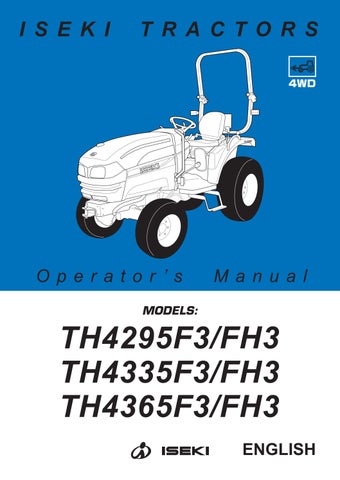
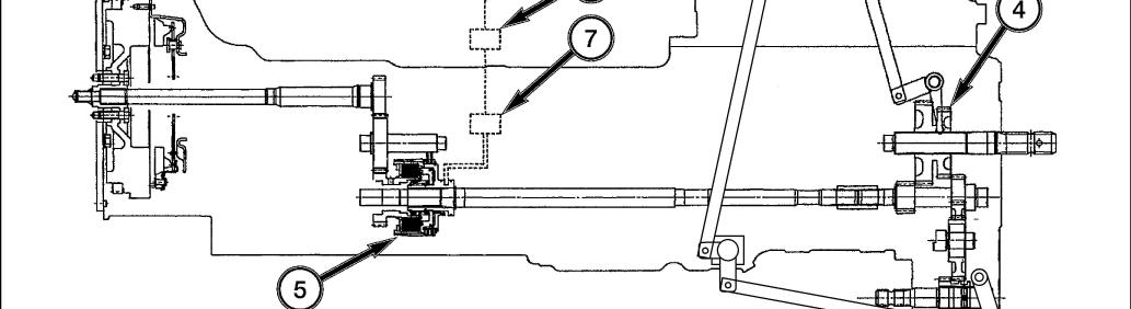
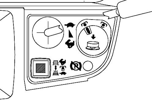
FIG. 103: To select rear PTO - Make sure PTO control switch is OFF and then move rear PTO selector lever (2) engage gear set (4) inside rear housing.
FIG. 103: To engage PTO - Turn PTO switch, clockwise and then pull up to actuate hydraulic clutch (5) and complete the drive. The indicator light in the warning light strip will come on, showing PTO clutch is engaged.
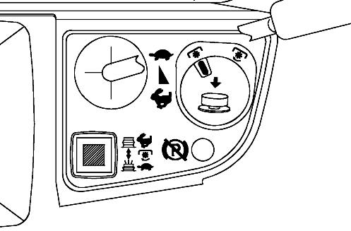
FIG. 103: To disengage PTO - Push PTO switch (1) to release hydraulic clutch (5).
When further use of rear PTO is not required, depress clutch pedal and return rear PTO selector lever (2) to neutral.
FIG. 105: To select mid PTO - Make sure PTO control switch is off and then move PTO selector lever (8) forward to mid PTO position to engage gear set in mid PTO.
NOTE: PTO can be engaged / disengaged by control switch (1) independently of main clutch. Reduce engine revolution speed prior to engaging (switching on) and disengaging (switching off) PTO. Always move PTO control switch to OFF before shifting rear or mid PTO selector levers. Rear and mid PTO can be operated separately or together.
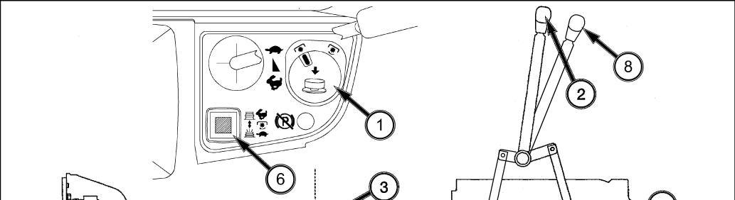
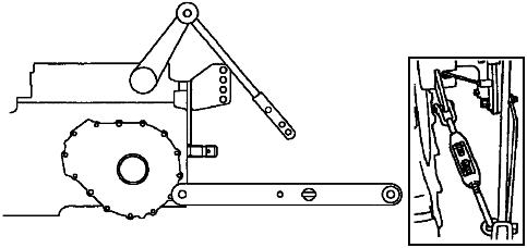
FIG. 106: The pressure control valve (7) operates when the PTO clutch (5) begins to operate, enabling efficient engaging of the PTO with a minimum of shock.
Setting the mode change switch (6) facilitates optimum engagement of the PTO.
Push PTO selectable switch (6) to engage rear and mid PTO more smoothly and slowly.
Push PTO selectable switch (6) again, to return to normal mode.
NOTE: Lower the engine speed when turning On PTO control switch if there is considerable shock.
SwitchSwitch lampRequired torque
Shock & noise at engage Attachment OFFOFFBigHighShortNormalRotary, Cultivator ONONSmallLowLongSmallerMower, Hayer
Initial pressure rise at engage speed of pressure rise
3-POINT HITCH
3-point hitch combines tractor and implement into 1 working unit. Implement position and raising are controlled hydraulically. In addition, implement weight and loads impose downward pressure at tractor rear wheels to increase traction.
Hitch Controls
FIG. 107: Control quadrant, to right of operator’s seat, controls the system to provide the following hitch control functions:
Position Control - Maintains hitch position at constant height in relation to the tractor. As position control lever (1) is moved rearward, hitch (and implement) are raised. Moving lever forward will lower hitch to selected position. Each lever setting provides a specific hitch (and implement) position.
Draft Control - Regulates hitch height to provide constant draft or “pull” of ground engaging implements (plows, subsoilers, etc.). Moving draft control lever (2) forward will provide deeper implements working depth. Moving lever backward will provide a shallower depth. As ground contours and / or soil conditions change, the system will raise or lower implements as needed to keep even load in tractor.
CAUTION: Use position control lever (1) when attaching or detaching implements. Place draft control lever (2) fully forward when using position control.
FIG. 108: Lowering Rate Control - Knob (3) controls discharge rate of hydraulic oil to adjust lowering speed of hitch and implement. Turn knob clockwise to slow drop rate, counterclockwise to increase drop rate. Turning knob fully clockwise will lock implement in raised position.
CAUTION: When working on or around mounted implements, always lower to ground prior to work. If implement must be raised, always block implement and lower links securely.
Rear Linkage
FIG. 109: Linkage consists of several major components for implement attachment and operation:
Lower Links (1) - Primary attaching points to lower implement pins.
Lift Rods (2) - Connect lower links to hydraulic lift arms for raising / lowering of lower links. The lift rod connected to the right lower link has provisions for leveling the implement (side to side).
Check Chain (3) - Reduce side away of implement.
Top Link (4) - Adjustable, turn-buckle type to level implement (front to rear). Top link also provides draft load sensing for draft control.
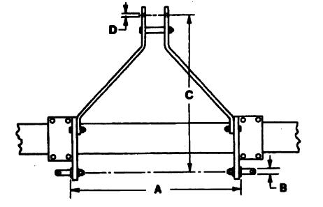
FIG. 110: To match varying implements, rear linkage is standardized according to spacing, pin size, etc. This enables usage of alternate implements with minimal adjustments as long as matching size or “Category” is used.
This tractor is equipped for “Category I” implements with following attaching point dimensions:
TABLE 6: Attaching point dimension
Ref.DescriptionDimension (Size)
ALower Link Width 681 mm (26.8”)
B Lower Link Pin Diameter 22 mm (0.88”) CTop Link Height 457 mm (18”)
DTop Link Pin Diameter 19 mm (0.75”)
FIG. 111: The linkage provides 2 positions of connecting the top link (1) to the tractor. For most implements, securing the top link, A, is satisfactory, but the position may be varied to provide increased implement height during transport.
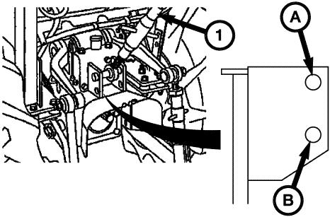
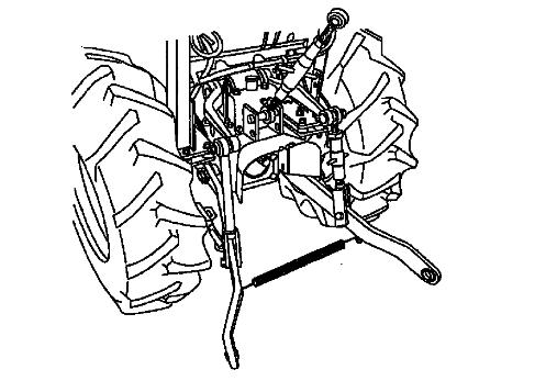
FIG. 112: Lift rods (1) and lower links (2) also have multiple positions. Normally, Center hole, A, in each lift rod is attached to forward hole, X, in lower link.
CAUTION: Secure all pins after adjustment is made. Always use pins supplied with tractor.
CAUTION: Stay clear from the area of the 3-point linkage when working mounted machine, trailers and towed machinery.
NOTE: When attaching implements to PTO shaft, adjust the height and width of 3-point to have clearance between implement and 3-point linkage. Also check any interference with the master shield.
Attaching Implements
CAUTION: Always use POSITION CONTROL to attach / detach implements to provide precise control of hitch.
FIG. 113: Back tractor to implement, centering tractor with implement hitch frame.

Raise or lower hitch using position control lever (1), and align left lower link end with corresponding implement attaching pin.

Lock the brakes, shut off engine and remove key.
FIG. 114: Slide ball end of left lower link (1) over implement pin and secure with linchpin.
Adjust height of right lower link using leveling turn buckle (2). Attach and secure right lower link (3) to implement with linchpin.
Attach top link (4) to top of implement hitch frame using pin supplied with tractor. Rotate center barrel section of top link, to lengthen or shorten it, and level implement from front to rear.
After the implement is attached, it can be readjusted for level operation using turn buckle and top link. Secure all adjustments.
IMPORTANT: With some mounted implements, it will be necessary to remove drawbar at rear of tractor to permit implement to be raised and lowered without obstruction.
FIG. 115: Certain implements require minimal sideplay. Check chain (1) at each lower link should be evenly adjusted to reduce side-play to desirable level. Do not remove all side-play as lower link damage may result.
NOTE: The amount of side-play (stabilizer looseness) is dependent upon implement and type of operation. Normally 50 mm (2”) of total side movement is desired, 25 mm (1”) to each side of tractor centerline.
Using Position Control
FIG. 116: Type of Work - Attaching / detaching implements and other operations requiring implement to be kept at constant height above ground. Also used with tool bars having flexible row units and implements equipped with gauge (support) wheels.
FIG. 117: Lever Positions - Use position control lever, 1, to adjust hitch and implement position.
NOTE: Front lever stopper (2) can be set to contact position control lever in implement work position. This enables implement to be returned to identical position after hitch has been raised for turning, transporting, etc. Rear lever stopper (3) can be set to limit raising height, if required.
To Begin Work - Align tractor and implement in field and move position control lever (1) forward (toward DOWN). Adjust implement height using position control lever and set adjustable stoppers (2) and (3) as desired.
When Turning - Move position lever (1) backward (toward UP) to raise implement. Finish turning and return lever against stopper to resume operation.
To Finish Work and Transport - Move position control lever (1) fully rearward in quadrant.
FIG. 118: Lowering speed can be readjusted as necessary using lowering rate control knob (4).
CAUTION: When using mounted implements with PTO driveline, make sure: PTO drive shaft has minimum 51 mm (2”) engagement of telescoping sections, at all hitch / implement positions.
Hitch height during raising does not bind drive shaft universal joints due to extreme drive shaft angles. Limiting raising height may be required.
PTO drive is disengaged during transport.
Using Draft Control (If equipped)
FIG. 119: Type of Work - When ground-engine implements such as plows, subsoilers, cultivators, etc. are used.
NOTE: Refer to “Rear Linkage” for locking pin details.
CAUTION: Do not use draft control when precise hitch positioning is required (attaching / detaching implements for example).
FIG. 120: Lever Positions - Use position control lever(1) to raise and lower implement and use draft control lever (2) to adjust implement working depth and system sensitivity in soil.
Position control lever (1) can also be used to prevent excessive lowering of hitch when low draft areas (sandy soil) are encountered.
NOTE: Adjust lever stoppers (3) and (4) can be set to contact position control lever in implement work or raised position. This enables implement to be returned to identical setting after hitch has been raised for turning at field ends.
To Begin Work - Align tractor and implement in field and move position control lever (1) forward (to DOWN). while driving tractor forward, lowering implement. Then adjust draft control lever (2) until correct working depth is maintained.
When Turning - Move position control lever (1) backward to raise implement and permit completion of turn. Return implement to work position by selecting position control lever to previous position against stopper.
To Finish Work and Transport - Pull position control lever backward fully to up setting.
FIG. 121: Lowering speed can be readjust as necessary with lowering rate control knob (5).
NOTE: Changes of soil texture or ground speed of unit may require slight readjustment of draft control lever to maintain consistent working depth as these can have a direct influence on implement draft load.
If erratic operation is encountered, turn lowering rate control knob (5) clockwise to slow. Lowering top link attaching location on tractor will also decrease sensitivity.
JOYSTICK OPERATION (J-TYPE)
FIG. 122: Single-lever control (1) provides “Joystick” operation of auxiliary valve. Moving lever backward and forward moves the 1+ / 1- spool in control valve respectively raising and lowering loader (or other attachment). Pushing lever completely forward will retain lever in “float” position to allow attachment to follow ground contours. Moving lever side-to-side moves the 2+ / 2- valve spool and controls Loader bucket position. Pulling lever to left will curl bucket and pushing lever to right will dump the bucket. Pushing lever completely to right side will retain lever in “regenerative” position, allowing bucket to dump quickly. When used with a blade angling (left and right) can be controlled. All positions (except float) will return to neutral position when lever is released. When in Float, the 1+ / 1valve spool is held by detents and the lever will have to be pulled rearward to disengage the detents.
NOTE: Inability to select “float” or any other valve functions may indicate the need for control rod adjustment at base of control lever.
NOTE: Other type than J-type can equip joystick as option.
Joystick Lockout
FIG. 123: The joystick has an lockout system. The joystick lockout (2) is a T-handle located near the joystick.
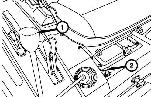
FIG. 124: To lock joystick, put T-handle in the down position. When the T-handle is in the down position, the joystick cannot be operated.
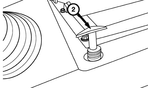
To unlock joystick, pull the T-handle up. When the Thandle is in the up position, the joystick can be operated.
NOTE: If the T-handle is not pulled all the way up, the T-handle will return to the down position and lock the joystick.
FIG. 125: Output ports are located under the right step.
1. The output ports are identified by letters, A, B, C, D, from left to right as indicated on output ports.
2. The following chart provides correct output port location when using a loader.
TABLE 7: Function of output port (loader)
Output PortFunction
A(1+)Loader Raise
B(1-)Loader Lower and Loader Float
C(2-)Bucket Curl
D(2+)Bucket Dump and Dump quickly
3. For other operations, except for loader work use the following.
TABLE 8: Function of output port (other operations)
Output PortDouble ActingSingle Acting
A(1+)ExtendExtend / Retract
B(1-)RetractNot Used
C(2-)ExtendNot Used
D(2+)RetractNot Used
External Auxiliary Hydraulics
Auxiliary hydraulics can be installed to operate implements requiring an external hydraulic source for operation. Kits are available as 1 spool valve (1 auxiliary circuit) or 2 spool valves (2 hydraulic circuits).
2 spool valves: Standard for W-type
1 spool valve: Standard for V-type
NOTE: Center ROPS type can equip the second spool valve as the option.
WARNING: When using a loader attachment, to avoid serious injury or death due to falling loads resulting from inadvertent raising or roll-back of the loader, DO NOT connect loader hydraulics to any tractor auxiliary valve that has detents which cannot be locked out or removed, except for the float function in the loader lower circuit. If the tractor is equipped with such a valve, a dedicated, properly configured loader valve MUST be installed.
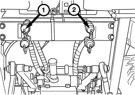
FIG. 126: The control lever (1) controls implement raising or lowering when the first set of remote couplers are used. The control lever (2) controls implement when second set of remote couplers are used (2-spool kit only).
Control lever(s) are spring-loaded to center neutral position, from normal raise or lower positions. Push the levers fully forward to hold in a detent providing a float position. Float position is used for loader and blade operations to allow the bucket or blade to float on top of the surface. The float position is also used in some implement applications.
FIG. 127: Remote couplers are located at the rear of the tractor. (Coupler(s): Consult with your dealer) The coupler set (1) is controlled by the inside control lever. The coupler set,(2) is controlled by the outside control lever. Implement hoses must be connected to each coupler set. When the specific control lever is pulled backward, the implement raises and, when pushed forward, the implement lowers. Male coupler tips (on implement hoses) must be compatible with tractor couplers, and must also be inserted fully and locked into tractor couplers to operate correctly.
CAUTION: Always lower implement to ground, shut off engine and relieve system pressure (by operating control levers with engine off) before connecting or disconnecting implement hoses.
CAUTION: Make sure all hydraulic hoses, couplers and cylinders are in good condition before use.
FIG. 128: Most implements require double-acting hydraulics. Each implement cylinder will have 2 hoses connected to it.
When single acting service is required (cylinder with only 1 hose), the upper coupler will be used. The selector function (1) must be turned to the left. The selector function is located at the right rear of the tractor on the back of the valve spools.
NOTE: For normal double-acting operation selector function must be turned to the right.
ROLL-OVER PROTECTIVE STRUCTURE (ROPS)
(Center type or Rear type)
FIG. 129: Tractor is equipped with a foldable roll-over protective structure (ROPS) (1) and seat belt.The seat belt should be worn at all times when being operated with the ROPS in the upright, locked position.
CAUTION: Do not weld, drill, bend or straighten damaged ROPS. Make sure all components are in correct working order in order to provide the intended protection.
Only original bolts and pins, or equivalent replacements, must be used and tightened to the correct torque value. Make sure the hinge joint is properly secured.
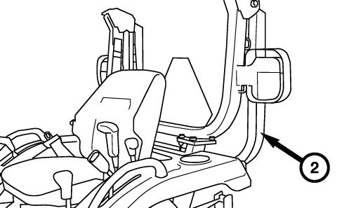
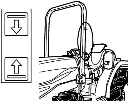
FIG. 130: (Rear type) When overhead clearance is restricted, the upper portion (2) of the ROPS may be folded down.
FIG. 131: To fold the upper portion of the ROPS, remove the locking pin (1) and lower the upper portion. The seat belt should not be worn when operating with the ROPS folded down.
CAUTION: Do not use the seat belt when the ROPS is folded down.Drive with extreme care. Tractor roll over may result in serious injury or death.
Adjust the rubber isolator, 3, on the upper-front of the lower U-frame to reduce vibration. Tighten the jam nut.
Center ROPS Type
Center ROPS type tractor is equipped with center mounted roll-over protective structure (Center ROPS). Seat belt must be worn when the ROPS is in the upright position.
The ROPS can be folded down only in the limited work such as going into and out from building, and work within orchard, hop or vineyard. After the work, return the ROPS to the upright position.
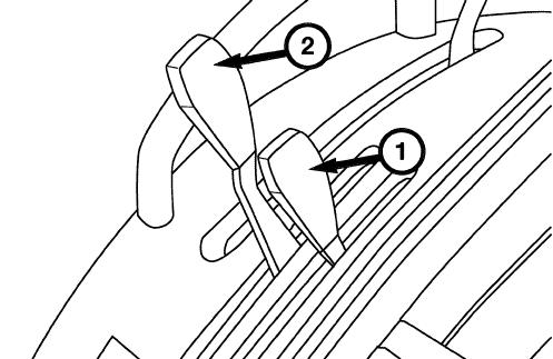
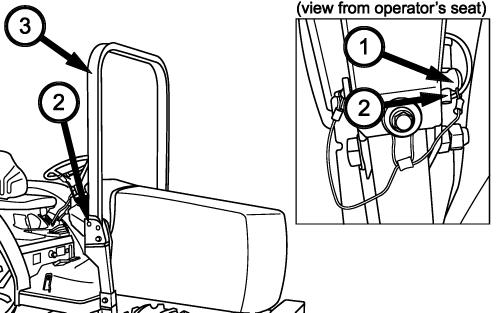
FIG. 132: After removing the lock pin (1) and the pin (2) the upper portion (3) of ROPS can be folded down to the front.
CAUTION: Do not use the seat belt when the ROPS is folded down.
FIG. 133: The upper portion (3) of ROPS can be fixed to folded position by installing the lock pin (1) and the pin(2).
WARNING: Except for the limited work such as going into and out from building, and work within orchard, hop or vineyard, do not operate the tractor with the ROPS folded down. Otherwise, this may result in serious injury when the tractor rolls over.
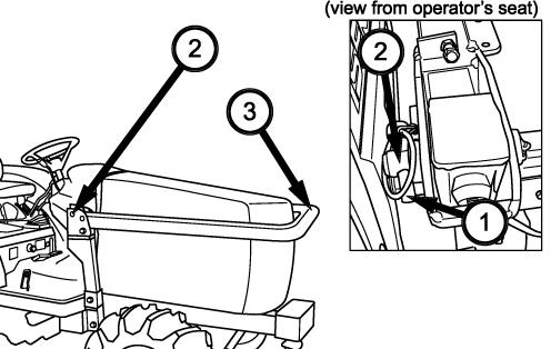
CAUTION: When folding down the ROPS, grab the limited area, between two labels (4) of the ROPS.
CAUTION: Do not use seatbelt when the ROPS is folded down.
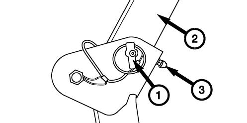
NOTE: Fig. 134 - To prevent PIN ASSY from being lost, bind the ring of wire by frame and rubber washer, and tighten up bolt (4).
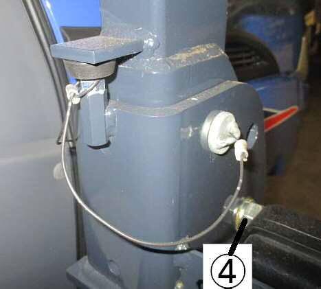
CAUTION: The purpose is fixing wire, tighten up the bolt so that the spring parts of it is crushed.
Front Hitch & Bumper Frame
FIG. 135: Front hitch (1) and bumper frame (2) are equipped on the tractor.
NOTE: Tractor should be balanced well with attaching the front weight to the front bumper when the heavy implement is attached to the rear side of the tractor. When attaching the front weights, consult your dealer.
Maximum number of the front weights are up to 6 weights.
Maximum Weight 90 kg (15 kg weight x 6 pieces)
Drawbar
FIG. 136: Drawbar (1) at rear of tractor allows pull type implements to be attached to tractor. Maximum vertical load on drawbar must not exceed 500 kg (1 102 lbs).
CAUTION: Pulling heavy loads will require extended braking distances. Reduce travel speed.
Make sure attachment is properly secured and safety chain is used.
NOTE: When using 3-point hitch, it may be necessary to remove drawbar by removing clips and pins (2) and sliding drawbar from bracket to improve operating clearance. This is particularly true with mounted implements using PTO drive.
Detaching Implements
CAUTION: Always use POSITION CONTROL to attach / detach implements to provide precise control of hitch.
Select a level area to detach and store the implement. Lower implement to ground by moving position control lever to DOWN. If necessary, adjust leveling crank on right lift link to level implement on ground.
Shut off engine, securely lock brakes and remove key from tractor.
Disconnect implement PTO drive shaft (as applicable). Detach top link from implement and place in storage position on tractor by engaging spring on top link in slot in rear center panel.
NOTE: Lengthening or shortening of top link may be required to permit disconnection from implement.
Rear Hitch
FIG. 137: Drawbar (1) at rear of tractor allows towed implements to be attached to tractor.
Tractor does not have any trailer braking system.
Follow strictly the instructions outlined in the operator’s manual of the mounted or trailed machinery or trailer, and not to operate the combination tractor – machine or tractor – trailer unless all instructions have been followed.
TABLE 9: Keep the maximum vertical load on the rear hitch, related to the rear tire size and type of hitch.
TABLE 9-2: Specification of rear hitch (TRH-1772A)
Type approval No.e13*2015/208*2016/1788NS*00055*00
Maximum horizontal load Not applicable
Towable mass3 500 kg
Maximum permissible vertical load on the coupling point500 kg
TABLE 10: Keep the permissible towable mass. When towing trailer, stay clear from the area between tractor and trailed vehicle.
TABLE 10: Permissible towable mass
TRH-1776A
Brake
Unbraked
Towable mass
R-and S Category vehicle
Total technically permissible towable mass (kg)
Total technically permissible masses of the tractor - trailer combination for each configuration of trailer braking (kg)
DrawbarRigid drawbarCentre-axleDrawbarRigid drawbarCentre-axle
Front Loader Fixation Point
Consult your dealer concerning the fixation points on tractor for the Front Loader.
Appropriate frames between the rear axle and the front frame might be necessary to obtain robust safety.
FALLING OBJECTS PROTECTIVE STRUCTURE (FOPS) & OPERATORS PROTECTION STRUCTURE (OPS) FIXATION POINT
Consult your dealer concerning the fixation points on tractor for the FOPS & OPS.
NOTE: FOPS and OPS are not standard equipment.
Towing
Consult your dealer for towing tractor as much as possible. If such cases as listed below happen call your ISEKI dealer as transmission might be broken.
• Although the engine runs, tractor cannot start to move.
• Unusual noise occurs.
FIG. 138: Hook up the rope to the front hitch (1). The distance between towing vehicle and tractor should be less than 5 m.
Move the range shift lever to the neutral position. Release the parking brake lock.
Jacking
When jacking tractor, place the tractor on level, hard ground which is sufficiently illuminated, otherwise unexpected accidents may occur. Follow the instructions listed below:
• Apply parking brakes.
• Disengage all PTO.
• Place all gear shift levers in neutral.
• Remove the starter key.
• Place the jack on level.
• Put tire chocks to the rear wheels when jacking up the front wheels.
• Put tire chocks to the front wheels when jacking up the rear wheels.
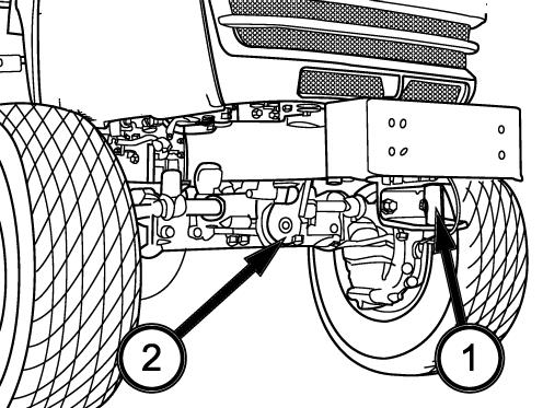
FIG. 139: When raising the rear axle, suitable shims, (1) should be wedged between the front axle and the front frame.
FIGS. 138 & 140: When raising the front axle, the jacking point is the front hitch (1) or the front pivot (2) For the rear axle, the jacking point is the rear hitch (3).