14 minute read
OPERATION


BREAK-IN PERIOD
Operation of tractor within the first 50 hours can be a major factor in determining the performance and life of the engine and tractor:
• The engine may be operated at full speed but excessive load should be avoided. If engine begins to “lug”, operate in a lower gear to maintain higher engine speed.
• Check coolant level and check engine, transmission and other oil levels frequently during break-in period. Watch for evidence of leakage of above fluids. Replenish levels as required and repair any leaks that may have formed.
• Tighten any nuts, bolts, or screws that may have loosened and tighten as necessary. This is especially true of wheel retaining bolts. All fasteners on this tractor are metric.
• Be observant of brake adjustment and readjust as required. Lining materials used on brake discs “bed in” in the first few hours of operation and may necessitate the need for early and frequent readjustment.
• Keep area around fuel tank filler clean and make sure diesel fuel is correct grade and free of contamination.
• Initial engine oil and oil filter change is after first 50 hours of operation. Subsequent change interval is every 200 hours for engine oil and every 200 hours fro engine oil filter.
CAUTION: Proper maintenance practices cannot be over-emphasized. They are required for safe operation. Consult ìLubrication and Maintenanceî section for full details.
Starting
Pre-Start Inspection
Prior to daily start-up of tractor, a few basic procedures should be followed to ensure tractor is in operating order to insure life and dependability:
• Make sure all safety shields are in place and secured properly.
• Make sure operator is instructed on correct and safe operation of tractor and related attachments or implements.
• Check coolant, engine oil and transmission oil levels and replenish as necessary.
• Check fan belt tension and adjust as required.
• Make sure radiator, air intake screens and radiator screen are clear of debris to provide maximum engine cooling.
• Check operation of clutch, brake and throttle controls. All controls must operate freely and be adjusted correctly.
• Conduct a general inspection of tires, tire pressure and wheel bolt torque. Observe for external signs of leakage and correct before operating tractor. Check steering for excessive looseness.
• Check for adequate fuel supply. It is recommended fuel tank be filled following each day’s use to reduce condensation and provide full tank for next use.
• Check operation of lights and warning flashers. If tractor is to be transported on public road, ensure slow-moving vehicle emblem is in place.
NOTE: Requirements may vary regarding use of warning flashers and slow-moving vehicle emblem depending on locality. Check local safety codes.
WARNING: Carefully read and understand the SAFETY section of this manual. Your life, and that of others, can be in danger during the starting of the tractor.
Always start and operate the engine in a well ventilated area.
If in an enclosed area, vent the exhaust to the outside.
DO NOT modify or tamper with the exhaust system.
Normal Starting
CAUTION: Do not attempt to start the tractor unless seated in the operatorís seat. Do not allow anyone on the tractor except for the operator.
FIGS. 82 & 83: To start the engine, proceed as follows:
1. Apply parking brake (1).
2. Place the gear shift lever and range gear shift lever (2) in the neutral position.
3. Make sure the rear PTO and mid PTO selector levers (3) are in the neutral position.
4. Fully depress the main clutch pedal (4) to disengage the clutch. (Mechanical / Synchro shuttle transmission)
5. Make sure the PTO switch (6) is in the OFF position. (“Independent PTO” type)
CAUTION: The operator being seated in the operatorís seat, the gearshift lever must be in neutral and the PTO levers must be in neutral to actuate safety switches and permit operation of the starter motor. (Hydrostatic transimission- be sure to keep HST pedal in neutral, except for Hydrostatic transmission - be sure to depress clutch pedal.)
6. Set the position control lever (5) and draft control lever (if equipped) in the down position.
7. Turn the main switch (7) to the “glow” position for 5-10 seconds.
8. Set the throttle lever (8) at half to the fully open position.
9. Turn the main switch (7) to the “on” position for 1-2 seconds, and then turn to the “start” position. Release the switch the moment engine starts.
10. Once the engine runs smoothly, set engine speed to approximately 1 500 min-1 to allow the engine and hydraulic system to warm up for several minutes. DO NOT LOAD A COLD ENGINE.
IMPORTANT: Do not crank engine for more than 10 seconds at a time. Allow starter to cool at least 20 seconds before repeating procedure. Never turn main switch to “start” with engine running. Severe damage will result.
FIG. 84: Battery charge indicator lamp and engine oil pressure lamp in indicator light strip should go out when the engine starts. If either light remains lit, STOP ENGINE IMMEDIATELY and investigate source of problem.
IMPORTANT: If engine will not start and run after several attempts, refer to “Maintenance” section in this manual and bleed any air that may be present in the fuel system.
Restarting Warm Engine
When restarting an engine that is still warm from previous use, the same procedure is used as with “Normal Starting” except step no. 6 may be omitted. Use of glow plugs is not necessary when starting a warm engine.
Cold Weather Starting
Procedure for starting an engine in colder ambient temperatures is identical to “Normal Starting” procedure except for the following:
• Longer use of glow plugs may be required. Instead of the normal 5-10 seconds, main switch may need to be selected to “glow” for 10-20 seconds to adequately warm engine combustion chambers.
• At temperatures below 4 °C (39 °F) use of No. 1 (No. 1-D) diesel fuel is recommended due to possible “fuel gelling” characteristics of No. 2 (No. 2-D) fuel at cold ambient temperature.
• Transmission oil will require additional warm-up time due to colder (thicker) oil. Refer to “Warm-Up Period” at right.
• Test all controls (steering, braking, etc.) prior to operating unit.
NOTE: Installation of accessory engine block heater is recommended in cold weather conditions. Consult your dealer.
IMPORTANT: Never use any kind of starting fluid to start engine equipped with glow plugs. Otherwise, such starting fluid will contact hot glow plug and it will result severe engine damage.
In any case that a booster battery is required to start engine, ensure a booster battery is connected in parallel with the original battery. When using a booster battery and booster cables, always connect the both positive (+) terminals first. Then install booster cable on the booster battery negative (-) terminal. And connect it to ground of the tractor or negative (-) terminal of the original battery. Finally make sure the booster cable ends are away from tractor body or other battery to prevent short circuit or any sparks.
Warm Up Period
After starting a cold engine, let engine idle at slow speed to make sure all engine components are lubricated.
In colder ambient temperatures, extended warm-up will be required to also warm hydraulic fluid and lubricate driveline components.
TABLE 1: Suggested warm-up period
32 & up0 & up5 to 10 min
32 to 240 to -1010 to 20 min
24 to -20-10 to -2020 to 30 min
-20 & less-20 & less30 or more
IMPORTANT: Improper warm-up can result in severe engine damage, hydraulic pump seizure, driveline bearing / gear damage and / or sluggish steering / braking
CAUTION: Make sure parking brake is securely applied and all controls are in neutral while warming unit. Do not leave unit unattended.
Operator Observations
Constant attention should be paid to the following points during operation:
• Engine oil pressure lamp will come on in case of low engine oil pressure. Stop engine immediately.
• Battery charge lamp will come on if battery is not being charged properly. Stop engine and investigate cause.
• Coolant temperature gauge needle will indicate H(hot) in case of overheated engine. Stop engine, allow to cool and investigate cause.
• Fuel gauge should not be allowed to (empty) as running out of fuel may result with need to bleed air from fuel system.
CAUTION: DO NOT attempt to service tractor with engine running or hot. Allow to cool.
NOTE: Refer to “Trouble-Shooting” when defect is indicated, to assist locating problem.
Starting Circuit Operation
Tractor is equipped with a starting system to protect the operator. To permit tractor to be started (start motor to operate), ALL the following is required:
Oparator seated on the seat.
Depress the clutch pedal(Mechanical and SynchroTransmission)
• Forward / Reverse Lever in Neutral(Synchro Transmisson)
Do not depress the HST pedal.(HST model)
Sub shift lever set to neutral position.(HST model and SynchroTransmission)
• Rear PTO Switch(Lever) in Off position
WARNING: Safety switch system is installed for your protection. DO NOT bypass or modify the safety start switch system. If the neutral start switch system does not operate properly as detailed above, contact your dealer immediately and have the system repaired.
Periodically check that the starting circuit is functioning correctly. The procedure for check is as follows:
1. Check that there are no bystanders around the tractor in order to avoid the inadvertently start.
2. Depress clutch and brake pedals. Attempt to start the tractor with the gear shift levers and PTO control switch OFF. The tractor should start.
3. Depress the clutch and brake pedals. Attempt to start the tractor with the gears engaged and the PTO switch ON. The tractor should NOT start.
4. Depress the clutch and brake pedals. Attempt to start the tractor with the gears in neutral and the PTO switch ON. The tractor should NOT start.
If starting system is not working correctly it must be repaired immediately by your dealer.
The starter will rotate when not sitting in the seat, but the engine will not start.
The engine will automatically stop about 3 seconds after the operator leaves the seat. Do not leave the seat while operating the tractor.
Ground Speed Selection
Mechanical / Synchro Shuttle Transmission
FIG. 85: Gear shift lever (1) provides 4 gear selections. These gear selections are compounded by range shift lever (2). The range shift lever provides 3 major changes in ground speed. Gear shift lever provides smaller ground speed changes.
Depress clutch pedal and position shift levers in desired positions. Depress brake pedals to release parking brake lock and then slowly release clutch pedal.
Should another transmission gear be desired:
• Range Shift - Depress the clutch pedal and shift gears after bringing the tractor to a complete stop.
• Gear shift - Depress clutch and brake pedals stopping the tractor. Select desired range lever position and continue with operation.
IMPORTANT: Depress clutch and stop tractor before shifting all shift levers.
TABLE 2: Speed chart (Mechanical transmission)
* Agri Tire (11.2-24) is only for tractor with center ROPS (A-type) and joystick (J-type).
FIG. 86: Forward or reverse travel is selected by the lever (1) on the steering column. (Synchro
(A) Forward
(B) Neutral
(C) Reverse
Moving the forward / reverse lever (1), forward will select forward travel. Moving the lever rearward will select reverse travel. Reverse travel speed is slightly slower than forward travel in the same gear speed selection. A new travel direction should be selected whenever the tractor is stopped.
CAUTION: Reduce engine speed before changing travel direction. Tractors with synchro shuttle require complete disengagement of main clutch (depressed clutch pedal) before moving forward / reverse lever.
Hydrostatic Transmission
FIGS. 87 & 88: The hydrostatic transmission provides infinite speed control in forward or reverse.
The range shift lever (1) provides major changes in ground speed. Tractors have snail, tortoise and hare speed selections.
Pedal (2) controls forward travel speed. As the pedal is progressively pushed down, a corresponding increase in ground speed will be noticed. When released, the pedal will return to neutral and the tractor stops traveling.
Reverse speed is obtained by pushing pedal (3) down. As the pedal is progressively pushed down, a corresponding increase in ground speed will be noticed. When released, the pedal will return to neutral and the tractor stops reversing.
WARNING: To avoid personal injury - Do not operate if tractor moves on level ground with foot off of HST control pedal. (Except while cruise control operation)
CAUTION: When the range shift lever is in Hare (H range), set engine speed between 1 200 min-1 and 1 500 min-1 by using hand throttle lever, depending on the attached implement.
TABLE 4: Arrangement of gears with appropriate ground speeds, in order from slow to fast, as shown in the chart below.
CAUTION: Before leaving the tractor unattended, make sure parking brakes are applied, rear mounted implement is lowered to the ground and the key is removed from the ignition switch.
Stopping Tractor
Mechanical / Synchro Shuttle Transmission
FIG. 89: Brake pedals (1) and (2) may be used independently to operate respective brake and assist turning at low speed operation. Unlatch brake pedals and use as required to assist turning.
When traveling on road or operating at high speed, brake pedals must be latched together with interlocking plate (3) so both brakes will apply at the same time.
CAUTION: Do not use individual wheel brakes, and latch brake pedals together using interlocking plate when traveling on roads or operating at high speed. Make sure brakes are adjusted evenly.
FIG. 90: To stop the tractor with regular gear transmission, move the throttle lever (4) forward, to reduce engine speed and slow travel. Depress the clutch pedal (5) and brake pedal (1) and (2) to stop. Position the range and gear shift lever (6), and forward / reverse lever (7) in neutral position.
Be sure to latch the brake pedals together, depress the brake pedals and pull parking brake lever (8) up firmly.
Allow engine speed to idle several minutes to allow even cooling. Then turn main switch to “off” shutting off engine. Lower 3-point hitch and remove key from ignition.
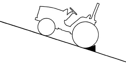
FIG. 91: Always park tractor on level area whenever possible. If hillside parking is necessary, securely block both rear wheels as shown.
NOTE: When stopping or parking tractor, be sure brakes are locked. With transmission of constant mesh design, tractor may have a tendency to creep (particularly with cold oil).
Hydrostatic Transmission
FIG. 92: To stop the tractor with a hydrostatic transmission, release the forward HST pedal (3).
This action will stop forward travel. Move the throttle lever (1) forward to reduce engine speed, depress the brake pedal (2) and set the parking brake lever (4). Move the range shift lever (5) to neutral position. Allow the engine to idle several minutes to allow even cooling, then turn the main switch to the “off” position, shutting off the engine.
Lower the 3-point hitch and remove the key from the main switch.
CAUTION: Make sure brakes are adjusted evenly.
CRUISE CONTROL (HYDROSTATIC TRANSMISSION)
Setting cruise control
FIGS. 93 & 94: Depress the forward HST pedal (3) and keep your intended speed, and shift the cruise control lever (6) to “ON” position.
CAUTION: Even though it is possible to engage cruise control when driving backward, do not use it at the time for safety reason.
Releasing cruise control
FIG. 93: Cruise control is released if the lever is returned to neutral position gradually or brake pedal (2) is depressed.
CAUTION: If cruise control is released by depressing brake pedal, it is dangerous because brake is engaged at the same time. Except for emergency case, release the cruise control by shifting cruise control lever to neutral position gradually.
WARNING: Cruise control should only be used in open spaces, without obstacles, with unobstructed view or traveling on road. You must also be thoroughly familiar with releasing cruise control.
CAUTION: When greasing, remove the cover (7) to complete the operation.
Differential Lock
• Mechanical / Synchro Shuttle Transmission
................................................Differential lock pedal
• Hydrostatic Transmission
.................................................Differential lock lever
FIGS. 96 & 97: When the differential lock (1) pedal or lever is lowered, both sides of the rear axle are locked together to ensure traction to both rear wheels. This is especially important when operating in loose soil or slippery conditions.
To engage the differential lock - Depress the clutch pedal and allow all rear wheel movement to stop. Depress the lock pedal or lever and slowly engage the clutch.
IMPORTANT: DO NOT engage with rear wheel(s) spinning as severe damage may result.
To disengage the differential lock - Depress the clutch pedal and release the differential lock pedal or lever. The lock pedal or lever should normally return to the “off” position.
NOTE: On occasion, differential lock pedal or lever may remain engaged due to torque difference exerted by rear wheels. In this case, tap brake pedals alternately while tractor is slowly in motion to release the pedal.
CAUTION: When differential lock is engaged, steering ability of tractor will be greatly reduced. Disengage before attempting a turn.
DO NOT use differential lock on hard surfaces or when transporting the tractor.
4-WHEEL DRIVE
FIG. 98: The 4-wheel drive shift lever (1) engages and disengages the drive for the front axle. With the lever down, the front axle (4WD) is engaged. With the lever up, the front axle is disengaged, and power is available to both front and rear axles.
NOTE: Illuminate the monitor lamp on the meter panel when 4WD control lever is pushed down.
IMPORTANT: Depress main clutch pedal and stop tractor before engaging or disengaging 4-wheel drive.
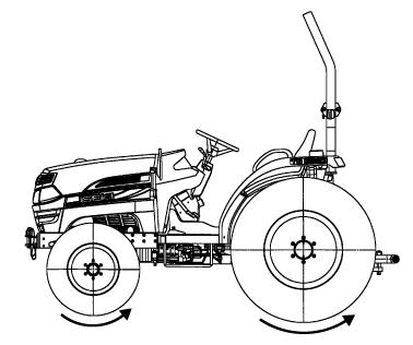
FIG. 99: When front axle is engaged, ground speed of front tires is slightly faster than the speed of the rear tires. This is to assist steering when 4-wheel drive is selected.
For this reason, the front axle must be disengaged when the tractor is transported or operated on a hard, dry surface. Failure to do so will result in rapid wear of front drive tires and possible driveline damage.
IMPORTANT: Always disengage front drive axle when operating in conditions with minimal wheel slippage (DRY OR HARD SURFACES).
If tire replacement is necessary, identical replacements must be installed to maintain correct front / rear axle ratio.
POWER TAKE-OFF (PTO)
WARNING: PTO shafts and PTO driven implements can be extremely dangerous. Observe the following important points:
DO NOT operate tractor without a PTO shield cover installed. The shield cover protects people from injury as well as the splines from damage.
Before attaching, adjusting or working on PTO driven implements, disengage the PTO, stop the engine and remove the key. DO NOT work under raised equipment.
Before engaging a PTO-driven implement, ALWAYS carefully raise and lower the implement using Position Control. Check clearances, PTO shaft sliding range and articulation.
Ensure that all PTO safety shields are in place at all times.
Ensure all PTO-driven implements are in good condition and conform to current standards.
When using a PTO-driven implement, make sure the universal joint does not interfere with PTO shield cover.
NEVER step across any driveline. DO NOT use the tractor drawbar or the implement drawbar as a step.
NEVER use the driveline as a step.
NEVER wear loose fitting clothes. Keep at least your height away from a rotating driveline.
Rear PTO Shaft
FIG. 100: PTO shaft (1) (6 splines, 35 mm) is provided at rear of the tractor to provide power to rear-mounted PTO driven implement.
Protective cover shall be installed, when it is not in use.
Normal rear PTO shaft operating speed:
540 PTO min-1 @ 2 484 min-1
1 000 PTO min-1 @ 2 290 min-1
IMPORTANT: When rear PTO is used with 3-point mounted equipment, it may be necessary to remove drawbar (2) at rear of tractor. Some types of mounted equipment, when lowered, may allow PTO shaft to contact drawbar.
FIG. 101: Implement drive shaft shown connected to tractor rear PTO shaft.
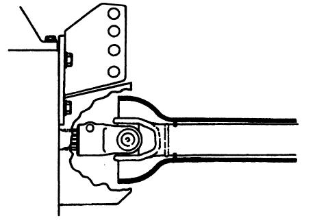
CAUTION: Make sure all PTO shields are installed on tractor and equipment. Before cleaning or adjusting tractor or PTO driven machine, SHUT OFF ENGINE AND DISENGAGE PTO.
Mid PTO Shaft (Rear ROPS Type)
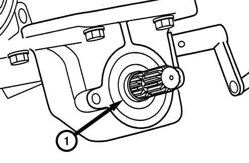
FIG. 102: Mid PTO (1) (15 splines, 25 mm) is located at the bottom of the transmission and it is facing forward. The mid PTO provides power to mid-mounted or front-mounted PTO driven implement.
Mid PTO shaft operating speed:
(TH4295)
2 000 min-1 @ 2 500 min-1
(TH4335 / TH4365)
2 080 min-1 @ 2 600 min-1
Protective cover must be installed when Mid PTO is not in use.
CAUTION: Make sure all PTO shields are installed on tractor and equipment. Before cleaning or adjusting tractor or any PTO driven machine, SHUT OFF ENGINE AND DISENGAGE PTO.