14 minute read
MAJOR COMPONENTS


FIG.
Identification and terminology of major components, as given in this operator’s manual, are as follows: terminology of major components, as given in this operator’s manual, are as follows:
16. Front Hitch
17.
19. Transmission
20.
22.
27.
28.
29.
30.
INSTRUMENTS & CONTROLS
General layout and location of controls within operator’s area on tractor. Specific use of these controls is given later in this section and also in “Operation” section of this operator’s manual:
1. Steering Wheel
2.
3.
10.
11.
12.
13. Gear Shift Lever
14. 3-Point Hitch Draft Control Lever (accessory)
15. 3-Point Hitch Position Control Lever
16. Joystick Control Lever(accessory)
17. Operator’s Seat
18. External Auxiliary Hydraulics Lever (accessory)
19. External Auxiliary Hydraulics Lever (accessory)
20. Mid Power Take-OFF (PTO) Selector Lever (M-type)
21. 4-Wheel Drive (4WD) Shift lever
22. Combination Switch
23. Hazard Signal Switch
CAUTION: Become familiar with all operating controls prior to operating tractor. Read this manual in its entirety before starting.
13.
16.
17.
Instrument Panel
FIG. 37: Arrangement of gauges. Control switches and indicators located in instrument panel. Items are detailed in the descriptions that follow:
Main Switch
FIG. 38: Main switch (1) has the 4 following positions:
• OFF - Tractor engine and all electrical circuits off.(except for head light, turn / hazard position light, tail light, working lamp) Key can be removed.
• ON - Power supplied to all circuits. Normal operating position. Linkage on fuel injection pump moves (electrically) to the run position.
• GLOW - Energizes glow plugs to pre-heat combustion chambers and assist starting.
• START - Starter activated. This position spring loaded to “ON”.
Electric Fuel Shut-Off
Turning main switch to off position will stop engine.
NOTE: Main switch must be turned to “ON” before any circuits will operate. Clutch pedal must be depressed(Except for hydrostatic transmission)PTO switch must be off and gear shift lever and HST pedal (hydrostatic transmission only )in neutral before engine can be started.
This tractor is equipped with an electric fuel shut off. When main switch (1) is turned to “start”, “on”, or “glow” position and gear shift lever is placed in neutral, a solenoid moves the fuel linkage on injection pump to run position to start engine. When main switch is turned to “off”, solenoid moves fuel linkage to off position to stop engine.
Indicator Light Strip
FIG. 39: Indicator light strip (2) contains several warning lights to monitor certain functions. Currently used positions (from right to left) are:
• Main (High) Beam - Illuminates when headlamps in front grille are selected to high beam position by light switch.
• Power Take-Off (PTO) - Illuminates when PTO control switch is moved to engage PTO clutch pack (PTO operating). Light will go out when PTO switch is moved to off.
• Engine Oil Pressure - Illuminates if engine oil pressure is low. If light comes on while engine is running, shut off engine immediately and investigate cause.
• Battery Charge - Illuminates when main switch is turned “ON” and will go out after engine starts, to indicate battery is being charged.
• Trailer Monitor - Blink when warning lamp switch is turned on.
• Parking Brake - Illuminates when the parking brake lever is pulled to upward to indicate engaged parking brake.
• 4WD Monitor - Illuminated when the 4-wheel drive lever is pushed downward, to indicate the front axle (4WD) is engaged.
Coolant Temperature Gauge
FIG. 40: Gauge (3) indicates engine coolant temperature when main switch is selected to ON
• - Shows too cool temperature for severe work. Allow to warm (needle in mid position) before applying heavy load.
• - Indicates overheating (red area on gauge). Reduce engine speed to idle, allow to run at no load several minutes and investigate cause (refer to “Troubleshooting”).
CAUTION: Do not service hot engine. Allow to completely cool before servicing or removing radiator cap.
Tachometer
FIG. 41: Gauge (4) indicates engine speed in crank shaft revolutions per minute (min-1). Index is also provided to show rear PTO speed of 540 at approximately 2 484 min-1.
Normally, the PTO speed should be between 540 and 600. Operating the PTO at a speed above 600 is too fast, and may result in a breakdown of the tractor or implement.
Hourmeter in center of gauge indicates engine and tractor use to assist in maintenance intervals. The extreme right digit indicates 1 / 10 hour increments.
Fuel Gauge
FIG. 42: Gauge (5) indicates level of diesel fuel in fuel tank when main switch is “ON”
NOTE: Use only clean diesel fuel and clean area to prevent dirt / water entry into fuel tank when refilling. DO NOT run out of fuel as bleeding air from the system will be required. Keep fuel tank full to minimize condensation.
CAUTION: DO NOT refill fuel tank with engine running or hot. Allow cooling period. DO NOT smoke near fuel tank. Clean up any spilled fuel.
Horn / Light Turn Switch
FIGS. 43 & 44: Horn / Light Turn Switch.
Horn Switch (6) - Horn will sound when center switch button is depressed.
Light Switch (7) - Is a rotary switch with 3 operating positions:
• OFF - Fully counterclockwise. All lights off.
• 1st - Front clearance lamps, rear tail lights, license plate light and instrument panel illumination.
• 2nd - Main beam headlamps in addition to lamps lighted at 1st position.
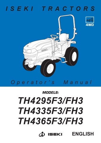
NOTE: High beam / Low beam selection
High beam and low beam are selected by the position of switch knob.
Middle position: low beam
Down position: high beam
NOTE: Passing switch
Passing switch is turned on when switch knob is pulled to upward.
NOTE: When high beam is selected (2nd position), light in indicator light will come on.
Turn Switch (8) - Operate switch handle in direction tractor is being turned. The appropriate flashing amber warning light (ROPS-mounted) will operate as turn signal. Return switch to center position to cancel.
NOTE: Turn lights will not self-cancel. Select turn / hazard light switch to center position after completing turn.
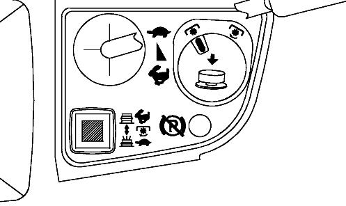
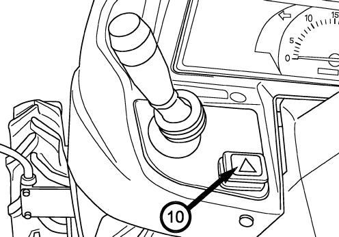
FIG. 45: Hazard Light Switch, - Press switch (10) to turn on hazard lights. Both flashing amber warning lights will operate at the same time.
CAUTION: Hazard lights must be used any time tractor is driven on public roadway. Consult local agencies for other marking requirements.
FIG. 46: Turn / hazard indicator lights (11) and (12) will operate with ROPS-mounted warning lights. This provides operator with easy indication of warning light selection.
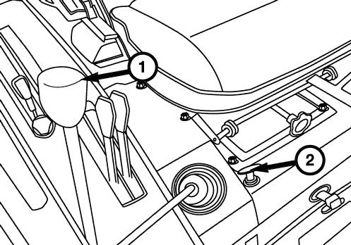
Power Take-Off (PTO) Switch (Hydrostatic Transmission )
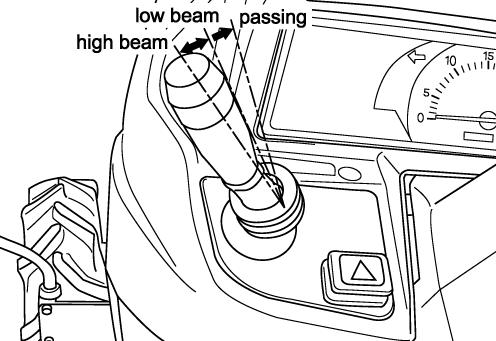
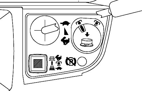
FIGS. 47 & 48: A dial-type safety switch (1) is used to engage and disengage the PTO drive system. The switch must first be turned to right and then pulled up to engage PTO. When engaged, the PTO indicator light in the indicator light strip will illuminate.
A PTO selectable switch (2) is used to adjust PTO clutch modulation.
Push on: soft start (button depressed illuminated) - for high inertia loads
Push off: standard start (button out and not illuminated)
IMPORTANT: PTO switch is equipped with a lockout to prevent accidental engagement of PTO system. To engage PTO, first turn switch clockwise and then pull up it. DO NOT FORCE SWITCH.
NOTE: PTO switch (1) must be used in conjunction with rear PTO selector lever, to left of operator’s seat, when rear PTO is used. Refer to “Operation” section for complete details.
When PTO control switch is “ON” the engine cannot be started. Always switch off PTO and depress main clutch pedal to start engine.
This switch is equipped with only “Independent PTO” specification model (Hydrostatic transmission type ).
WARNING: Always shut off PTO and shut off tractor engine before servicing PTO driven implement. Allow all movement and motion to stop before leaving operator’s seat.
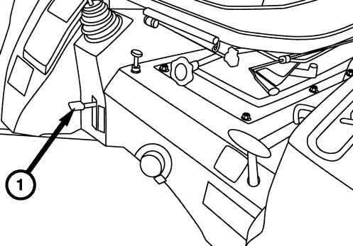
CLUTCH PEDAL (MECHANICAL / SYNCHRO SHUTTLE TRANSMISSION)
FIG. 49: The foot pedal (1) disengages the engine from the transmission when fully depressed, to permit engine starting, selecting or changing gears and stopping tractor movement. 4-wheel drive selection also requires clutch disengagement. Slowly raising the pedal will engage the clutch and start the tractor moving in the selected gear.
NOTE: Depress clutch pedal quickly to prevent abnormal wear. Raise clutch pedal smoothly to prevent sudden movement. DO NOT “ride” clutch pedal with your foot.
IMPORTANT: Clutch pedal free-play must be adjusted correctly. See Clutch Free-Play Adjustment for instructions.
Brakes
CAUTION: For towing safety, the towed equipment, when fully loaded, should not exceed 1.5 times weight of towing unit.
Brake Pedals
FIG. 50: The inner brake pedal (1) and outer brake pedal (2) independently control the respective left and right wheel brakes to assist in turning.
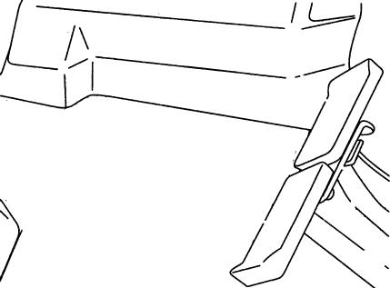
During traveling on road or operating at high speed, the brake pedals should be latched together using the interlocking plate (3).
CAUTION: Do not use individual wheel brakes and latch brake pedals together using interlocking plate when traveling on roads or operating at high speed. Make sure brakes are adjusted evenly.
FIG. 51: Tractor with hydrostatic transmission do not have individual wheel brakes but single brake pedal (4).
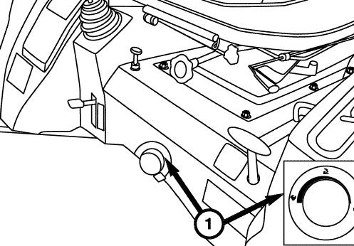
Parking Brake lever
WARNING: ALWAYS apply the parking brake before dismounting from the tractor.
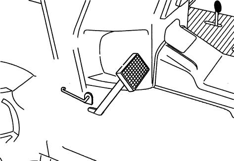
FIG. 52: The parking brake acts on the tractor rear wheels. To engage the brake, pull upward the parking brake lever (5), to lock brakes in applied position. To release the parking brake, press the button on the end of the lever and push the lever down.
Ensure the parking brake is fully released before driving off.
NOTE: When the parking brake is not applied and engine is turned off, warning alarm and parking brake warning lamp (6) (at the right hand side of mater panel)will let you know to apply the parking brake.
Engine Speed Controls
CAUTION: Always select engine speed to ensure safe operation. Reduce speed prior to turning or reversing tractor.
IMPORTANT: DO NOT “race” or excessively load cold engine.
FIGS. 54 & 55: Throttle lever (1) - Controls engine speed and will remain in position selected by the operator. With hand lever forward ( ), engine will idle. Engine speed increases as lever is pulled progressively rearward ( ).
Accelerator pedal (2) - Will override setting of the throttle lever for increased engine speed. When the pedal is released, engine speed returns to the throttle lever setting.
CAUTION: When using foot throttle pedal, the hand throttle lever must be in the low idle speed position. This ensures maximum “engine braking” when pedal is released.
NOTE: Accelerator pedal (2), is not equipped with Hydrostatic transmission type.
Transmission Shift Levers
(Mechanical transmission) .........................F9, R3 type
• Forward 9 gear speed
• Reverse 3 gear speed (Synchro shuttle transmission) ..................F8, R8 type
• Forward 8 gear speed
• Reverse 8 gear speed (Hydrostatic transmission) .........................F3, R3 type
• Forward 3 gear speed
• Reverse 3 gear speed
NOTE: F12, R12 (with creep speed) is available as option for synchro shuttle transmission.
(Mechanical Transmission)
2 shift levers are used to select ground travel speed through different gear reductions within the drive train.
IMPORTANT: All range and gear change selections require complete disengagement of main clutch (depressing pedal).
Range and Gear Shift Levers
FIG. 56: The range shift lever (1) and gear shift lever (2) are located to the left of the operator’s seat. The range shift lever(1) provides 3 major speed changes.
FIG. 57: The gear shift lever (2) provides 3 forward and 1 reverse gear selection. These gear selections provide a small change in ground speeds and / or direction.
In total, 9 forward and 3 reverse gear speeds are possible.
NOTE: Range shift lever must be in neutral position before the tractor can be started.
(Synchro Shuttle Transmission)
3 shift levers are used to select ground travel speed and direction through different gear reductions within the drive train. Forward and reverse travel directions are also possible in all gear selections.
IMPORTANT: All range and gear change selections require complete disengagement of main clutch (depressing pedal).
Forward / Reverse Lever
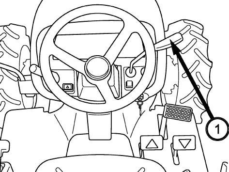
FIG. 58: Forward or reverse travel is selected by the lever, 1, on the steering column.
(A) Forward
(B) Neutral
(C) Reverse
Moving the forward / reverse lever (1) forward will select forward travel. Moving the lever rearward will select reverse travel. Reverse travel speed is slightly slower than forward travel in the same gear speed selection. A new travel direction should be selected whenever the tractor is stopped.
CAUTION: Reduce engine speed before changing travel direction. Tractors with synchro shuttle require complete disengagement of main clutch (depressed clutch pedal) before moving forward / reverse lever.
Range and Gear Shift Levers
FIG. 59: The range shift lever and gear shift lever are located to the left of the operator’s seat. The gear shift lever provides 4 smaller gear speed changes within each range, from first through 4th gear positions.
The range shift lever (2) provides 2 speed ranges, high and low.
FIG. 60: In total 8 forward and 8 reverse gear speeds are possible. The constant-mesh gears allow the gear shift lever (3) and range shift lever to be changed with the tractor completely stopped (with main clutch pedal and brake pedal depressed).
When you select the creeper speed type transmission, it is possible to select forward, 12, reverse, 12, speed. Creep speed will be position on the center of range speed selection lever (2).
(Hydrostatic Transmission)
FIG. 61: 1 shift lever is used to select a range of ground travel speed through different gear reductions within the drive train.
A hydrostatic control unit allows infinitely variable speeds, from zero to top speed, in each range.
WARNING: To avoid personal injury
- Do not operate if tractor moves on level ground with foot off of HST control pedal. (Except while cruise control operation)
- Contact your local ISEKI dealer.
Range and Cruise Control Lever
FIGS. 62 & 63: The range shift lever provides 3 major speed changes (1).
The hydrostatic cruise control lever (2) actuates the hydrostatic control unit for forward travel only. This lever allows the operator to set a constant speed for operating in large areas, road travel, etc.
Differential Lock
FIGS. 64 & 65: When the differential lock (1) pedal or lever is lowered, both sides of the rear axle are locked together to ensure traction to both rear wheels. This is especially important when operating in loose soil or slippery conditions.
To engage the differential lock - Depress the clutch pedal or lever and allow all rear wheel movement to stop. Depress the lock pedal or lever and slowly engage the clutch.
IMPORTANT: DO NOT engage with rear wheel (s) spinning as severe damage may result.
To disengage the differential lock - Depress the clutch pedal and release the differential lock pedal or lever. The lock pedal or lever should normally return to the “off” position.
NOTE: On occasion, differential lock pedal or lever may remain engaged due to torque difference exerted by rear wheels. In this case, tap brake pedals alternately while tractor is slowly in motion to release the pedal.
CAUTION: When differential lock is engaged, steering ability of tractor will be greatly reduced. Disengage before attempting a turn.
CAUTION: DO NOT use differential lock on hard surfaces or when transporting the tractor.
4-WHEEL DRIVE
FIG. 66: The 4-wheel drive shift lever (1) engages and disengages the drive for the front axle. With the lever down, the front axle (4WD) is engaged. With the lever up, the front axle is disengaged, and power is available to both front and rear axles.
NOTE: 4WD indicator lamp will be illuminated when you push down the 4WD control lever.
IMPORTANT: Depress main clutch pedal and stop tractor before engaging or disengaging 4-wheel drive.
When front axle is engaged, ground speed of front tires is slightly faster than the speed of the rear tires. This is to assist steering when 4-wheel drive is selected.
For this reason, the front axle must be disengaged when the tractor is transported or operated on a hard, dry surface. Failure to do so will result in rapid wear of front drive tires and possible driveline damage.
IMPORTANT: Always disengage front drive axle when operating in conditions with minimal wheel slippage (DRY OR HARD SURFACES).
IMPORTANT: If tire replacement is necessary, identical replacements must be installed to maintain correct front / rear axle ratio.
REAR PTO SELECTOR LEVER
FIG. 67: Rear PTO (power takeoff) selector lever (1) controls rear PTO on tractor.
When lever is backward, 540 min-1 rear PTO is selected.
When lever is forward 1 000 min-1 rear PTO is selected.
When returned to rear neutral (N) position, the gear lever is disengaged. (In case of independent clutch model)
Rear PTO selector lever is operated with PTO control switch on instrument panel. Refer to “Operation” selection for complete details.
IMPORTANT: Before moving rear PTO selector lever, PTO control switch on steering column must be off.
CAUTION: Always shut off PTO and shut off tractor engine before servicing PTO driven implement. Allow all movement and motion to stop before leaving operator’s seat.
Mid Pto Selector Lever
FIG. 71: The mid PTO selector lever (1) controls the mid PTO on the tractor.
When the lever is shifted Forward, the mid PTO operates at 2 080 min-1 (when engine speed is 2 600 min-1). When lever is returned, neutral is selected, and the mid PTO will stop rotating.
The mid PTO selector lever should be used with the PTO control switch on the instrument panel. Refer to the “Operation” section for complete details.
IMPORTANT: The PTO control switch must be set to Off when the mid PTO selector lever is operated.
Position Control
Position control is used when attaching or detaching implements and other operations requiring the implement to be kept at a constant height above the ground. It is also used with tool bars having flexible row units and implements equipped with gauge (support) wheels.
FIG. 74: The position control lever maintains hitch position at a constant height in relation to the tractor. As the position control lever (1) is moved backward, hitch and implement are raised. Moving the lever forward will lower hitch to selected position. Each lever setting provides a specific hitch and implement position.
The front lever stopper (2) can be set to contact the position control lever in the implement work position. This enables the implement to be returned to the identical position after the hitch has been raised for turning, transporting, etc.
The rear lever stopper (3) can be set to limit raising height, if required.
NOTE: When starting engine, ensure implement is lowered to the ground and lever is fully forward. This reduces load on starter due to hitch trying to raise when engine is cranked.
To begin work, align the tractor and implement in the field and move the position control lever (1) forward (toward DOWN). Adjust implement height using the position control lever and set the adjustable stoppers(2) and (3) as desired.
When turning, move position control lever backward (toward UP) to raise the implement and permit completion of turn. Return the implement to the work position by selecting the position control lever to the previous position against the stoppers. To finish work and transport, pull position control lever rearward fully to UP position.
Draft control (Center ROPS Type)
FIG. 75: Draft control lever (1) adjusts height of 3-point hitch according to the “draft” or pull of groundengaging implements. This provides consistent load on tractor and provides weight transfer to tractor rear wheels to reduce wheel slippage. Lever stoppers (2) and (3) can be adjusted within slot to limit implement raising / lowering.
CAUTION: Use position control lever (1) when attaching or detaching implements.
NOTE: When starting engine, ensure implement is lowered to the ground and both levers are fully forward. This reduces load on starter due to hitch trying to raise when engine is cranked.
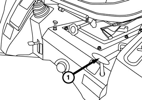
Lowering Rate Control Knob
FIG. 76: The lowering rate knob (1) adjusts the rate of drop of the 3-point hitch and implement. Turn knob clockwise to slow drop rate (increase lowering time), counterclockwise to increase drop rate (decrease lowering time). Turning the knob fully clockwise will lock the implement (or hitch) in raised position for transport.
CAUTION: When working on or around mounted implements, always lower to ground prior to work. If implement must be raised, always block implement and lower links securely.
Joystick
Control Lever (J-TYPE)
FIG. 77: The joystick control lever (1) can be used to determine the front loader boom position and bucket position. The lever is located to the front on the right side of the seat.
NOTE: Other type than J-type can equip joystick as option.
FIG. 78: The Raise, Lower, Free Flow operations for the boom, and Roll Back, Dump, Fast Dump operations for the bucket can be controlled with the joystick control lever. The raise and lower operations for the boom, and roll back and dump operations for the bucket automatically return to neutral when the lever is released.
A detent device retains the joystick in the boom float position.
WARNING: Do not operate the joystick except when seated in the tractor. The front loader may operate unexpectedly, causing personal injury.
NOTE: When the joystick is operated on a tractor without a front loader, the relief valve may be operated, causing the 3-point link to stop operating.