21 minute read
LUBRICATION & PERIODIC MAINTENANCE


SPECIFICATIONS & CAPACITIES
Use oil of the quality recommended by ISEKI. API Service “CC”.
(Narrow type front axle)
NOTE: Change intervals stated above are for normal usage. Due to adverse operating conditions that may be experienced (extremely dusty or muddy), change intervals may need to be more frequent.
LUBRICATION / FILL POINTS
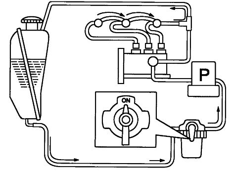
FIG. 141: General layout of lubrication, fill and drain locations on tractor:
TABLE 11: Type of lubrication (Mechanical / Synchro shuttle transmission)
Ref.Description:Type:
1CrankcaseEngine Oil
2Engine RadiatorCoolant
3 Radiator Overflow Reservoir Coolant
4Fuel TankDiesel Fuel
5Rear HousingHydraulic Oil
64WD AxleHydraulic Oil
7Axle Pivots (4WD)Grease
8Tie Rod EndsGrease
9Clutch PedalGrease
10Brake PivotsGrease
11Draft LinkageGrease
12 Sub Change Linkage nipple Grease
TABLE 12: Type of lubrication (Hydrostatic transmission)
Ref.Description:Type:
1CrankcaseEngine Oil
2Engine RadiatorCoolant
3 Radiator Overflow Reservoir Coolant
4Fuel TankDiesel Fuel
5Rear HousingHydraulic Oil
64WD AxleHydraulic Oil
7Axle Pivots (4WD)Grease
8Tie Rod EndsGrease
9HST PedalGrease
10Brake PivotsGrease
11Cruise control PivotGrease
12 Sub Change Linkage nipple Grease
: Inspect, replenish or adjust
: Replace
: Clean or wash
: Replacement or servicing at authorized service facility recommended. TABLE 13: Maintenance table
Opening / Closing Hood
FIG. 142: Release the lock of the hood by using tool (1) attached to the key. Pull upward the hood and lock it by retaining stay in the hood.
Close in reverse order, engine hood will be necessary to push downward on locks and then turn 1 / 4 counterclockwise to secure.
FIG. 143: When top the front grille (2) is pulled up, the lock can be disengage. Disconnect the headlamp wiring couplers and lift front grille upward to disengage the lower hooks and remove it from the tractor. When reinstalling front grille, place the grille on the lower hook and push on the top.
Removing / Reinstalling Side Cover
FIG. 144: When top of the side cover (3) is pulled out the lock can be disengaged.
The cover can be removed by slipping the side cover off of the 2 hinges on the bottom.
When reinstalling the side cover, place the cover on the hinges at the bottom, and push on the top.
The side cover (left) can be removed with the same procedure.
The muffler is adjacent to the left side cover. Make sure to allow it to cool before removing.
Lubrication Details
Grease Fittings
Lubricate all grease fittings every 50 hours of operation. Clean grease gun and fittings before and after greasing to prevent contamination from dirt.
NOTE: When operating in muddy or extremely wet conditions, daily lubrication of fittings is recommended.
Engine Oil & Filter
Engine oil and filter should be changed after first 50 hours of operation and then engine oil replace every 200 hours and engine oil filter replace every 200 hours thereafter.
FIG. 145: To Check Engine Oil Level - Park tractor on level ground. Make sure to allow the engine to cool sufficiently before checking the engine. Pull out dipstick (1) and check that oil level is between upper limit, F, and lower limit, L, on dipstick. Wipe off dipstick, momentarily reinstall in engine and check oil level again.
Add oil through filler opening (2) as required.
NOTE: Add oil slowly to assist in venting air from crankcase.
FIG. 146: To Change Engine Oil - Operate tractor until oil is adequately warmed. Remove drain plug(s) (3) from engine and allow all oil to drain.
Reinstall drain plug(s) and fill engine crankcase to upper limit on dipstick.
FIG. 147: To Replace Engine Oil Filter - Remove element (4) from engine and discard. Make sure original filter gasket has been removed.
Lubricate new gasket on replacement element with clean engine oil. Screw on new element until gasket contacts adapter and then tighten element 1 / 2 turn more.
Clean spilled oil and refill crankcase. Start engine, check for leaks and replenish oil level as required.
IMPORTANT: Engine warranty is valid only when original engine maker manufacturer's oil filter is used.
Transmission Oil & Filters
Transmission oil lubricates transmission, center housing, and rear axles and also serves as hydraulic fluid. Transmission oil and filter should be changed after first 50 hours of operation and then every 200 hours thereafter.
FIG. 148: To Check Transmission Oil Level - Park tractor on level ground, and remove the dipstick (1). Oil level should be indicated between the upper limit A and the end of dipstick B.
Oil level is replenished, as necessary, by removing filler plug (2) and adding oil through filler opening.
NOTE: Adding oil to transmission will also maintain correct oil level in center housing and rear axles.
IMPORTANT: Completely lower 3-point hitch prior to draining transmission oil.
Transmission Oil Filter
(Mechanical Transmission)
FIG. 150: To Replace Transmission Oil Filter – Drain transmission oil, and unscrew transmission filter (1) from adaptor. Use filter wrench.
Clean adapter and lubricate seat on new filter. Install until filter gasket contacts adapter and tighten additional 2 / 3 turn, by hand. Do not use filter wrench to tighten. Make sure that oil filter cartridge includes magnetic cartridge (2).
(Hydrostatic Transmission)
FIG. 151: To Replace Transmission Oil Filter (Sub) –Always replace the transmission oil filter while oil is removed. Carefully unscrew the oil filter (1) from its transmission. Use filter wrench.
Clean the filter adapter and lubricate the O-ring on the replacement filter adapter with clean transmission oil. Install the new filter until O-ring contacts the transmission and tighten additional 2 / 3 turn by hand. Do not use a filter wrench to install the filter. Replace the cartridge after the first 50 hours, and then every 200 hours.
FIG. 152: To clean Transmission Oil Filter (Suction)Clean the transmission oil filter while oil is removed. Loosen bolt (3) and draw out filter (1). When assembling, apply grease on O-ring (2) so as not to damage.
Front Axle Oil
Front drive axle has a common oil level for front differential housing and each wheel reduction unit. Oil level should be checked every 200 hours of tractor operation. The oil should be changed every 600 hours of operation (indicated on Hourmeter).
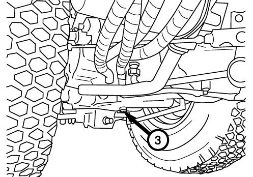
FIG. 153: To Check Oil Level -Park tractor on level ground and then remove oil level plug (1). Oil should be level with or slightly below level plug opening. Remove fill plug (2) and add oil until oil is expressed from level plug opening. Replace level plug and fill plug.
To Change Oil -Remove drain plugs (3) from both wheel reduction units. When all oil has drained, replace drain plugs and fill housing to level plug opening. Replace level plug and fill plug.
Checking / Replenishing Coolant
FIG. 154: The radiator is provided with a reserve tank (1) to maintain the coolant in the radiator at the proper level. Check the level in this reserve tank during the daily inspection.
Open the hood, and confirm that the coolant in the reserve tank is between FULL and LOW.
If the coolant level is low, add coolant to the reserve tank up the FULL level.
FIG. 155: When the coolant level is below the LOW level, remove the radiator cap (2) after allowing the engine to cool sufficiently, and confirm that there is an adequate amount of coolant in the radiator.
CAUTION: Do not open the radiator cap except when checking or replacing the coolant. Make sure to allow the engine to cool sufficiently before opening the cap. If the cap is opened while the engine is hot, coolant may be discharged, resulting in a burn or other injury.
IMPORTANT: Do not fill the reserve tank higher than the FULL level. This will prevent the radiator from functioning optimally, and may result in leakage of coolant.
Flushing Radiator / Replacing Coolant
FIG. 156: Open the drain cock (3) at the right side of the engine to drain coolant. Open the radiator cap (2) at the same time to help allow the coolant to drain. Remove the reserve tank (1) to drain coolant from it.
Thoroughly flush out the inside of the radiator with tap water.
Close the drain cock (3) and pour coolant into the reserve tank up to the FULL level to fill the radiator.
FIG. 157: Securely close the radiator cap (2) and reserve tank cap, and start the engine, allowing it to run for about 5 minutes in the mid speed range (Approx. 1 500 min-1). Then stop the engine.
When the engine cools, the coolant in the reserve tank will be sucked into the radiator. Add coolant to the reserve tank up to the FULL level.
Use of Anti-Freeze
Freezing of the coolant may result in damage to the engine. Mix in anti-freeze (Long Life Coolant) when the outside temperature will drop below 0 °C (32 °F) during the winter.
The mixture ratio of anti-freeze differs depending upon the anti-freeze manufacturer and temperature. Follow the instruction for the anti-freeze.
Cleaning of Radiator
WARNING: Make sure to stop the engine when cleaning the radiator. Placing your hands in this area while the engine is operating may result in serious injury.
FIG. 158: Cleaning Insect Net (1)
When the tractor is operated in fields or at night, the insect net may become clogged with grass, straw, insects and other matter.
Open the hood, pull out the insect net and clean it.
Cleaning Radiator Core (2)
Wash away any dirt or other foreign matter in between the fins with tap water.
IMPORTANT: When the radiator becomes clogged, it will overheat, resulting in increased oil consumption. Be careful not to apply high pressure water directly to the radiator as this may result in deformation of the fins. Do not directly spray water on the electrical wiring or electrical parts around the engine.
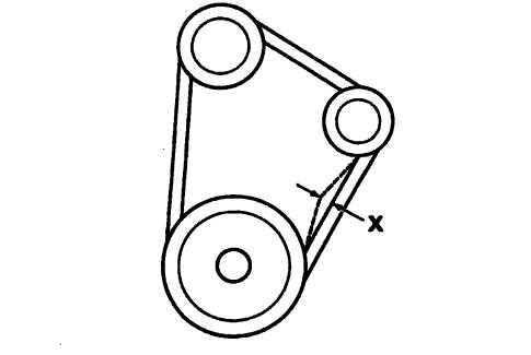
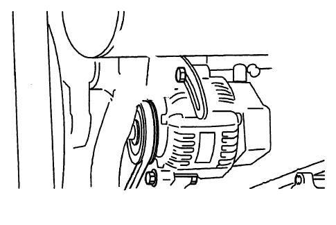
FIG. 159: Correct fan belt tension helps to insure adequate coolant flow through cylinder block and radiator. Belt is correctly tensioned when belt deflection is approximately 14 mm when thumb pressure (10 kgf) is exerted at center of belt span.
CAUTION: Due to muffler position, allow it to cool before checking or adjusting fan belt tension.
FIG. 160: To adjust belt tension, loosen alternator pivot bolt (1) and tensioning bracket bolt (2). Pull outward on top of alternator to correctly tension belt and tighten bolt (2) first and then tighten pivot bolt (1).
IMPORTANT: Do not pry against alternator housing or pulley. Carefully pry against alternator mounting flange to prevent damage.
Cleaning Air Cleaner / Evacuator Valve
FIG. 161: Open the hood, and remove the left side cover and front grill.
Press the evacuator valve (2) to discharge any dirt inside.
If there is moisture, wipe the inside of the air cleaner (1) with a rag.
FIG. 162: Cleaning / Replacing Air Cleaner Filter Element
Remove the clip (3) and take the filter element (4) out of the air cleaner.
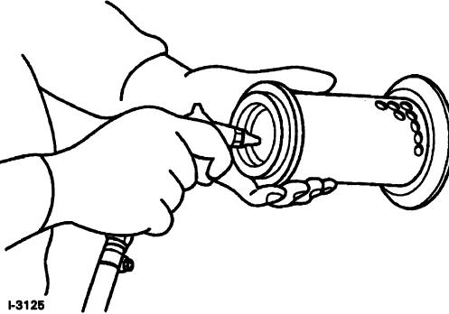
FIG. 163: Use the following procedure to clean the filter element:
• Using compressed air not to exceed 30 psi (200 kPa) from inside element, remove loose dirt, grass, chaff, etc. Be careful not to damage element pleats with air flow.
• If the element is coated with oil or soot:
1. Prepare solution of warm water and non-foaming detergent.
2. Soak element for 30 minutes.
3. Agitate element in solution until oil and soot are loosened.
4. Rinse element until rinse water is clear.
5. Allow element to completely dry. Do not dry by using compressed air or heat.
• After cleaning (or washing) element examine for pin holes, punctures, or tears. If element paper, canister or seal show any signs of physical damage, element must be replaced.
NOTE: Replace filter element which has already been washed 5 times.
Fuel System
Use only clean diesel fuel of correct grade. Introduction of water or dirt into fuel tank or other portion of fuel system can cause repeated plugging of fuel filter and possible injection pump and injector damage.
IMPORTANT: Do not tamper with injection pump or injector adjustment. Such tampering will spoil engine itself and / or cause severe engine damage. And warranty will not be covered for the machine with such tampering.
Fuel Filter
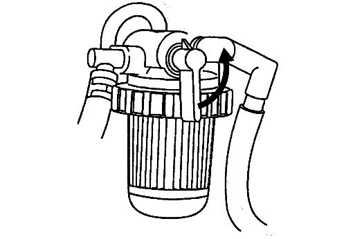
FIG. 164: Fuel filter assembly (1) is located at righthand side of engine and is used to strain impurities from fuel before fuel reaches injection pump. Fuel filter incorporates fuel cock (2) to aid in filter servicing and air-bleeding of fuel system.
Check filter bowl for accumulation of sediment or water and clean as required.
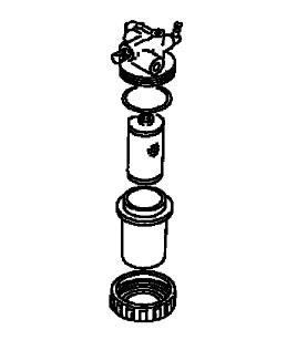
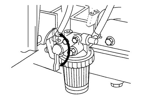
FIG. 165: To replace fuel filter element or clean sediment, turn fuel cock to OFF position (handle to front).
Carefully loosen ring nut (1) Remove nut, sediment bowl (2) and O-ring (4). Sediment bowl can be cleaned at this time. Pull downward on filter element (3) and discard. Examine small O-ring (5) in filter head and replace as necessary. Install new element, pushing upward until seated.
Install sediment bowl O-ring, and nut. Tighten nut and wipe up spilled fuel.
Air-Bleeding Fuel System
To bleed air from the fuel system:
• Fill the fuel tank.
• Turn the fuel cock to “ON”.
• Turn the main switch “ON”
FIG. 166: If the engine still fails to start, pressure injection line can be loosened where they attach to the injectors. Turn the engine over several times, until fuel spouts out, then tighten the lines and stop the engine.
NOTE: Normally, further air-bleeding is not required due to electric fuel pump operating when main switch in instrument panel is ON.
If engine will not start after several attempts, check fuel pump fuses (see “Electrical System”).
Fuel Tank Filler Cap
When fuel tank filler cap is removed, a hissing or popping noise may be noticed. This is due to cap design and is a normal condition. Do not alter cap or use unapproved replacement as fuel leakage may occur in event of tractor upset.
Throttle Lever
FIG. 167: Hand throttle lever should remain in position selected by operator. Through normal use, friction against lever may decrease, causing lever to move out of selected position. Turn adjusting nut (1) as required to retain throttle lever in position selected.
NOTE: Throttle lever friction adjustment is accessed by removing rear steering column cover.
Electrical System
Battery
FIG. 168: Battery (1) is located under engine hood in front of radiator. If battery requires only minor servicing or charging, it is recommended that hood side panels be removed to access battery.
When battery removal, electrolyte inspection or cable cleaning is necessary, front grille must be removed from tractor.
Keep top of battery clean and ensure cable connections are clean and tight. Debris on battery can cause discharge of battery and possible source of fire.
CAUTION: Batteries produce explosive hydrogen gas when charged. Keep all sparks and open flame away from battery.
When necessary to disconnect battery cables, always disconnect the grounded (-) cable first to prevent short circuits.
Batteries contain sulfuric acid electrolyte (fluid). Wear eye and face protection. If electrolyte comes in contact with skin or clothes, wash immediately. Contact a doctor if electrolyte is ingested or gets in eyes.
FIG. 169: Tractors are shipped with battery installed. If battery replacement should become necessary, disconnect negative (-) cable (1) first and then remove positive (+) cable (2). Loosen and remove battery securing clamp and carefully remove battery from tractor.
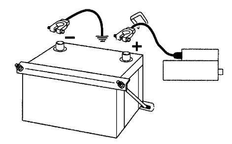
When installing battery, cable (2) connected to starter solenoid should be connected to positive (+) battery terminal first then cable (1) grounded to tractor frame can be connected to negative (-) battery terminal.
IMPORTANT: Do not reverse battery cable connections as severe electrical system damage will result.
NOTE: Make sure replacement battery is of identical size and equal capacity.
Never close or cover vent of battery.
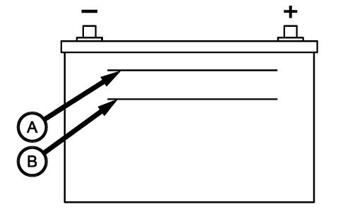
The battery is required the electrolyte inspection. Make sure that the electrolyte level is between upper limit (A) and lower limit (B). When the level is below lower limit, raise the level with distilled water.
WARNING:
NEVER disassemble battery. Batteries contains sulfuric acid electrolyte (fuild). Keep away from sparks or flames, which could cause explosion.
When charging battery from an external source, Set charging voltage below 16V. Set charging ampere below 1/10 of the battery capacity. Prevent overcharge. Battery temperature must not exceed 113°F (45°C).
When connecting and disconnecting battely cables, turn off power of battely charger. If you have any questions about the battely, consult your dealer.
If the battery performance become poor, the battery should be removed and recharged from an external source following battery charger instructions. Repeated battery charging may be due to a defect in tractor charging system and/or a defective battery.
IMPORTANT: Do not quick-charge the battery, or it may damage the battery and decrease its performance.
IMPORTANT: Charge the battery before the first use of this tractor.
IMPORTANT: When storing tractor for long period without operation, self discharge of battery will happen (especially in winter). If the tractor is stored for more than 1 month, the battery minus terminal should be disconnected.
When operating for the first time or after long term storage, check if the battery charge level is enough. (If measurement of battery voltage is available, check if the voltage is more than 12.5 V.) When the tractor is stored more than 2 months in summer or 3 months in winter, charge the battery.
IMPORTANT: When storing tractor for long period without operation, self discharge of battery will happen (especially in winter). If the tractor is stored for more than 1 month, the battery minus terminal should be disconnected.
When operating for the first time or after long term storage, check if the battery charge level is enough. (If measurement of battery voltage is available, check if the voltage is more than 12.5 V.) As the battery discharge even when it it not used, it should be charged every month.
Starting Switches
This tractor is equipped with a neutral-start system consisting of neutral switches and a relay. To start tractor, ALL the following is required:
Oparator seated on the seat.
Depress the clutch pedal (Mechanical and Synchro Transmission)
Forward / Reverse Lever in Neutral (Synchro Transmisson)
Do not depress the HST pedal. (HST model)
Sub shift lever set to neutral position. (HST model and SynchroTransmission)
Rear PTO Switch (Lever) in Off position
Never fail to install the seat with neutral switch.
NOTE: A seat safety switch is incorporated into system. The engine stops when operator leaves seat when either PTO is engaged and / or range shift lever is not in neutral.
WARNING: DO NOT bypass or modify the neutral switch. If the neutral start system does not operate properly, consult your dealer immediately.
Safety Switches
This tractor is equipped with a safety-start system consisting of safety switches and safety relay. To start tractor, ALL the following is required:
Gearshift lever must be in neutral position
PTO control switch must be OFF
Wiring / Fuse Arrangement
CAUTION: Keep all wiring connections clean and tight. Make sure wiring is correctly secured to prevent damage.
CAUTION: DO NOT alter wiring by adding “home-made” extensions or replacements. Doing so can eliminate fuse protection and / or eliminate safety features of the system.
CAUTION: Tractor is equipped with negative (-) ground system. Tractor metal parts provide many electrical connections. For this reason, all positive (+) circuits must be insulated to prevent “grounding” or short circuits and prevent possible fire.
CAUTION: DO NOT replace any fuse with a fuse of higher amperage rating. DO NOT use wire (or foil) to by-pass fuse protection. Fire can result.
If fuses blow repeatedly, examine electrical system for “grounded” or “shorted” circuits.
1 Main fuse box - Located on right side of the steering post.
Ref.AmpFunction
Left hand side of Fuse Box
110APTO
25AFuel Pump
310ACAB Power supply (AC)
415ATurn light, Winker
510AMater panel and Safety relay
Right hand side of Fuse Box
610AStarter and Key Stop Solenoid
715AWork Light*
820ABATT/Cabin power supply
915AHead Light
1015AHorn Parking Brake warning buzzer.
1115AHazard
1210ABrake Lamp
*Work light (rear) is an accessory.
2 Slow blow fuses - In-line fuses protect relevant circuit by melting when sustained heavy electrical load or short circuit is encountered, and feature a delayed action to prevent the current disruption when brief surges are encountered. The slowblow fuses are located on the right-hand side of the engine.
Ref.AmpFunction
140AStarter (Green)
240AMain Switch(Green)
340AAlternator Circuit (Green)
NOTE: Failure of the main circuit fuse is usually caused from incorrect polarity (such as reversed cables when using a booster battery). Failed fuse will not allow battery to be charged during normal operation.
IMPORTANT: Fuses are of specific amperage capacity for the circuit in which they are located. Do not replace fuses with unauthorized parts.
3 External power 12v / 50W
4 Rear work lamp connector 12v / 50w x 2 - This connection is for optional rear work lamps.
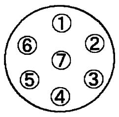
5 7 Pins socket - Provides electrical connection for trailer socket.
6 Seat switch connector
CLUTCH FREE-PLAY ADJUSTMENT
FIG. 172: Check clutch pedal free-play regularly and adjust as necessary. Correct clutch pedal free-play, A, is 20 to 40 mm (7 / 8 to 1-1 / 2”) when measured at the end of the pedal as shown.
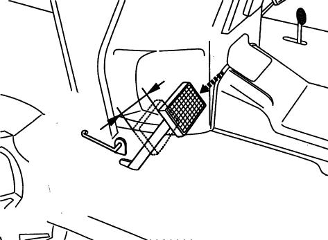
NOTE: Through use, clutch free-play will be reduced.
IMPORTANT: Correct free-play must be maintained to; reduce wear on clutch and release bearing, and allow complete disengagement when pedal is depressed.
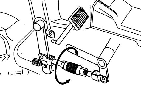
FIG. 173: To adjust clutch pedal free-play, loosen lock nut (1) (right-hand thread), and lock nut (2), (left-hand thread). Adjust turnbuckle (3) on linkage until free-play is correct. Lengthening linkage will increase free-play, shortening linkage will reduce free-play.
Secure by retightening lock nuts.
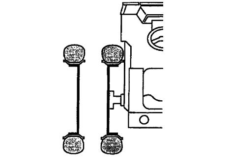
Brake Adjustment
FIGS. 174 & 175: Unlatch pedals and check freeplay of each brake pedal. Correct free-play, A, of each individual brake pedal is 40 to 50 mm (1-9 / 16 to 1-15 / 16”).
NOTE: Through use, free-play will increase and brake balance will be affected. Adjust and balance brakes before free-play is excessive.
FIG. 176: Loosen lock nut (1) (right-hand thread), and lock nut (2) (left-hand thread). Adjust turnbuckle (3) so free-play is correct for respective brake pedal. Repeat procedure for other brake so free-play in pedals is equal. Secure lock nuts against turnbuckles. When adjustment is complete, latch pedals together and operate tractor at low speed. Depress pedals. If tractor has tendency to “pull” to 1 side, slight readjustment of 1 brake is required. Make sure lock nuts are secured when brake adjustment is complete. Check operation of parking brakes after adjustment is made.
CAUTION: Brakes must be adjusted evenly to permit equal braking action at both rear wheels when brake pedals are latched together.
Adjustment of parking brake lever
FIGS. 177 & 178:
1. After the adjustment of brake, adjust the parking brake by turn buckle (A), in order to apply the brake with 2 knock from full down position.
2. If 1 side brake is applied, adjust the turn buckle (B) in order to apply the L & R both brake same time.
NOTE: Turn buckle (B) are positioned both side of transmission.
Neutral start system
WARNING: DO NOT bypass or modify the neutral switch system. If the switch system does not operate properly, consult your dealer immediately.
This tractor is equipped with a neutral start system consisting of neutral switches and a relay. To start the tractor, all the following is required:
Oparator seated on the seat.
Depress the clutch pedal(Mechanical and SynchroTransmission)
• Forward / Reverse Lever in Neutral(Synchro Transmisson)
Do not depress the HST pedal.(HST model)
Sub shift lever set to neutral position.(HST model and SynchroTransmission)
• Rear PTO Switch(Lever) in Off position
Never fail to install the seat with neutral switch.
NOTE: A seat switch is incorporated into the system. The engine stops when the operator leaves the seat when either the PTO is engaged and / or shift lever is not in neutral.
NOTE: All transmission levers must be in neutral.
Wiring / Fuse Arrangement
CAUTION: Keep all wiring connections clean and tight. Make sure wiring is correctly secured to prevent damage.
Do not alter wiring by adding home-made extensions or replacements. Doing so can eliminate fuse protection and / or eliminate safety features of the system.
Tractor is equipped with negative (-) ground system. Tractor metal parts provide many electrical connections. For this reason, all positive (+) circuits must be insulated to prevent grounding or short circuits and prevent possible fire.
Do not replace any fuse with a fuse of higher amperage rating. DO NOT use wire (or foil) to by-pass fuse protection. Fire can result.
If fuses blow repeatedly, examine electrical system for grounded or shorted circuits.
WHEELS & TIRES
Examine wheels and tires periodically for correct inflation pressures, tight wheel bolts, and any physical damage that may be a detriment to tractor operation and operator safety. Correct condition prior to tractor operation.
TABLE 16: Tire inflation pressures
Tire Inflation Pressures
FIG. 179: Maintaining correct tire pressure will help insure tire long life. If tires have deep scratches, cuts or punctures, the respective tire should be repaired or replaced by qualified personnel as soon as possible.
IMPORTANT: If necessary to replace any tire(s), ensure original tire size is used. This is particularly true on 4WD models to ensure correct amount of front axle overspeed (or “lead”) is maintained.
NOTE: It will be required to limit the angle of swing with stopper when tractor with center ROPS (A-type) equipped the “7-14” size tires. (Except center ROPS specifications.)
Wheel Bolt Tightening Torque
FIG. 180: Periodically check all wheel bolt torques. Correct bolt torques:
Front Wheel Bolts (1)...................... 7 ft.-lbs. (102 N•m)
Rear Wheel Bolts (2) .................. 120 ft.-lbs. (163 N•m)
CAUTION: Correct wheel bolt torque must be maintained. Installation of front or midmounted implements (ex; loaders, mowers) impose increased loads and require frequent checking of wheel bolts.
Front Wheel Alignment
FIG. 181: Correct “toe-in” dimensions of front wheels (A minus B) are as follows:
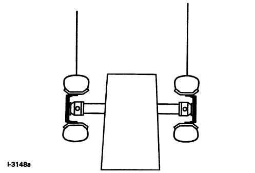
4WD.............................................. 2-6 mm (0.08-0.24”)
To adjust, loosen lock nuts (1) and adjust tie rod length by turning turnbuckle (2). Adjust each side evenly. Ball joints must move freely after lock nuts are tightened.
NOTE: Measure toe-in from tire center to tire center at a point halfway up on face of each tire.
Front Wheel Spacing
FIG. 182: Front 4WD Wheels - Ag tires, turf tires cannot be reversed.
: Available on only tractor with center
(Atype) and joystick (J-type).
NOTE: Wide type front axle is equipped with only center ROPS (A-type) and joystick (J-type).
Rear Wheel Spacing
FIG. 183: To reverse entire wheel and tire assembly
- Raise both rear tires of tractor. Remove bolts securing both rear wheel assemblies to rear axle hubs and switch wheel assemblies to opposite sides of tractor.
CAUTION: Rear wheels are heavy. Use care when moving. Make sure tractor is blocked securely.
Tighten all wheel bolts securely and recheck after short period of operation.
NOTE: Agricultural lug-type tires must always be installed so when viewed from the rear, the “V” pattern of the tread points upward.
TABLE 18: Rear tire tread setting
Tractor Type
Tires Tire Location Size Setting mm
AG Rear 12.4-161115
AG Rear 9.5-22900
TH4295
TH4335
TH4365
AG Rear 9.5-24900
AG Rear 11.2-241030
Turf Rear 315 / 80D-16965
Turf Rear 13.6-161000
: Available on only tractor with center ROPS (Atype) and joystick (J-type).
Steering Free-Play
FIG. 184: Steering should be checked for excessive looseness, as indicated by steering wheel free-play. Maximum free-play (1) is approximately 30 mm to 60 mm (1-1 / 4 to 2-3 / 8”) when measured at outside of steering wheel rim.
Excessive free-play can be caused by:
• Loose or worn ball joints
• Worn or damaged steering column shaft or universal joints
• Worn or damaged power steering unit
• Air in the steering system
CAUTION: Excessive steering free-play must be corrected before use. Contact your dealer.
Front Axle End-Float
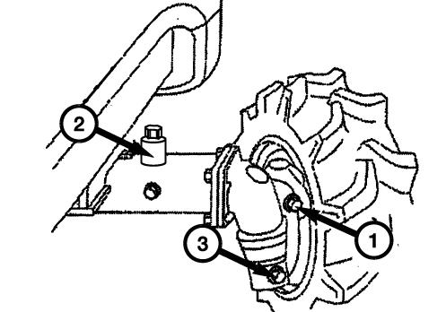
FIG. 185: Fore and aft play of front drive axle (1) in the supports should be 0.1 to 0.3 mm (0.004 to 0.012”). End-float is measured with axle raised off ground. Loosen lock nut (2) and turn adjusting bolt (3) as needed to achieve correct measurement. Tighten lock nut.
NOTE: Excessive end-float will cause noise. This noise will be more pronounced when using 4WD.
Clutch Housing Plug
FIG. 186: The plug (1) should be removed from bottom of clutch housing once a year. Any oil leakage from engine rear crankshaft seal and / or transmission input will be indicated by oil draining through hole. Contact your dealer if oil leakage is evident.
Torque Chart
TABLE 21: All fasteners should be tightened in accordance with torque chart unless a specific torque value is indicated in relevant maintenance information.
Storage
FIG. 187: If tractor is to be stored for extended periods, such as off-season non-use, certain measures should be taken for its preservation during such periods. These measures will vary according to geographical area and storage season.
Replace engine oil and filter. Operate at low idle 5 minutes to lubricate parts.
Lubricate all grease fittings and lightly oil control linkage pivots.
Detach implements.
Store tractor in enclosed area, if possible, for protection from weather.
If tractor cannot be placed in an enclosed area, use some sort of cover and cover exhaust pipe to prevent entrance of rain or snow.
Block up tractor to remove weight from tires and to protect tires from oily or damp floor.
Raise and lock 3-point lift linkage in up position by turning lowering rate control knob (1) fully clockwise.
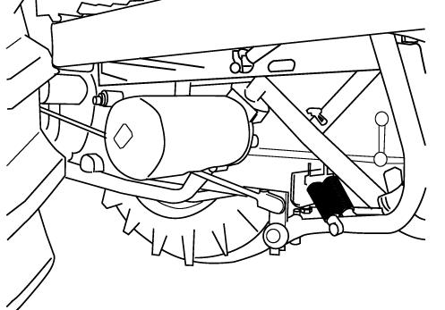
FIGS. 188 & 189: Fill fuel tank to prevent condensation from forming on inside of tank. Turn filter cock (1) to OFF position (handle to front). Remove battery and store in cool dry place. Maintain charge during storage period.
If tractor is stored during cold weather season insure that anti-freeze is adequate. Alternatively, radiator and engine block may be drained.
Check with your diesel fuel supplier on the availability of a diesel fuel additive to place in the fuel system during storage period.
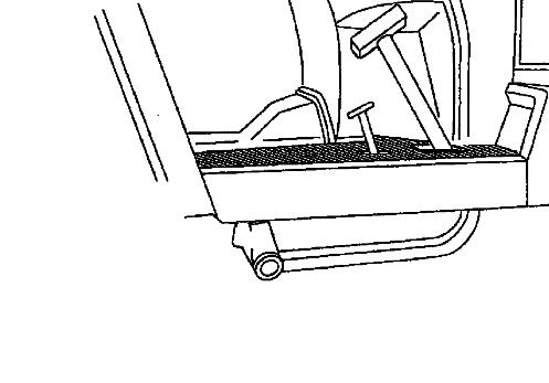
Depress clutch pedal (2) and secure in the disengaged position with hook (3) to prevent seizure during long periods of tractor storage. Touch up scratches with paint. At the end of storage period:
• Perform appropriate lubrication and maintenance before placing tractor back in service.
• Conduct full pre-start inspection. Make sure all controls operate correctly.
• Allow engine to idle approximately 30 minutes. Check for leaks and repair as required.
Washing Of The Machine
Wash the macine periodically. Carefully wash the area where mud spatters easily such as fender inner part.
CAUTION: If you use high pressure washer, be sure to use in accordance with this operator’s manual and safety label of washer. In case of irregular use, it may cause personal injury and damage to the machine.
CAUTION: Set the nozzle of hose ‘spread’ and keep the distance more than 60 cm in order to avoid damage to the machine. Especially, be care for not to hit the water to electrical parts and label.
Unsuitable washing may cause the following accidents;
1. Fire as a result of short circuit or the damage to the electrical parts.
2. Oil leakage as a result of the damage to the hydraulic hose.
3. Damage to the machine.
(1) Label is came off.
(2) Accident occurs by the damaged electrical parts, engine, radiator, and interior.
(3) Rubber parts (tire, seal) and resin parts are damaged.
(4) Paint is came off.