INTRODUCTION BRAKE SYSTEM, GENERAL This section has a description and the service procedures for the brake systems. The service brake system includes the following parts: master cylinder, brake shoes, wheel cylinders, pedal and linkage. See FIGURE 1. The parking brake includes the pedal, linkage and cables to operate the service brake shoes. See FIGURE 9. Some units have an additional seat brake as shown in FIGURE 11. This seat brake is connected to the armature of the traction motor.
Master Cylinder
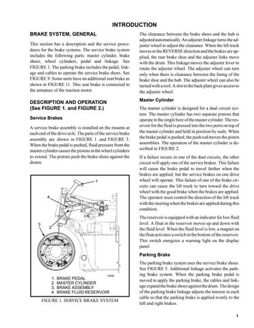
DESCRIPTION AND OPERATION (See FIGURE 1. and FIGURE 2.) Service Brakes A service brake assembly is installed on the mounts at each end of the drive axle. The parts of the service brake assembly are shown in FIGURE 1. and FIGURE 3. When the brake pedal is pushed, fluid pressure from the master cylinder causes the pistons in the wheel cylinders to extend. The pistons push the brake shoes against the drums.
1
4
3
The clearance between the brake shoes and the hub is adjusted automatically. An adjuster linkage turns the adjuster wheel to adjust the clearance. When the lift truck moves in the REVERSE direction and the brakes are applied, the rear brake shoe and the adjuster links move with the drum. This linkage moves the adjuster lever to rotate the adjuster wheel. The adjuster wheel can turn only when there is clearance between the lining of the brake shoe and the hub. The adjuster wheel can also be turned with a tool. A slot in the back plate gives access to the adjuster wheel.
The master cylinder is designed for a dual circuit system. The master cylinder has two separate pistons that operate in the single bore of the master cylinder. The reservoir for the fluid is pressed into the two ports on top of the master cylinder and held in position by seals. When the brake pedal is pushed, the push rod moves the piston assemblies. The operation of the master cylinder is described in FIGURE 2. If a failure occurs in one of the dual circuits, the other circuit will apply one of the service brakes. This failure will cause the brake pedal to travel farther when the brakes are applied, but the service brakes on one drive wheel will operate. This failure of one of the brake circuits can cause the lift truck to turn toward the drive wheel with the good brake when the brakes are applied. The operator must control the direction of the lift truck with the steering when the brakes are applied during this condition. The reservoir is equipped with an indicator for low fluid level. A float in the reservoir moves up and down with the fluid level. When the fluid level is low, a magnet on the float activates a switch in the bottom of the reservoir. This switch energizes a warning light on the display panel.
2
Parking Brake
1. 2. 3. 4.
12836
BRAKE PEDAL MASTER CYLINDER BRAKE ASSEMBLY BRAKE FLUID RESERVOIR
FIGURE 1. SERVICE BRAKE SYSTEM
The parking brake system uses the service brake shoes. See FIGURE 5. Additional linkage activates the parking brake system. When the parking brake pedal is moved to apply the parking brake, the cables and linkage expand the brake shoes against the drum. The design of the parking brake linkage adjusts the tension in each cable so that the parking brake is applied evenly to the left and right brakes. 1