INTRODUCTION GENERAL
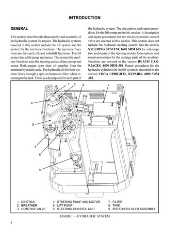
the hydraulic system. The description and repair procedures for the lift pump are in this section. A description and repair procedures for the electro-hydraulic control valve are covered in this section. This section does not include the hydraulic steering system. See the section STEERING SYSTEM, 1600 SRM 605 for a description and repair of the steering system. Descriptions and repair procedures for the carriage parts of the auxiliary functions are covered in the section REACH CARRIAGES, 4500 SRM 384. Repair procedures for the hydraulic cylinders for the lift system is described in the section VISTA UPRIGHTS, REPAIRS, 4000 SRM 383.
This section describes the disassembly and assembly of the hydraulic system for repairs. The hydraulic systems covered in this section include the lift system and the system for the auxiliary functions. The auxiliary functions are the reach, tilt and sideshift functions. The lift system has a lift pump and motor. The system for auxiliary functions uses the steering and auxiliary pump and motor. Both pumps draw their oil supplies from the common hydraulic tank. The hydraulic oil for both systems flows through a spin on hydraulic filter when returning to the tank. There is a description for each part of 1
2
3
4
9
8
7 6
5
1. DIPSTICK 2. BREATHER 3. CONTROL VALVE
4. STEERING PUMP AND MOTOR 5. LIFT PUMP 6. STEERING CONTROL UNIT
7. FILTER 8. TANK 9. BREATHER/FILLER ASSEMBLY
FIGURE 1 – HYDRAULIC SYSTEM 1
