MOUNTING BOLTS (COMMERCIALLY AVAILABLE)
Tiller handle S type only:
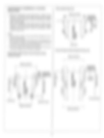
INSTALLATION 1. Mark two installation hole points (four in total) on the transom of the boat at the right and left mirror image positions with the transom center line between (Except tiller handle S type). Mark one installation hole point (two in total) on the transom of the boat at the right and left mirror image positions with the transom center line between (Tiller handle S type only).
+ TRANSOM
4
I
NOTE: Do not drill a hole in the wood block attached to the transom of the boat. Be sure that the upper bolt holes are not located above the position shown in the drawing (more than 25 mm/l.O in from top of the transom board). Drill the lower bolt holes so that mounting bolts contact the upper end of the stern bracket.
BOARD TOP
\
08.5 mm
Power tilt type and Gas-assisted tilt type only:
Except Tiller handle S type, Power tilt type and Gasassisted tilt type:
244 mm (9.6 in)
*
4
244 mm (9.6 in) I
i------------i
rn
I I I
TRANSOM BOARD TOP
I I
r
TRANSOM BOARD TOP
I
N
4
4
-6E
57mm (2.2 in)
E
v)
0 N If
51 mm 1(2.0 in) 0 10.5 mm
L!
I
26 mm (1.0 in)
128 mm (5.0 in)
-
4
252 mm (9.9 in)
5


