11 minute read
CONTROL CABLE INSTALLATION

from Honda Outboard Motor BF15D BF20D Set-up Installation & Pre-delivery Manual 96ZY010 - PDF DOWNLOAD

CONTROL BOX SIDE I 5 x 25 rnrn TAPPING SCREW
1. Remove the two 5 x 25 mm tapping screws and housing cover C.
2. Screw the lock nuts and eye ends more than 8 mm (0.3 in) onto the thread of the control cables and tighten the lock nuts securely to hold the pivots. Apply marine grease to the hole of the eye end.
More than 8 rnrn (0.3 in)
LOCKNU< /
EYE END (MARINE GREASE)
3. Install the shift control cable by aligning the groove of the control cable with the cable guide plate. Then connect the eye end to the shift arm pin using the washer and 6 rnrn lock pin.
4. Install the cable clamp spacer and throttle control cable by aligning the groove with the cable guide plate. Then connect the eye end to throttle arm pin using the washer and 6 mm lock pin.
NOTE: Install the washer on the lock pin side.
HOUSING COVER C
THROTTLE CONTROL CABLE
BLE CLAMP SPACER CONTROL CABLE
5. Reinstall the housing cover C and tighten the 5 x 25 mm tapping screws.
Torque: 2 Nm (0.2 kgf-rn, 1.4 Ibf.ft)
THROTTLE CONTROL CABLE
BLE CLAMP SPACER
THROTTLEARM
SHIFT ARM
CABLE
CABLE GUIDE
EYE END
6 rnrn LOCK PIN
Outboard Motor Side
a. CONTROL CABLE
NOTE:
After installing the control cable to the remote control box, install the control cable to the outboard motor. Set the control lever in the "F" (FORWARD) full throttle position and the fast idle lever in the "Release" position, then connect the control cable.
1. Remove the engine cover
2. Remove the 5 mm screw-washer and remove the R. engine under cover outside about 10 mm (0.4 in). Take care not to damage the cover moving too much.
3. Temporarily install the lock nut and shift pivot on each cable.
LOCK PLATE (2)
R. ENGINE UNDER COVER
CONTROL CABLE PLATE
THROlTLE CONTROL CABLE
4. Pass the two cables through the gap in the control cable plate to the engine side, then pass the two cables through the slit in the oil case grommet A.
5. Set the groove of each control cable in the cutout in the control cable plate, and set the oil case grommet A in the groove of the R. engine under cover.
NOTE:
The throttle control cable and the shift control cable use the same cables and they look the same. Move the remote control lever to identify each cable and place the throttle control cable upside.
6. Position the shift link arm in the "F" (FORWARD) position, and adjust the position of the shift link arm and the shift control cable. Loosen the lock nut of the control cable and turn the shift pivot in or out to align the pivot pin with the shift link arm hole.
CLICK SPRING FORWARD POSiTiON
THROTTLE REMOTE ARM
SHIFT LINK ARM \
THROTTLE CONTROL CABLE / SHIFT CONTROL CABLE
NOTE:
The throttle remote arm lock plate and the shift link arm lock plate are installed in the opposite direction. Be careful of the direction when install them.
THROTTLE REMOTE ARM LOCK
SHIFT LINK ARM \ SHIFT SHAFT
7. Set the throttle arm in the full throttle position, and adjust the throttle remote arm and the throttle control cable.
8. Tighten each cable lock nut. Be careful not to kink the cables.
9. Install the pivot pins into the shift and throttle arm holes and lock with the lock plates.
SHIFT PIVOT
10.Operate the control lever to check for proper operation.
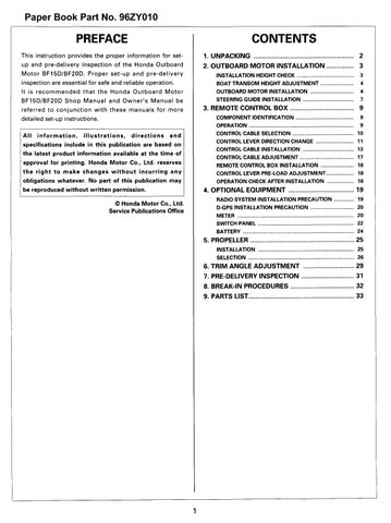
Control Box Wire Harness Connection
1. Remove the 5 mm screw-washer and move the L. engine under cover outside about 10 rnrn (0.4 in). (Do not move the L. engine under cover excessively as the cover can be damaged.)
5 mm SCREW-WASHER
L. ENGINE UNDER COVER 6P WHITE 4P WHITE CDI BRACKET CONNECTOR CONNECTOR
TIE WRAP BAND
WIRE HARNESS
OIL CASE HARNESS
GROMMET B CLIP BAND
2. Move the upper half of the oil case grommet B to a side and insert the control box wire harness through the slit. Return the oil case grommet B to the original position.
3. Set the control box wire harness in the position where the tie-wrap band gets in contacts with the inner side of the oil case grommet B. Secure the cable with the harness clip band inserted in the cable plate.
4. Cut the end of the harness clip band so the length at the end is 5 mrn or below.
5. Connect the cable connectors to the corresponding 6P white connector and the 4P white connector of the engine side wire harness, then install to the CDI bracket.
6. Open the starter magnetic switch harness band. Secure the control box wire harness together with the starter cable using the harness band.
7. Pass the L. engine under cover in the original place and tighten the 5 mm screw-washer securely.
POWER TILT TYPE:
OIL CASE GROMMET B CONTROL BOX WIRE . HARNESS SLITS
ARNESS CLIP BAND
HARNESS
STARTER CABLE
POWER TILT TYPE:
EXCEPT POWER TILT TYPE: Engine side
ONTROL BOX
WIRE HARNESS
RNESS CLIP BAND
POWER TILT WIRE HARNESS
After securing the cable, the band end length must be 5 mm or below. Cut the excess. or below. Cut the excess. CABLE PLATE c View from oil case grommet B side >
Control Cable Adjustment
NOTE:
Check that the throttle cable and the shift control cable are set in the correct position. If not, adjust the cables with the following procedure.
Throttle Cable
1. Remove the throttle control cable from the throttle remote arm.
2. Loosen the recessed bolt on the throttle remote arm.
3. Pull the throttle rod to the right to make carburetor throttle lever fully-open, and push the throttle remote arm to the right against the stopper.
4. Tighten the recessed bolt securely.
THROTTLE STOP SCREW CARBURETOR
TTLE REMOTE ARM
Shift Control Cable
1. Remove the shift control cable from the shift link arm.
2. Set the shift shaft in the "Forward" position and the control lever in the "F" (FORWARD) position.
3. Check the installation points of the shift link arm and shift control cable. If the installation points are not aligned, adjust the shift pivot first, then install the shift link arm and shift control cable. (See step 6 on page 15.)
4. Set the control lever of the control box in the "F" (FORWARD), "N" (NEUTRAL), and "R" (REVERSE) positions respectively, and be sure that the shift shaft is in the corresponding positions of "Forward", "Neutral" and "Reverse", too.
Shift Shaft Position
Forward (F)
Neutral (N)
Stopper
5 x 8 mm RECESSED BOLT
5. Install the throttle remote arm and throttle control cable with the control lever of the control box in the "F" (FORWARD) full throttle position and the fast idle lever in the release position.
If the installation points are not aligned, install after adjusting the shift pivot of the throttle control cable. (See step 7 on page 15.)
6. Set the control lever in the full throttle position and "N" (NEUTRAL) position and be sure that the carburetor is in the full open and full close positions respectively.
Reverse (R)
5. If the shift shaft position is not in place where it should be, repeat the step 3 and 4.
6. Move the control lever and check that the shift shaft moves smoothly and securely.
7. Set the R. engine under cover securely, and tighten it with the 5 mm screw-washer.
8. Install the engine cover securely.
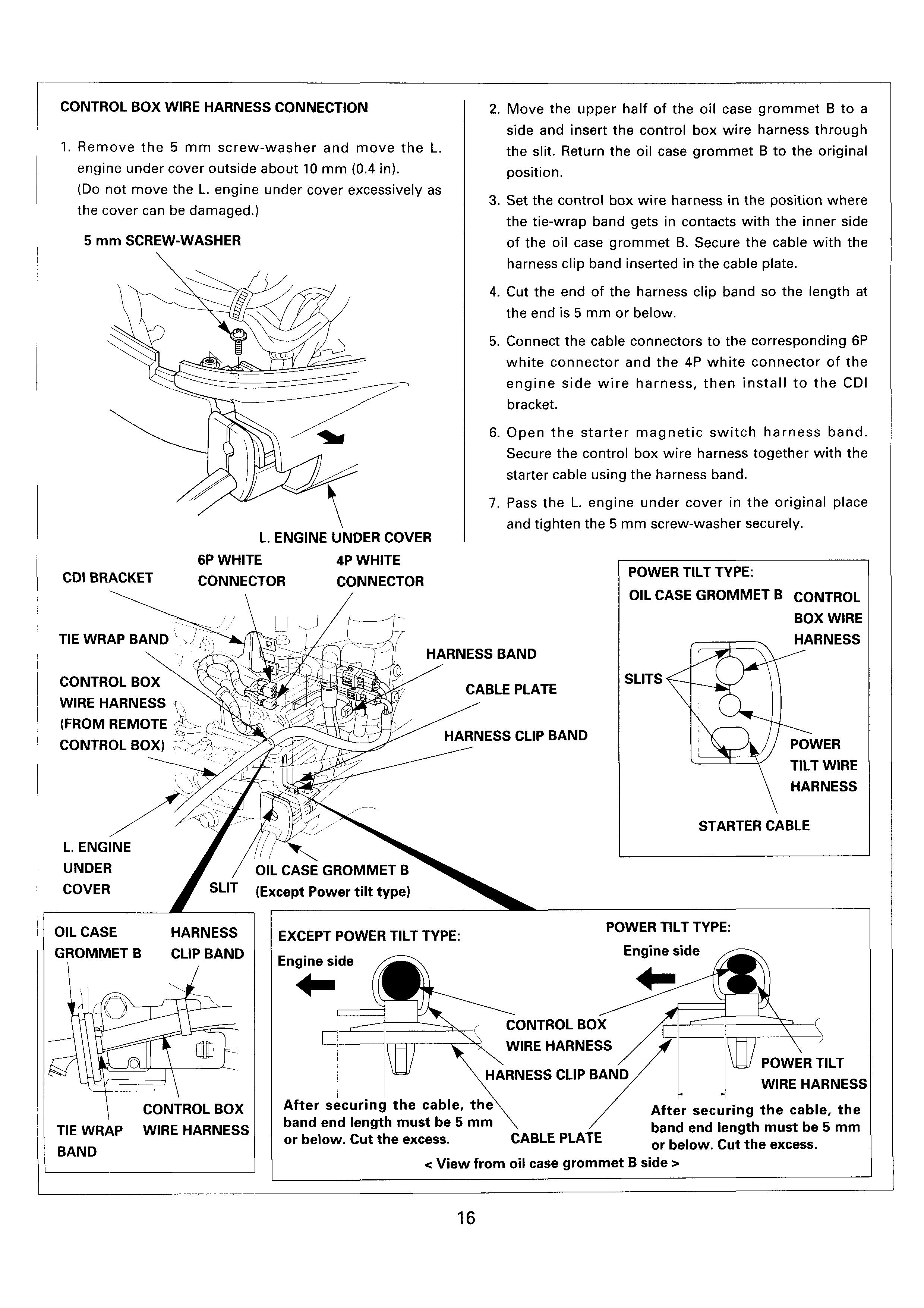
Remote Control Box Installation
NOTE:
After the control cable installation and adjustment, install the remote control box to the hull. Install the remote control box at the selected mounting location using the supplied parts. Set the control lever to the "N" (NEUTRAL) position when installing the remote control box.
Operation Check After Installation
NOTE:
Check whether the control cable is adjusted properly and there is no twist or bend in the cable. Check the control lever for smooth operation and check the control cable for smooth movement without restriction.
1. Set the control lever in the "F" (Forward) position (approx. 30") and check whether the shift shaft is in the forward position.
2. Set the control lever in the "F" (Forward) full open position and check whether the carburetor throttle lever is in the full open position.
3. Return the control lever to the "N" (Neutral) position and check whether the carburetor throttle lever is in the full close position.
4. If the carburetor throttle lever does not move to the full open and/or full close position, adjust the throttle control cable again.
CONTROL LEVER PRE-LOAD ADJUSTMENT
1. The control lever pre-load can be adjusted by turning the friction adjustment bolt at the front of the remote control box.
2. Turning the bolt clockwise will increase the pre-load, turning it counterclockwise will decrease.
NOTE:
Do not turn the adjusting bolt more than necessary.
If the carburetor throttle rod and throttle control cable had been adjusted properly, the carburetor throttle lever should automatically move to full open/full close position accordingly by setting the control lever in the fully open/fuII close position. If the carburetor throttle lever is not in the proper position, adjust as follows.
-1. Remove the two 5 x 12 mm screws and remove the fast idle lever.
-2. Remove the five 5 x 25 mm self-tapping screws and remove the control housing B.
-3. Remove the two 5 x 25 mm tapping screws and remove the housing cover C.
5x25mm 5 x 12 mm 5 x 25 mm TAPPING TAPPING
SCREW (2)
-4. Set the control lever in the throttle full open position.
-5. Loosen the lock nut on the link joint bracket, and adjust by turning the stopper bolt to bring the carburetor to full open.
4. OPTIONAL EQUIPMENT
Radio System Installation Precaution
NOTE:
Radio wave is strong that it may damage the outboard motor. Carefully follow the installation instruction.
Keep the antenna and the radio unit at least 50 cm (1.6 ft) away from the outboard motor, control cable and remote control box.
Do not install the antenna cord and control cable tied UP.
Select a radio with its output power less than 10 W. GOOD
-6. Tighten the lock nut. Install the housing cover c, control housing B and the fast idle lever.
AtFst 50cm (1.6ft) RADIO UNIT NO GOOD
Radio unit too close to remote control box and control cable.
Install antenna cable and trol cable together. emote control cable near
Install antenna near outboard motor.
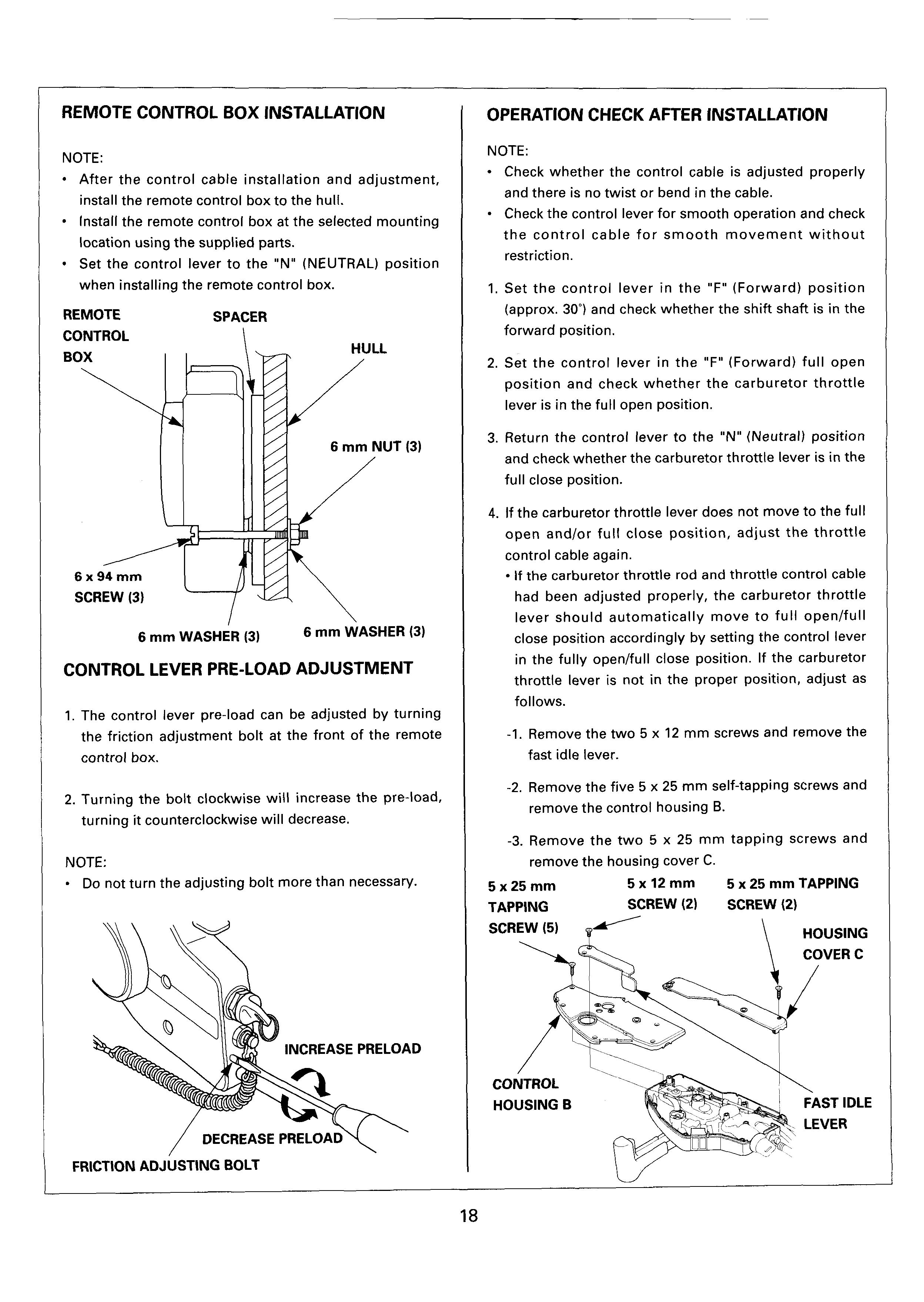
D-GPS INSTALLATION PRECAUTION
NOTE:
Carefully follow the installation instruction when install a D-GPS.
1. Keep the D-GPS unit and antenna at least 3 m (10 ft) away from the outboard motor.
2. Be sure to connect the ground system to the boat.
Meter Installation
Meters and other instruments should be installed on the dash board. If any other location is selected, it will be necessary to use a mounting plate with a thickness of 211 mm (0.04 - 0.44 in).
NOTE:
If the mounting plate thickness exceeds 11 mm (0.44 in), the bracket must be modified accordingly (hour meters up to a thickness of 8 mm can be installed). Tighten the mounting nuts evenly on both sides.
OPENING SIZE
Type Opening Diameter
Tachometer 80.5 rnm (3.17 in)
Hour Meter 50.4 mrn (1.98 in)
Voltmeter 54.0 mm (2.13 in)
MOUNTING PANEL
THICKNESS: 2 - 11 mm (0.04 - 0.44 in)
Meter Wire Harness Connection
Route and connect the wire harness properly as shown in the wiring diagram. Use the genuine Honda wire harness and modify it if necessary.
NOTE:
Stake the lead wire against the terminal securely using the special tool.
Use the 1.25 mm dia. (AWG #6) lead wire to put them together. Solder the joint section and protect it by wrapping with a piece of insulation tape.
CAUTION:
First, check whether the wire harnesses are connected as shown in the wiring diagram, then connect the battery and turn the power switch ON to check for proper condition of the electrical parts and wire harness.
Wrap the free terminal with a piece of vinyl tape or equivalent to insulate them securely.
Before reconnecting connectors, check them carefully to make sure that their terminals are not bent, exposed, or disconnected.
If a terminal is oxidized or corroded, remove the oxidation or corrosion with nonconductive plastic scrub pad and contact cleaner before reconnecting it. Be sure to reconnect connectors by inserting them fully into their receptacles. Check locking connectors to be sure that locking devices are locked in place securely.
Check insulators to make sure they surround their connectors completely. Do not fold up the mouths of insulators.
Before reconnecting wire connectors, check them to make sure that the covers are not torn or broken, and that the gaps of female terminals are not overly expanded and loose.
MOUNTING NUT
Do not break the coverings of wire harness. If the covering of wire harness is broken, either repair it with electrician's tape, or replace it.
Meter Wiring Diagram
Wrap the free terminals with a piece of vinyl tape and hold them onto the wire harness as shown.
Secure the free terminals on the harness by taping them around to prevent them from contacting any neighboring parts and the resulting short-circuit.
(Y/Bu connector is not used)
Bliy+ BI/Y - TO CONTROL BOX WIRE GrpGr- METER WIRE HARNESS A - - ’ HARNESS
Wrap the terminal with a piece of vinyl tape.
Switch Panel
If your boat is equipped with a Binnacle or Flash mounting type remote control box, prepare the switch panel as follows to install the electrical parts and switches.
Part name
Ignition switch
Emergency stop switch
Indicator lamp
Buzzer
Power tilt switch (commercially available)
Control box wire harness
EMERGENCY
IGNITION SWITCH
WARNING BUZZER
SWITCH PANEL (Of your own making)
POWER TILT SWITCH
RECOMMENDED SHAPE
Use 3 mm (0.12 in) thick aluminum or stainless steel plate.
45 mm k(1.8 in) 9
INDICATOR LAMP
30 rnm in) 4 CORNERS)
INDICATOR LAMP
+ 101 mm (4.0 in) 4
INSTALLATION
IGNITION SWITCH
Drill the holes in the panel so that the switch can be installed with the drain hole facing down.
+~0 25 mm (1.0 in)
LOCK NUT
5 N.m (0.5 kgfm, 3.6 Ibf.ft)
EMERGENCY STOP SWITCH
WATER DRAIN HOLE
Drill the holes in the panel so that the switch can be installed with the drain hole facing down.
0 16 mm (0.6 in)
+7EMERGENCY STOP SWITCH
WARNING BUZZER
Prepare the bracket of the dimensions shown, and install the warning buzzer with the drain hole toward down.
BRACKET
Use 1 mm (0.04 in) (0.08 in), ,I7 mm (0.7 in) thick aluminum or stainless steel plate. /
2 mm
WATER DRAIN HOLE
POWER TILT SWITCH INSTALLATION
Use a commercially available toggle switch.
Installation hole: 12 mm in diameter
Connecting terminal: JIS PA
SWITCH WIRE HARNESS CONNECTION
Connect the wire harness as per the wiring diagram shown on the following page.
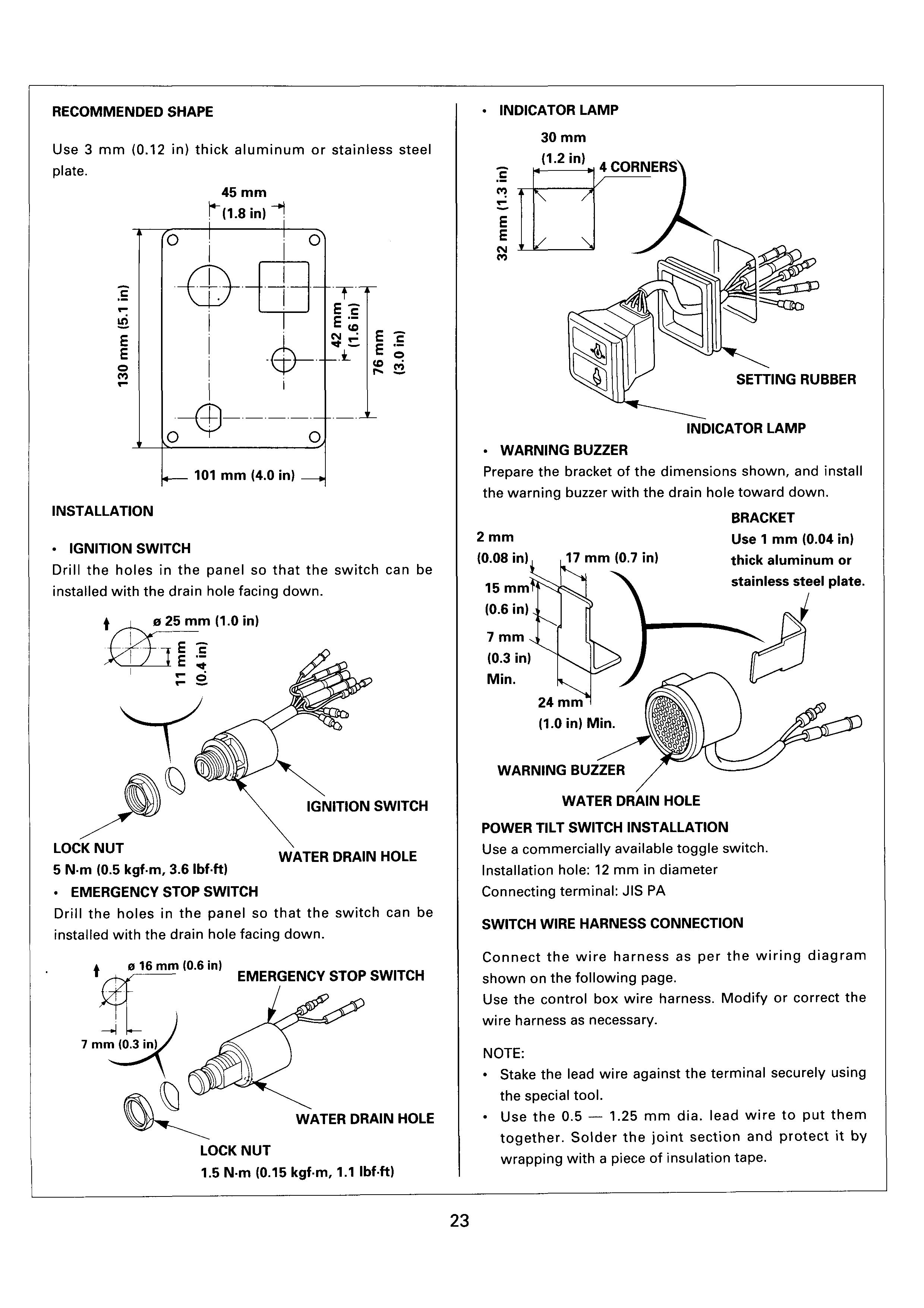
Use the control box wire harness. Modify or correct the wire harness as necessary.
NOTE:
Stake the lead wire against the terminal securely using the special tool.
Use the 0.5 - 1.25 mm dia. lead wire to put them together. Solder the joint section and protect it by wrapping with a piece of insulation tape.
Switch Panel Wiring Diagram
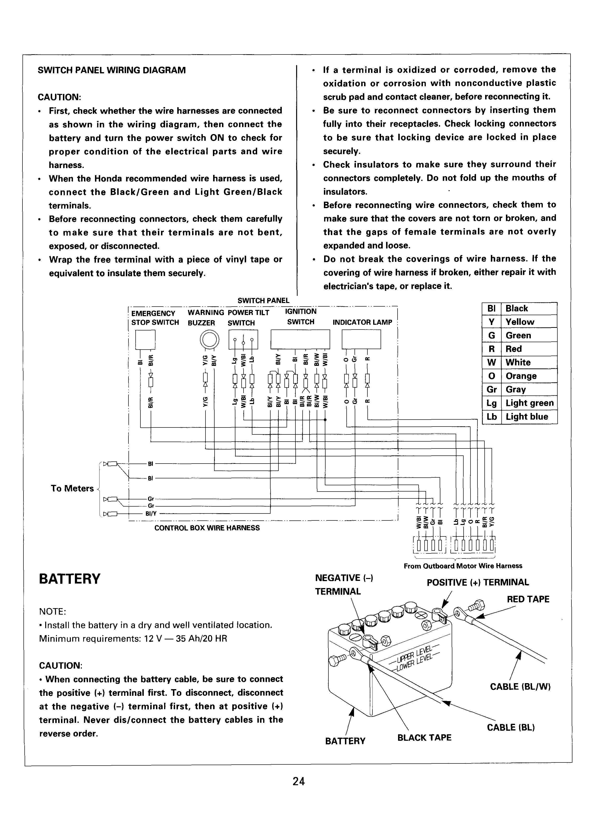
CAUTION:
First, check whether the wire harnesses are connected as shown in the wiring diagram, then connect the battery and turn the power switch ON to check for proper condition of the electrical parts and wire harness.
When the Honda recommended wire harness is used, connect the Black/Green and Light Green/Black terminals.
Before reconnecting connectors, check them carefully to make sure that their terminals are not bent, exposed, or disconnected.
Wrap the free terminal with a piece of vinyl tape or equivalent to insulate them securely.
If a terminal is oxidized or corroded, remove the oxidation or corrosion with nonconductive plastic scrub pad and contact cleaner, before reconnecting it. Be sure to reconnect connectors by inserting them fully into their receptacles. Check locking connectors to be sure that locking device are locked in place securely.
Check insulators to make sure they surround their connectors completely. Do not fold up the mouths of insulators.
Before reconnecting wire connectors, check them to make sure that the covers are not torn or broken, and that the gaps of female terminals are not overly expanded and loose.
Do not break the coverings of wire harness. If the covering of wire harness if broken, either repair it with electrician's tape, or replace it.
To Meters
Battery
NOTE:
Install the battery in a dry and well ventilated location.
Minimum requirements: 12 V - 35 Ah/20 HR
CAUTION:
G
Green R Red W White 0 Orange