-
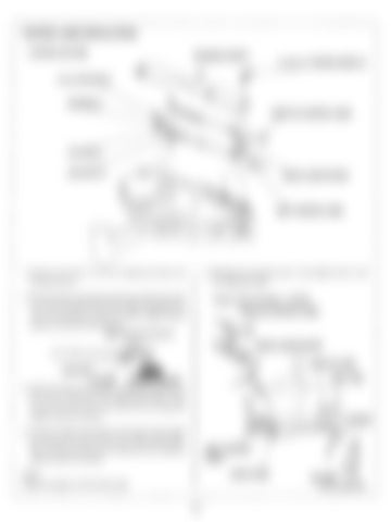
CONTROL CABLE INSTALLATION CONTROL BOX SIDE
HOUSING COVER C
I
5 x 25 rnrn TAPPING SCREW (2)
w
THROTTLE CONTROL CABLE
BLE CLAMP SPACER
CONTROL CABLE
5. Reinstall the housing cover C and tighten the 5 x 25
1. Rem ov e t h e t w o 5 x 25 m m t a p p i n g s c re w s a n d housing cover C.
m m tapping screws.
2. Screw the lock nuts and eye ends more than 8 m m (0.3 in) onto the thread of the control cables and tighten the
Torque: 2 N m (0.2 kgf-rn, 1.4 Ibf.ft) THROTTLE CONTROL CABLE
lock nuts securely to hold the pivots. Apply marine grease t o the hole of the eye end.
More than 8 rnrn (0.3 in) BLE CLAMP SPACER
LOCKNU<
/
THROTTLEARM SHIFT ARM
EYE END (MARINE GREASE) 3. Install the shift control cable by aligning the groove of the control cable w i t h th e cable g u i d e plate. Then connect t he eye end t o th e shift a rm p i n using the washer and 6 rnrn lock pin. 4. Install the cable clamp spacer and throttle control cable b y aligning t h e groove w i t h th e cable g u i d e plate. Then connect the eye end to throttle arm pin using the washer and 6 m m lock pin.
CABLE
I
CABLE GUIDE
NOTE: Install the washer on the lock pin side.
13
EYE END 6 rnrn LOCK PIN


