11 minute read
RT800E OPERATOR MANUAL SET-UP AND INSTALLATION


Electrical Connection at the Boom Extension Inserts
The following describes the electrical connections at the 16ft sections. Establish the electrical connection at the bi-fold swingaway lattice extension per the following procedures
Transport Condition of the Connection
For transport, bring the electrical connections always into the following condition.
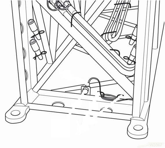
There is a cable with a plug (3) at the rear of the 16ft sections (Figure4-84).
For transport, the cable is wound around the holders (1) and the plug is inserted in the dummy socket (2).
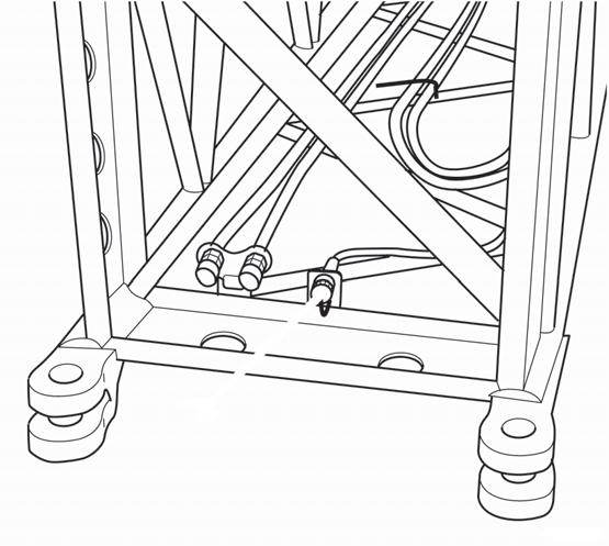
There is a plug socket (1) at the front of each 16ft (4.9m) section (Figure4-85).
For transport, the sockets are covered with protective caps.
At the 72ft (22.0m) Boom Extension
Establishing a Connection
• Connect the cable of the 33ft (10.1m) section to the socket of the second 16ft (4.9m) section at the front.
• Connect the cable of the 16ft (4.9m) section to the socket at the main boom.
Disconnecting
• Detach the electrical connection between 33ft (10.1m) and 16ft (4.9m) section.
• Detach the electrical connection between 16ft (4.9m) section and main boom head.
• Prepare the electrical connections at the 33ft (10.1m) section for transport.
At the 89ft (27.1m) Boom Extension
Establishing a Connection
• Connect the cable of the 33ft (10.1m) section to the socket of the second 16 ft (4.9 m) section at the front.
• Connect the cable of the second 16ft (4.9m) section to the socket of the first 16ft (4.9m) section at the front.
• Connect the cable of the first 16ft (4.9m) section to the socket at the main boom head.
Disconnecting
• Detach the electrical connection between the 33ft (10.1m) and front 16ft (4.9m) section.
• Detach the electrical connection between the two 16ft (4.9m) sections.
• Detach the electrical connection between the rear 16ft (4.9m) section and the main boom head.
• Prepare the electrical connections at the 16ft (4.9m) section for transport.
• Prepare the electrical connections at the 33ft (10.1m) section for transport.
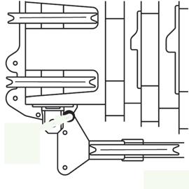
Unfolding/Folding the Deflection Sheave on the 16ft (4.9m) Section
This section describes only the unfolding and folding of the deflection sheave on the 16ft (4.9m) section.
For work with the boom extension, you must fold out the deflection sheaves on the rear 16ft (4.9m) section.
Fold the deflection sheave for transport.
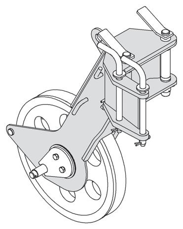
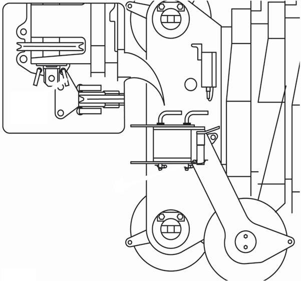
Folding Out Deflection Sheave
• Fold the deflection sheave down as far as possible.
• Insert the pin in the bore hole (3) and secure it with a retaining needle.
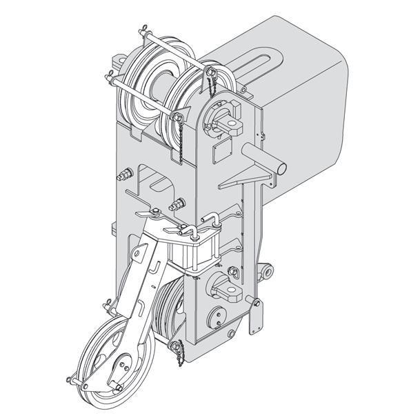
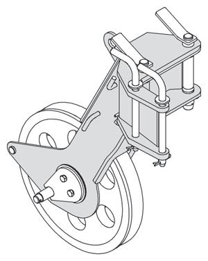
Positioning/Removing the Hoist Cable
Danger
Risk of accidents due to falling parts. Always secure the hoist cable holding rollers and rods with retaining pins. This prevents elements from becoming loose, falling down and injuring people.
Positioning Hoist Cable
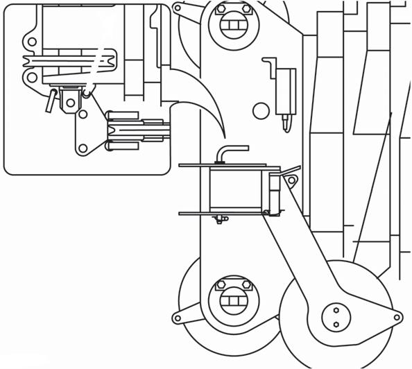
• Remove the hoist rope holding rollers and rods (1) (Figure4-88).
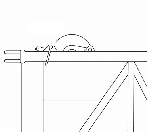
• Pull the pin (2) out of the bore (3) (Figure4-86).
• Fold the deflection sheave on the strut (1) upwards until the locking positions are aligned with the bore hole (3).
• Fasten the deflection sheave for transport.
Folding In Deflection Sheave
• Guide the hoist rope via the deflection sheaves (3) and via the head sheave (2) on the 33ft (10.1m) section or on the 23ft (7m) section. Put all hoist cable holding rollers and rod back in place and secure these with retaining pins.
• Attach the overhaul ball.
• Install the A2B weight assembly.
Removing Hoist Cable
Danger
Risk of accidents due to falling parts. Always secure the hoist cable holding rollers and rods with retaining pins. This prevents elements from becoming loose, falling down and injuring people.
• Unpin the overhaul ball.
• Remove the hoist rope holding rollers and rods (1) (Figure4-88).
• Take the hoist cable off the head sheave (2) and the deflection sheaves (3) and place it onto the ground on the left side.
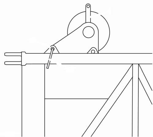
• Hold the deflection sheave by the strut (1) and remove the pin (2) from the bore (3) (Figure4-87).
• Put all hoist cable holding rollers and rods back in place and secure them with retaining pins.
Traveling with Hydraulic Luffing or Manually Offsettable Boom Extension and/or Inserts Erected
Refer to sub-section titled Battery Disconnect, page 3-26 for traveling with extension and /or inserts erected.
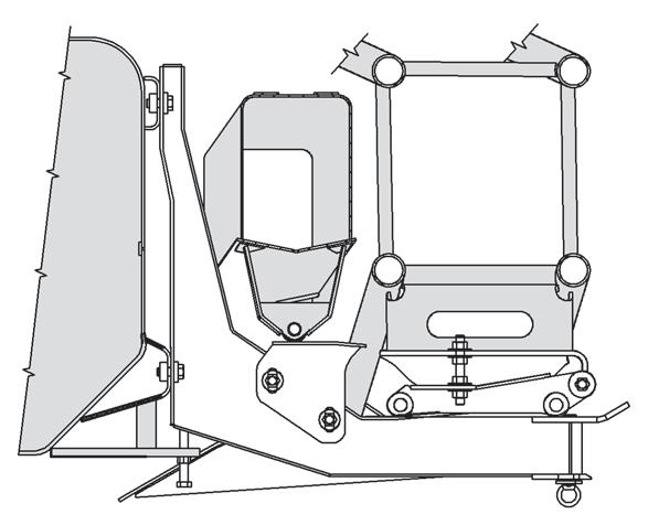
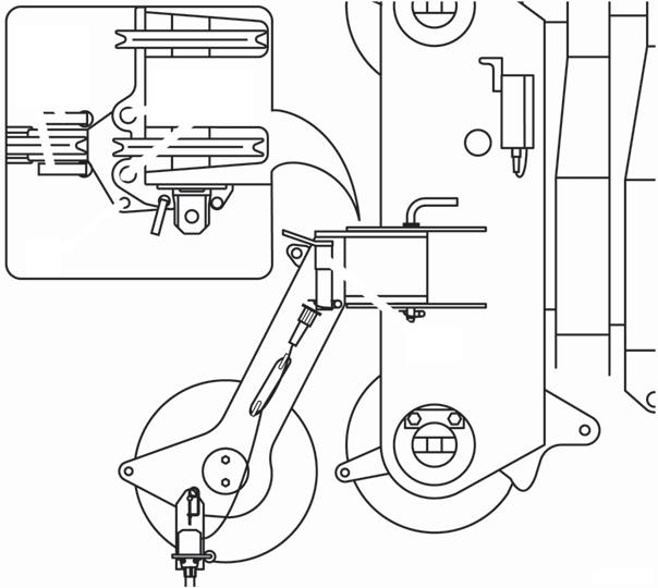
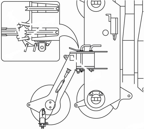
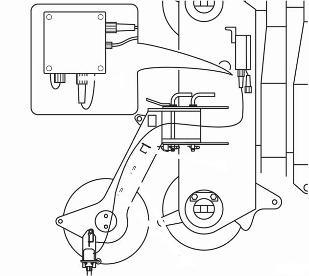
Adjustment Procedure for Stowage Brackets for Hydraulic Luffing Jib
1. Loosen items 1 and 2 that secures item 3 (Figure4-89).
2. Loosen item 4 that secures item 5.
3. Adjust item 5 so as to move item 3 to its highest position on the boom.
NOTE: Caution must be taken during this adjustment so as not to bind up other brackets. This is required to assure that the boom extension nose will clear the valve cover on the side of the turntable.
4. Tighten items 1 and 2 that secures item 3 (Figure4-89).
5. Tighten item 4 that secures item 5.
6. Using the luffing jib offset cylinder, adjust the boom extension adapter so that the pin holes align with the pin holes in the boom nose.
7. Adjust the other boom extension hanger brackets so as to get proper support and alignment for easy pin installation at the boom nose.
AUXILIARY SINGLE-SHEAVE BOOM NOSE (ADDITIONAL EQUIPMENT)
Identification
The auxiliary single-sheave boom nose is designed for the crane it was delivered with.
Caution
Operate the crane only with the auxiliary single-sheave boom nose that has the identical serial number.
If you wish to use the auxiliary single-sheave boom nose on several Manitowoc cranes, it needs to be adapted to the corresponding crane and marked with all the serial numbers.
Caution
The auxiliary single-sheave boom nose should only be adjusted by Manitowoc Crane Care at the particular location.
• Secure the auxiliary single-sheave boom nose to the holding device using a pin (1).
• Secure the pin (1) with a retaining pin (4).
• Depending on the application, bring the auxiliary singlesheave boom nose into transport position or working position.
The serial number (1) is on a plate, in the front on the auxiliary single-sheave boom nose (Figure4-90).
Installing/Removing Auxiliary Single-Sheave Boom Nose
Danger
Risk of accidents if boom nose should fall off! During installation and removal, always use the proper materials with sufficient load bearing capacities.
Installing Auxiliary Single-Sheave Boom Nose
• Loosen the retaining pin (4) and remove the pins (1) from the bearing point (2) (Figure4-91).
• Use an auxiliary crane to couple the holding device to the connection eyes (3) on the auxiliary boom nose and lift it to the left onto the main boom head.
• Align the auxiliary single-sheave boom nose so that the bearing point (2) lines up to the front bore holes in the holding device.
Removing the Auxiliary Single-Sheave Boom Nose
• Attach an auxiliary crane to the connection eyes of the boom nose.
In the working position, the auxiliary single-sheave boom nose is positioned in front of the main boom head and is fastened with three pins (1) (Figure4-92).
• Remove the retaining pins and draw all the pins out of the bores and bearing points.
In the transport position, the auxiliary single-sheave boom nose is positioned to the side of the main boom head and is fastened with two pins.
RIGGING THE AUXILIARY SINGLE-SHEAVE BOOM NOSE
Rigging in Transport Position
• Remove the retaining pins and draw all the pins out of the bores and bearing points.
• In the transport position, the auxiliary single-sheave boom nose is positioned to the side of the main boom head and is fastened with two pins.
• Lift the auxiliary single-sheave boom nose from the head of the main boom.
• Insert the two thin pins (1) and (3) into the bearing points (2) and (4) on the auxiliary single-sheave boom nose (Figure4-93).
• Insert the two pins (5) into the mounting brackets (6) in front on the auxiliary single-sheave boom nose.
• Secure all pins using retainer pins.
On the left side of the main boom head there is a holding device. In transport position, the boom nose is connected to the rear bore holes on the holding device (Figure4-94).
• Remove the retaining pins and take both pins (1) out of the bearing points (2) at the front of the main boom head (Figure4-95).
• Insert both pins into the holders (3) and secure them with retaining pins.
• Release the retaining pin and remove the thin pin from the bearing point (4).
• Slew the auxiliary boom nose to the side of the main boom head.
• Using the thin pin (1), fasten the auxiliary single-sheave boom nose to the bearing point (2) (Figure4-96).
• Secure the pin with a retaining pin.
• The auxiliary single-sheave boom nose is now in transport position.
Rigging in Working Position
• Release the retaining pin (1) and remove the thin pin from the bearing point (Figure4-98).
• Swing the auxiliary single-sheave boom nose in front of the main boom head.
On the left side of the main boom head, there is a holding device. In working position, the auxiliary single-sheave boom nose is attached to the main boom head at both bore holes (Figure4-97).
• Remove the retaining pin and take out both thick pins from the holders (Figure4-99).
• Insert both pins into the pivot points at the front of the main boom head and secure them with retaining pins.
• Insert the thin pin into the bearing point and secure it with a retaining pin.
The auxiliary single-sheave boom nose is now in working position.
Attaching and Removing Hoist Cable
• for single-reeving 16,800 lb (7.6 t)
Lifting Limit Switch In Operation
• Remove the cable holding rods from the head of the main boom and from the auxiliary single-sheave boom nose (Figure4-100).
• When reeving, guide the hoist cable over the left hand upper sheave of the main boom.
• Insert the rope holding rod into the appropriate bore holes and secure them with the corresponding retaining pins.
• Fasten the cable end clamp on the hook tackle or the hook block.
Reverse the sequence of operations to remove the hoist cable before slewing the auxiliary boom nose into transport position.
Possible Reeving Methods on the Auxiliary Single-Sheave Boom Nose
NOTE: The hoist cable may only be simply reeved (single drop).
• maximum load bearing capacity:
• Pull the plug of the connecting cable from the dummy socket (2) (Figure4-101).
• Unwind the connecting cable from the holders (3).
• Insert the plug of the connecting cable into the socket (1) on the main boom head.
• Guide the hoist cable through the lifting limit switch weight.
During Transport
• Insert the plug of the connecting cable into the dummy socket (2) (Figure4-102)
• Wind the connecting cable onto the holders (3).
• Plug the short-circuit plug into the socket (1).
Raising And Setting Down The Main Boom With Rigged Extension
NOTE: The information in this section also applies for raising and setting down the main boom with a rigged boom extension.
NOTE: To raise and lower the main boom with a rigged lattice extension, the main boom must be fully retracted.
For raising and lowering, the following prerequisites must be fulfilled:
- Apart from the hook block there is no load on the extension.
Telescoping With Rigged Extension
Warning
The main boom may become overloaded!
If you telescope the main boom with a rigged boom extension, you must not rotate the superstructure at the same time. This prevents the main boom being subjected to additional side forces and increased vibration and becoming overloaded.
NOTE: Do not actuate the slewing gear when telescoping.
Procedure If The Permissible Wind Speed Is Exceeded
Strong winds can overstrain the crane. Therefore, closely observe the instructions in table.
If the maximum permissible wind speed according to the lifting capacity table is exceeded during the main boom operation, proceed as in (Table 4-2):
Table 4-2 with wind speed up to 66 ft/s with wind speed over 66 ft/s
•Set down the load.•Set down the load.
•Slew the superstructure so that the main boom creates as little wind resistance as possible.
•Fully retract the main boom.
• Set down the lattice extension.
NOTE: The information in (Table 4-3) applies to malfunctions during operation with the 33/56ft (10.1/17.1m) lattice extension.
Table 4-3
MalfunctionCauseRemedy
No function of the lifting limit switchLifting limit switch not connectedConnect the lifting limit switch. Electrical connection between the boom head and lattice extension and between 33ft (10.1m) section and 23ft (7m) section is not established.
Lifting limit switch on the main boom head not overridden.
When operating with a 56ft (17.1m) lattice extension or boom extension, the short-circuit plug is not inserted on the head of the 33ft (12.5m) section.
Establishing electrical connection.
Override the lifting limit switch on the main boom head.
Insert short-circuit plug.
The main boom cannot be telescoped with the rigged lattice extension or boom extension.
The lattice extension can not be derricked.
The main boom is derricked to such an angle at which telescoping is not permissible
Derricking gear of the lattice extension is switched off.
Monthly Maintenance Work
Pins
Lubricate all attach, securing and retaining pins.
- the pins for the pin connection on the lattice extension,
- the retaining pins on the return pulleys,
- the retaining pins used for fastening the lattice extension sections for transport,
- the spring latch on the run-up rail.
NOTE: The maintenance interval applies to average operation. Also, lubricate the pins after highpressure cleaning and generally at an interval that will prevent them getting dry.
Lubricating Joint on 33ft (10.1m) Section
Derrick the main boom to the required angle.
Switch on the derricking gear of the lattice extension.
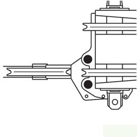
The joints are lubricated via lubricating nipples. On either side of 33ft (10.1m) section, there is a lubricating nipple (1) at the pivot point (Figure4-103).
• Clean the lubricating nipple and lubricate it with a grease gun.
• Also lubricate the joint on the other side. Lubricate the derricking cylinder in 33ft (10.1m) section
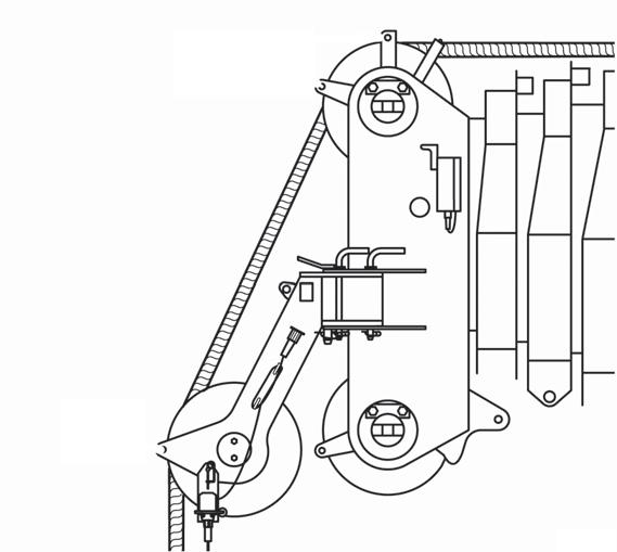
The derricking cylinder is lubricated via a lubricating nipple. On head and foot axle there is one lubricating nipple each (1) (Figure4-104).
• Clean the lubricating nipples and insert grease into the lubricating nipple with a grease gun.
Section 5 Lubrication
General
Following the designated lubrication procedures is important in ensuring maximum crane lifetime and utilization. The procedures and lubrication charts in this section include information on the types of lubricants used, the location of the lubrication points, the frequency of lubrication, and other information.
Environmental Protection
Dispose of waste properly! Improperly disposing of waste can threaten the environment.
Potentially harmful waste used in Manitowoc cranes includes — but is not limited to — oil, fuel, grease, coolant, air conditioning refrigerant, filters, batteries, and cloths which have come into contact with these environmentally harmful substances.
Handle and dispose of waste according to local, state, and federal environmental regulations.
When filling and draining crane components, observe the following:
• Do not pour waste fluids onto the ground, down any drain, or into any source of water.
• Always drain waste fluids into leak proof containers that are clearly marked with what they contain.
• Always fill or add fluids with a funnel or a filling pump.
• Immediately clean up any spills.
Lubricants And Lubrication Intervals
The service intervals specified are for normal operation where moderate ambient temperature, humidity, and atmospheric conditions prevail. In areas of extreme conditions, the service periods and lubrication specifications should be altered to meet existing conditions.For information on extreme condition lubrication, contact your local Manitowoc Cranes distributor or Manitowoc Crane Care.
Lube intervals are to be used as a guideline only. Actual lube intervals should be formulated by the operator to correspond according to conditions such as continuous duty cycles and/ or hazardous environments.
NOTE: All fluids and lubricants may be purchased by contacting an authorized Manitowoc distributor or Manitowoc Crane Care Parts Department.