9 minute read
RT800E


Transportation on a Separate Vehicle
Danger
Risk of accidents from a falling lattice extension. Only attach the lattice extension in such a way that it is positioned in the center of gravity and always use lifting gear with sufficient lifting capacity. This prevents the lattice extension from fallin g and injuring people while loading.
• Check if all the required connections for transport condition are established.
• For transportation, place the lattice extension on the skid at the front and onto the lower cross strut at the rear of the 33 ft (10.1 m) section.
• Always secure the lattice extension on the separate vehicle with belts to prevent slipping and overturning.
Caution
Risk of damaging the lattice extension. Always secure the lattice extension by tying it down with suitable belts when it is transported on the separate vehicle. This prevents the two-stage swingaway lattice extension tipping and becoming damaged during transportation.
Connecting and Disconnecting the Hydraulic Boom Extension Connecting
Warning
If the hose couplings are detached from the boom after the hose drum lock pin has been released, do not release the hose couplings until they have been attached to the boom. If the hose couplings are released after being detached from the boom, the hoses will spring back uncontrollably due to the spring force in the hose drum.
When working with the main boom for longer periods of time, the hydraulic connection between the hose drum and the main boom should be disconnected. This prevents unnecessary reeling and unreeling of the hose (Figure4-72)
Establish a Hydraulic Connection Between the Lattice Extension and the Main Boom
If the hoses are stowed on the holder on the boom base section, release the hose drum lock pin and pull the hydraulic hoses toward the boom nose. Anchor the hydraulic couplings at the holder on the boom nose. Guide the hydraulic hoses through the guide rollers.
1. Unwind the hoses on the lattice extension.
2. Remove the dust caps from the couplings on the lattice extension and the drum hoses.
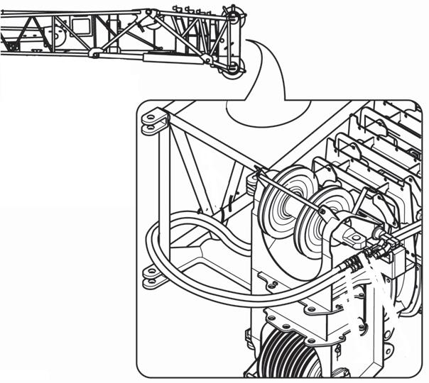
3. Connect the hose drum hoses to the hoses on the lattice extension. Do not detach the drum hoses from the holder on the boom nose (Figure4-70).
Item
1Quick Couplings
2Hose Line
3Holders
Disconnect the
Description
Extension and the Main Boom.
Warning
If the hose couplings are detached from the boom after the hose drum lock pin has been released, do not release the hose couplings until they have been attached to the boom. If the hose couplings are released after being detached from the boom, the hoses will spring back uncontrollably due to the spring force in the hose drum.
1. Disconnect the hoses from the lattice extension from the drum hoses. Do not detach the drum hoses from the boom nose (Figure4-71).
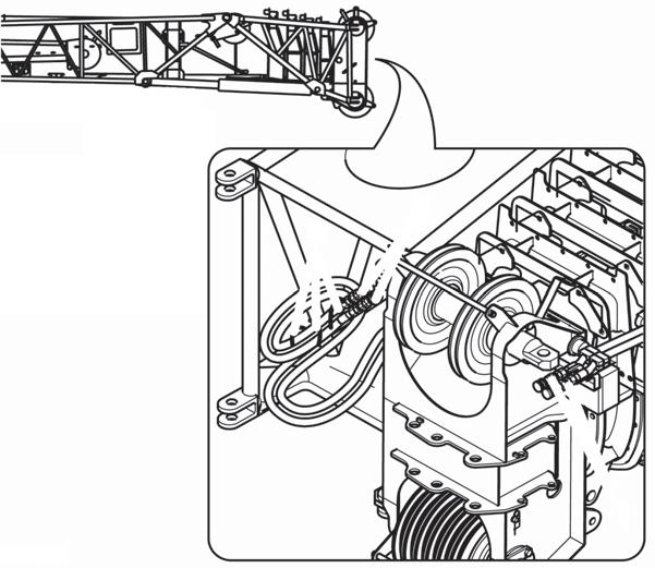
NOTE: When working with the main boom for longer periods of time, the connection between the hose drum and the boom nose should be disconnected. This prevents unnecessary reeling and unreeling of the hose.
2. Remove the hoses from the boom nose. Retract the hydraulic hoses to the holder on the boom base section.
3. Engage the hose drum lock pin into hole on the drum.
4. Wind the hoses onto the boom extension for storage.
5. Install dust caps attached to all couplings on the lattice extension and the drum hoses.
Establish an Electrical Connection Between the Lattice Extension and the Main Boom
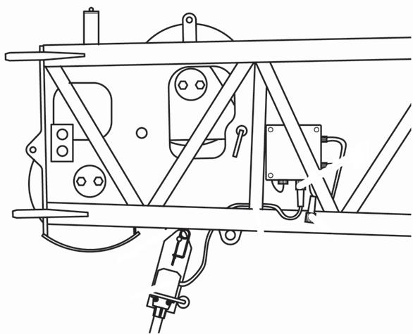
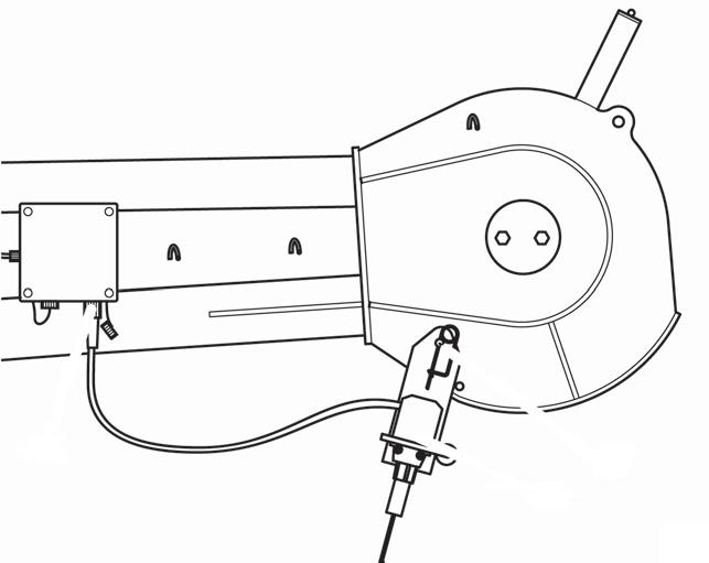
1. Remove the 17 pin bypass plug from the electrical junction box on the boom nose (Figure4-72).
2. Unwind the electrical cable from the lattice extension.
3. Disconnect the cable from the dummy plug on the boom extension adapter.
4. Connect the boom extension cable to the boom nose junction box.
Establish an Electrical Connection Between the Lattice Extension and Anti-Two Block Switch
NOTE: The anti-two block switch supplied with the boom extension is used for operation of the 33ft (10.1m) and 56ft (17m) sections. The junction box connection for the section that is not in use must be overridden with a bypass plug.
1. Install the anti-two block switch on the appropriate pin near the nose sheave of the section being used. Secure the switch to the boom extension with a retaining pin.
2. Remove the bypass plug and connect the wire for the anti-two block switch to the junction box located near the nose sheave.
Disconnect the Electrical Connection Between the Lattice Extension and the Main Boom.
1. Disconnect the boom extension cable from the boom nose junction box.
2. Wind the cable onto the boom extension for storage.
3. Connect the cable to the dummy plug on the boom extension adapter.
4. Install the 17 pin bypass plug into the open connector on the boom nose junction box.
Hydraulic Connection at the Boom Extension
The hydraulic supply is required for raising and lowering the lattice extension. You must re-establish the hydraulic connection of the hose drum if it has been detached in order to work with the main boom.
Transport Condition of the Connections
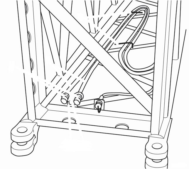
For transport, bring the hydraulic connections always into the following condition (Figure4-73).
The hydraulic hoses (5) are in the 16ft (4.9m) section with deflection sheave. For transport, the hydraulic hoses are clamped in the holders (3).
At the two front hose ends, there are two quick-action couplings (4) that are attached to a plate (1). For transport, the plate is attached in the holder (2) at the front.
The quick-action couplings (4) are at the rear hose ends (3). For transport, the hydraulic hoses are clamped in the holders (2).
At the 72ft (22.0m) Boom Extension
All connections are made via quick-action couplings. Half couplings which belong together are color coded.
Establishing a Connection
• Connect the rear hose ends (1) of the 16ft (4.9m) section to the quick-action couplings (2) at the main boom head.
• Connect the hydraulic hoses (3) of the 33ft (10.1m) section to the quick-action couplings (4) of the 16ft (4.9m) section at the front.
Disconnecting
• Disconnect all the quick-action couplings and cover them with protective caps.
• Make the connections ready for transport.
At the 89ft (27m) Boom Extension
All connections are made via quick-action couplings. Half couplings which belong together are color coded.
Establishing a Connection
• Connect rear hose ends of the 16ft section to the quickaction couplings (2) at the main boom head.
• Detach the hydraulic hose from the holders in the 16ft (4.9m) section with deflection sheave.
• Remove the plate from the holder 16ft (4.9m) section.
• Attach the plate in the holder and clamp the hydraulic hoses into the holders in the front 16ft (4.9m) section.
• Connect the hydraulic hoses of the 33ft (10.1m) section to the quick-action couplings of the 16ft (4.9m) section at the front.
Disconnecting
• Disconnect all the quick-action couplings and cover them with protective caps.
• Make the connections of the 16ft (4.9m) sections ready for transport.
Clamp the connections of the 33ft (10.1m) section to the holders at the 33ft (10.1m) section.
Lifting Limit Switch on the Lattice Extension
The functions raise hoist, extend main boom and lower main boom are monitored during operation with the lattice extension by the lifting switch on the lattice extension and are switched off when the lifting limit switch is actuated.
NOTE: The same lifting limit switch is used for lattice extension and main boom.
Overriding Connection on Main Boom
For operation with the lattice extension you must remove the lifting limit switch on the main boom and override the connection.
• Insert the short-circuit plug (1) in the socket for the connection of the lifting limit switch (Figure4-74).
On 33ft (10.1m) swingaway lattice extension (Figure4-74)
• Attach the lifting limit switch (3) in the holder (4) and secure it with a retaining pin.
• Remove the short-circuit plug (2) from the socket (1).
• Connect the lifting limit switch on the socket (1).
• When unrigging you must insert the short-circuit plug (2) back in the socket (1).
On the 56ft (17.1m) Two-Stage Swingaway Lattice
Extension
NOTE: For operation with the 56ft (17.1m) two-stage swingaway lattice extension the connection for the lifting limit switch on the 33ft (10.1m) section must be overridden with a short-circuit plug.
• Attach the lifting limit switch (2) on the shackle (1) and secure it with a retaining pin (Figure4-75).
• Connect the lifting limit switch on the socket (3).
• When stowing, close the socket (3) with the protective cap.
Folding Out/In the Deflection Sheaves on the 33ft (10.1m) Section
To prevent the hoist rope dragging on the main boom or lattice extension during operation with the lattice extension or boom extension, the hoist rope is guided via deflection sheaves.
On the 33ft (10.1m) section, there is a deflection sheave at the rear (1) (Figure4-76). Fold out the deflection sheave for operation w/the 33ft or 56ft swingaway at 20° or 40° offsets.
NOTE: For zero (0°) offset, leave the mast in the stowed position as shown in Figure 4-77.
The sheave must be folded out:
• for operation with the swingaway lattice extension,
• for operation with the 56ft (17.1m) two-stage swingaway lattice extension.
For transportation the mast sheave must be folded in.
Folding Rear Deflection Sheave
Positioning/Remove the Hoist Cable
Caution
Always hold the deflection sheave by the handle, when removing the pin. You might get your fingers crushed if you hold the sheave by the side plates.
Folding Out Deflection Sheave
• Remove the pin (2) from the storage lug (1) (Figure4-78).
• Fold the deflection sheave up and secure it with the pin in the lug (3).
• Secure the pin with a retaining pin.
Folding In Deflection Sheave
• Remove the pin (2) from the lug (3).
• Fold the deflection sheave down and insert the pin in the storage lug (1).
• Secure the pin with a retaining clip.
Danger
Risk of accidents due to falling parts.
Always secure the hoist cable holding rollers and rods with retaining pin. This prevents elements from coming loose, falling down and injuring people.
Positioning Hoist Cable
• Remove the hoist cable holding rollers and rod (1) (Figure4-77).
• Guide the hoist rope via the deflection sheaves (3), if used and via the head sheave (2) on the 33ft (10.1m) section or on the 23ft (7m) section. Put all hoist cable holding rollers and rods back in place and secure these with retaining pins.
• Attach the overhaul ball.
• Install the A2B weight assembly.
Removing Hoist Cable
• Unpin the overhaul ball.
• Remove the hoist cable holding rollers and rods (1).
• Take the hoist cable off the head sheave (2) and the deflection sheaves (3), if used, and place it onto the ground on the left side.
Setting the Folding Swingaway Extension Offset
Refer to Figure 4-79.
Danger
Ensure any blocking material used is adequate to support the weight of the extension assembly without tipping or falling.
1. Extend and set the outriggers and swing the boom to over the front. Position the boom to above horizontal.
2. Block up under the tip of the extension assembly section.
To obtain maximum degree offset, remove pin and
3. To set the offset from a lesser degree to higher degree, perform the following procedures.
Caution
Do not overload the extension anchor fittings or the extension base section when lowering the boom.
a. Slowly lower the boom until the pressure is relieved on the offset link pins.
NOTE: For 20° or 40° offset, make sure the mast is in the raised position.
b. Remove the offset link clip pins and attach pins securing the offset links in the lesser degree offset position. If going to maximum offset, stow them in the stowage lugs. If going to the intermediate (20°) offset, install them in the offset links for that degree of offset.
c. Slowly elevate and telescope the boom at the same time so that the extension does not move off of the blocking until the offset links take the full weight of the extension.
d. Reeve the hoist cable as described under normal erecting procedures.
REMOVING THE BI-FOLD MANUAL BOOM EXTENSION
Danger
To prevent serious injury or death, always wear personal protective equipment; i.e., a hard hat, eye protection, gloves and metatarsal boots.
1. Before removing the boom extension make sure the crane is set up on outriggers using normal setup procedures. Refer to Setting the Outriggers, page 3-35
NOTE: An auxiliary crane with sling is required to remove the bi-fold boom extension.
1. Retract the main boom completely and lower it into the horizontal position.
2. Unreeve the hoist cable from the hook block and remove it from the boom extension.
3. Fold in the deflection sheave on the 33ft (10.1m) section.
NOTE: If crane is equipped with a hydraulic luffing boom extension, disconnect the hydraulic couplings at boom nose. Stow hoses on boom extension. Refer to Connecting and Disconnecting the Hydraulic Boom Extension in this section.
4. Disconnect electrical connection between the lattice extension and the main boom.
5. Attach auxiliary crane sling to bi-fold swingaway extension.
Warning
Lattice extension must be supported by an auxiliary crane before removing pins.
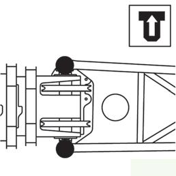
6. Remove locking pins (Figure4-80) on both sides between 33ft (10.1m) section and main boom head and remove the bi-fold swingaway extension.
7. Check the transport condition of the bifold swingaway extension.
INSTALLING/REMOVING 16FT (4.9M) SECTIONS
- In order to rig the 72ft (22m) boom extension, you must install the 16ft (4.9m) section with support roller in front of the main boom head.
- In order to rig the 89ft (27.1m) boom extension, you must additionally install the 16ft (4.9m) section without support roller in front of the 16ft (4.9m) section with support roller.
NOTE: An auxiliary crane must be used to install and remove the 16ft (4.9m) sections.